Patent application title: PRESSURE-RELIEF MECHANISM TO IMPROVE SAFETY IN LITHIUM-POLYMER BATTERY CELLS
Inventors:
Ramesh C. Bhardwaj (Fremont, CA, US)
Apple Inc. (Cupertino, CA, US)
Ramesh C. Bhardwaj (Fremont, CA, US)
Taisup Hwang (Santa Clara, CA, US)
Taisup Hwang (Santa Clara, CA, US)
Richard M. Mank (Cupertino, CA, US)
Richard M. Mank (Cupertino, CA, US)
Assignees:
Apple Inc.
IPC8 Class: AH01M212FI
USPC Class:
429 82
Class name: Chemistry: electrical current producing apparatus, product, and process having specified venting, feeding or circulation structure (other than feeding or filling for activating deferred action-type battery) venting structure
Publication date: 2013-05-09
Patent application number: 20130115491
Abstract:
The disclosed embodiments relate to a battery cell which includes a
weakness for relieving pressure. This battery cell includes a jelly roll
comprising layers which are wound together, including a cathode with an
active coating, a separator and an anode with an active coating. The
jelly roll also includes a first conductive tab coupled to the cathode
and a second conductive tab coupled to the anode. The jelly roll is
enclosed in a flexible pouch, wherein the first and second conductive
tabs extend through seals in the pouch to provide terminals for the
battery cell. This pouch includes a weakness which yields when internal
pressure in the pouch exceeds a threshold to create a hole which releases
the internal pressure.Claims:
1. A battery cell with a weakness for relieving pressure, comprising: a
jelly roll comprising layers which are wound together, including a
cathode with an active coating, a separator, and an anode with an active
coating; a pouch, which encloses the jelly roll, wherein the pouch is
flexible; a first conductive tab coupled to the cathode; and a second
conductive tab coupled to the anode; wherein the first and second
conductive tabs extend through seals in the pouch to provide terminals
for the battery cell; and wherein the pouch includes a weakness which
yields when internal pressure in the pouch exceeds a threshold to create
a hole which releases the internal pressure.
2. The battery cell of claim 1, wherein the pouch includes multiple weaknesses at different locations on the pouch.
3. The battery cell of claim 1, wherein the weakness includes one of: a corner of the pouch which is cut; a pattern of tiny holes formed in a seal for the pouch; and a thinned region of the pouch material.
4. The battery cell of claim 1, wherein the weakness is located on one of: a side seal for the pouch; a terrace seal for the pouch; a corner of the pouch; a fold in the pouch material; and a location on a surface of the pouch which is not part of a seal.
5. The battery cell of claim 1, wherein the pouch is comprised of: a layer of aluminum; and a layer of polypropylene.
6. The battery cell of claim 1, wherein the battery cell is one of: a lithium-polymer battery cell; and a silver-zinc battery cell.
7. A battery pack comprising one or more battery cells coupled together and enclosed in a hard case, wherein each of the one or more battery cells includes: a jelly roll comprising layers which are wound together, including a cathode with an active coating, a separator, and an anode with an active coating; a pouch, which encloses the jelly roll, wherein the pouch is flexible; a first conductive tab coupled to the cathode; and a second conductive tab coupled to the anode; wherein the first and second conductive tabs extend through seals in the pouch to provide terminals for the battery cell; and wherein the pouch includes a weakness which yields when internal pressure in the pouch exceeds a threshold to create a hole which releases the internal pressure.
8. The battery pack of claim 7, wherein the one or more battery cells are coupled together: in series; in parallel; or in series and parallel.
9. The battery pack of claim 7, wherein each pouch includes multiple weaknesses at different locations on the pouch.
10. The battery pack of claim 7, wherein the weakness includes one of: a corner of the pouch which is cut; a pattern of tiny holes formed in a seal for the pouch; and a thinned region of the pouch material.
11. The battery pack of claim 7, wherein the weakness is located on one of: a side seal for the pouch; a terrace seal for the pouch; a corner of the pouch; a fold in the pouch material; and a location on a surface of the pouch which is not part of a seal.
12. The battery pack of claim 7, wherein the pouch is comprised of: a layer of aluminum; and a layer of polypropylene,
13. The battery pack of claim 7, wherein each battery cell is one of: a lithium-polymer battery cell; and a silver-zinc battery cell.
14. A portable computing device, comprising: a processor; a memory; and a battery pack, which includes one or more battery cells coupled together; wherein each of the one or more battery cells includes: a jelly roll comprising layers which are wound together, including a cathode with an active coating, a separator, and an anode with an active coating; a pouch, which encloses the jelly roll, wherein the pouch is flexible; a first conductive tab coupled to the cathode; and a second conductive tab coupled to the anode; wherein the first and second conductive tabs extend through seals in the pouch to provide terminals for the battery cell; and wherein the pouch includes a weakness which yields when internal pressure in the pouch exceeds a threshold to create a hole which releases the internal pressure.
15. The portable computing device of claim 14, wherein the portable device includes one of: a laptop or notebook computer system; a personal digital assistant; and a cellular telephone.
16. A method for assembling a battery cell, comprising: obtaining a jelly roll comprising layers which are wound together, including a cathode with an active coating, a separator, and an anode with an active coating, wherein the jelly roll includes a first conductive tab coupled to the cathode and a second conductive tab coupled to the anode; obtaining a pouch to accommodate the jelly roll, wherein the pouch is flexible; and sealing the jelly roll in the pouch, wherein the pouch is sealed so that the first and second conductive tabs extend through seals in the pouch to provide terminals for the battery cell; wherein the pouch includes or is configured to include one or more weaknesses, which yield when internal pressure in the pouch exceeds a threshold to create a hole which releases the internal pressure.
17. The method of claim 16, wherein the weakness in the pouch is created: prior to sealing the jelly roll in the pouch; or after sealing the jelly roll in the pouch.
18. The method of claim 16, wherein creating the weakness in the pouch involves creating multiple weaknesses at different locations on the pouch.
19. The method of claim 16, wherein the weakness includes one of: a corner of the pouch which is cut; a pattern of tiny holes formed in a seal for the pouch; and a thinned region of the pouch material.
20. The method of claim 16, wherein the weakness is located on one of: a side seal for the pouch; a terrace seal for the pouch; a corner of the pouch; a fold in the pouch material; and a location on a surface of the pouch which is not part of a seal.
21. The method of claim 16, wherein the pouch is comprised of: a layer of aluminum; and a layer of polypropylene,
22. The method of claim 16, wherein the battery cell is one of: a lithium-polymer battery cell; and a silver-zinc battery cell.
Description:
RELATED CASES
[0001] The instant application is a divisional of, and hereby claims priority under 35 U.S.C. §120 to, pending U.S. patent application Ser. No. 12/622,788, which is titled "Pressure-Relief Mechanism to Improve Safety in Lithium-Polymer Battery Cells," by Ramesh C. Bhardwaj, Taisup Hwang and Richard M. Mank, which was filed on 20 Nov. 2009, and which is herein incorporated by reference.
BACKGROUND
[0002] 1. Field
[0003] The disclosed embodiments relate to techniques for improving safety in rechargeable lithium-polymer battery cells. More specifically, the disclosed embodiments relate to the design of a pressure-relief mechanism which improves the safety in lithium-polymer battery cells.
[0004] 2. Related Art
[0005] Rechargeable batteries are presently used to provide power to a wide variety of portable electronic devices, including laptop computers, cell phones, PDAs, digital music players and cordless power tools. The most commonly used type of rechargeable battery is a lithium battery, which can include a lithium-ion or a lithium-polymer battery.
[0006] A potential safety issue can arise if there is a gas buildup within a rechargeable lithium battery cell. This can occur, for example, if the cell is overcharged, if there is a short within the cell, or if the cell is left uncharged for a significant period of time. This type of gas buildup can potentially cause the battery cell to swell or even to explode, which can seriously damage the portable electronic device, and may even start a fire.
[0007] To alleviate this problem, cylindrical lithium-ion battery cells are often equipped with a vent valve to release the internal pressure in the battery cell when a gas buildup occurs. However, there exist no comparable pressure-relief mechanisms for lithium-polymer batteries, which are becoming increasingly popular in portable electronic devices. A lithium-polymer battery is typically enclosed in a flexible pouch, which is lightweight and inexpensive to manufacture. However, no pressure-relief mechanism has been developed for these pouches so far.
SUMMARY
[0008] The disclosed embodiments relate to a battery cell which includes a weakness for relieving pressure. This battery cell includes a jelly roll comprising layers which are wound together, including a cathode with an active coating, a separator, and an anode with an active coating. The jelly roll also includes a first conductive tab coupled to the cathode and a second conductive tab coupled to the anode. The jelly roll is enclosed in a flexible pouch, wherein the first and second conductive tabs extend through seals in the pouch to provide terminals for the battery cell. This pouch includes a weakness which yields when internal pressure in the pouch exceeds a threshold to create a hole which releases the internal pressure.
[0009] In some embodiments, the pouch includes multiple weaknesses at different locations on the pouch.
[0010] In some embodiments, the weakness can include: a V-shaped notch cut into a seal for the pouch; a half-circle cut into a seal for the pouch; a pattern of tiny holes formed in a seal for the pouch; and a thinned region of the pouch material.
[0011] In some embodiments, the weakness can be located on: a side seal for the pouch; a terrace seal for the pouch; a corner of the pouch; a fold in the pouch material; and a location on a surface of the pouch which is not part of a seal.
[0012] In some embodiments, the pouch is comprised of a layer of aluminum and a layer of polypropylene.
[0013] In some embodiments, the battery cell is a lithium-polymer battery cell, or a silver-zinc battery cell.
BRIEF DESCRIPTION OF THE FIGURES
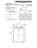
[0014] FIG. 1 illustrates a battery cell in accordance with the disclosed embodiments.
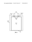
[0015] FIG. 2 illustrates a battery cell with V-shaped notches cut into seals for a pouch in accordance with the disclosed embodiments.
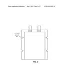
[0016] FIG. 3 illustrates a battery cell with half-circles cut into seals for a pouch in accordance with the disclosed embodiments.
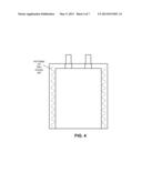
[0017] FIG. 4 illustrates a battery cell with patterns of tiny holes formed in a seal for a pouch in accordance with the disclosed embodiments.
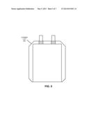
[0018] FIG. 5 illustrates a battery cell including a pouch with corner cuts in accordance with the disclosed embodiments.
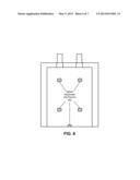
[0019] FIG. 6 illustrates a battery cell with weak regions formed in the pouch material in accordance with the disclosed embodiments.
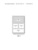
[0020] FIG. 7 illustrates a portable computing device in accordance with the disclosed embodiments.
DETAILED DESCRIPTION
[0021] The following description is presented to enable any person skilled in the art to make and use the disclosed embodiments, and is provided in the context of a particular application and its requirements. Various modifications to the disclosed embodiments will be readily apparent to those skilled in the art, and the general principles defined herein may be applied to other embodiments and applications without departing from the spirit and scope of the disclosed embodiments. Thus, the disclosed embodiments are not limited to the embodiments shown, but are to be accorded the widest scope consistent with the principles and features disclosed herein.
[0022] The data structures and code described in this detailed description are typically stored on a computer-readable storage medium, which may be any device or medium that can store code and/or data for use by a computer system. The computer-readable storage medium includes, but is not limited to, volatile memory, non-volatile memory, magnetic and optical storage devices such as disk drives, magnetic tape, CDs (compact discs), DVDs (digital versatile discs or digital video discs), or other media capable of storing code and/or data now known or later developed.
[0023] The methods and processes described in the detailed description section can be embodied as code and/or data, which can be stored in a computer-readable storage medium as described above. When a computer system reads and executes the code and/or data stored on the computer-readable storage medium, the computer system performs the methods and processes embodied as data structures and code and stored within the computer-readable storage medium. Furthermore, the methods and processes described below can be included in hardware modules. For example, the hardware modules can include, but are not limited to, application-specific integrated circuit (ASIC) chips, field-programmable gate arrays (FPGAs), and other programmable-logic devices now known or later developed. When the hardware modules are activated, the hardware modules perform the methods and processes included within the hardware modules.
Battery Cell
[0024] FIG. 1 illustrates a battery cell 100 in accordance with the disclosed embodiments. Battery cell 100 includes a jelly roll 101 comprising a number of layers which are wound together, including a cathode with an active coating, a separator, and an anode with an active coating. Jelly rolls are well known in the art and will not be described further. During assembly of battery cell 100, jelly roll 101 is enclosed in a flexible pouch, which is formed by folding a flexible sheet along a fold line 108. For example, the flexible sheet can be comprised of aluminum with a polymer film, such as polypropylene. After the flexible sheet is folded, the flexible sheet can be sealed, for example by applying heat along side seals 102 and along a terrace seal 104.
[0025] Note that jelly roll 101 includes conductive tabs 103 coupled to the cathode and the anode. These conductive tabs 103 extend through seals in the pouch (for example, formed using sealing tape 104) to provide terminals for battery cell 100.
[0026] Also note that a battery pack can be formed by coupling together a number of such battery cells: in series, in parallel, or both in series and in parallel. The coupled cells can then be enclosed in a hard case.
Battery Cell Including a Weakness
[0027] As mentioned above, a gas buildup can potentially occur within battery cell 100 if: battery cell 100 is overcharged; there is a short within battery cell 100; or battery cell 100 is left uncharged for a significant period of time. This gas buildup can potentially cause the battery cell to swell or even explode. To deal with this problem, the pouch includes one or more preformed weaknesses which yield when internal pressure in the pouch exceeds a threshold value to create a hole which releases the internal pressure.
[0028] There are a number of different ways to create such a weakness. For example, a number of V-shaped notches, including V-shaped notch 202, can be cut into the seals for the pouch as is illustrated in FIG. 2. These V-shaped notches can be cut using some type of cutting tool after the pouch is formed. Alternatively, a number half-circles, including half-circle 302, can be cut into the seals for the pouch as is illustrated in FIG. 3. In yet another embodiment which is illustrated in FIG. 4, instead of cutting notches in the seals, weaknesses can be created by forming a pattern of tiny holes 402 in the seals.
[0029] Weaknesses can also be formed at other locations on the battery cell pouch. For example, FIG. 5 illustrates a battery cell having a pouch with weaknesses which are formed as corner cuts 502. Alternatively, FIG. 6 illustrates a battery cell with weak regions 602 which are formed at various locations on the pouch material. These weak regions 602 can be formed, for example, by thinning the pouch material.
[0030] In general, such weaknesses can be formed at any location on the battery pouch, including at: a side seal for the pouch; a terrace seal for the pouch; a corner of the pouch; a fold in the pouch material; and any location on a surface of the pouch which is not part of a seal. Moreover, although a number of different types of weaknesses are illustrated in FIGS. 2-6, in general any type of weakness which yields to internal pressure in the battery cell can be used by the disclosed embodiments.
Computing Device
[0031] The above-described rechargeable battery cell can generally be used in any type of electronic device. For example, FIG. 7 illustrates a portable computing device 700 which includes a processor 702, a memory 704 and a display 708, which are all powered by a battery 706. Battery 706 comprises a battery pack, which includes multiple battery cells that are coupled together in series and/or in parallel.
[0032] The foregoing descriptions of embodiments have been presented for purposes of illustration and description only. They are not intended to be exhaustive or to limit the present description to the forms disclosed. Accordingly, many modifications and variations will be apparent to practitioners skilled in the art. Additionally, the above disclosure is not intended to limit the present description. The scope of the present description is defined by the appended claims.
User Contributions:
Comment about this patent or add new information about this topic:
| People who visited this patent also read: | |
| Patent application number | Title |
|---|---|
| 20190298649 | INJECTABLE IMPLANTS |
| 20190298648 | TUMESCENT DRUG DELIVERY |
| 20190298647 | COMPOSITIONS OF ANTI-NEOPLASTIC AGENTS AND METHODS OF USE |
| 20190298646 | COMPOSITIONS AND METHODS FOR TREATING INFLAMMATORY CONDITIONS |
| 20190298645 | Sand Remover for Skin and Hair |
Images included with this patent application:
 |  |
 |  |
 |  |
 |  |
| Similar patent applications: | |
| Date | Title |
|---|---|
| 2010-03-04 | Newly discovered bacterium in the family acetobacteraceae |
| 2012-11-01 | Stack-type lithium-ion polymer battery |
| 2013-03-21 | Pressure-sensitive adhesive tape for battery |
| 2013-10-03 | Polysulfone coating for high voltage lithium-ion cells |
| 2013-11-07 | Low crystallinity silicon composite anode material for lithium ion battery |
| New patent applications in this class: | |
| Date | Title |
|---|---|
| 2022-05-05 | Battery module |
| 2018-01-25 | Intumescent battery housing |
| 2018-01-25 | Battery pack |
| 2016-09-01 | Lead-acid battery |
| 2016-09-01 | Vapor pressure barriers for lead acid batteries for improved water loss performance, separators, systems, and methods of manufacture and use thereof |
| New patent applications from these inventors: | |
| Date | Title |
|---|---|
| 2022-07-21 | Composite lithium-metal anodes for enhanced energy density and reduced charging times |
| 2022-03-31 | Multiple battery configurations for space utilization |
| 2018-06-07 | Methods for determining and controlling battery expansion |
| 2016-03-31 | Efficient battery pouch |
| Top Inventors for class "Chemistry: electrical current producing apparatus, product, and process" | |
| Rank | Inventor's name |
|---|---|
| 1 | Je Young Kim |
| 2 | Norio Takami |
| 3 | Hiroki Inagaki |
| 4 | Tadahiko Kubota |
| 5 | Yo-Han Kwon |