Patent application title: LIGHTING DEVICE FOR VEHICLES
Inventors:
Hella Kgaa (Lippstadt, DE)
Niklas Stiller (Erwitte, DE)
Assignees:
HELLA KGaA
IPC8 Class: AB60Q126FI
USPC Class:
362485
Class name: Illumination supported by vehicle structure (e.g., especially adapted for vehicle) truck, trailer, or wagon
Publication date: 2013-04-11
Patent application number: 20130088883
Abstract:
The invention relates to a lighting device for vehicles, particularly for
tractors and trailers, with a housing to which light sources of differing
light generating types can be exchangeably fastened in an installed
state, wherein the light sources of differing light generating types are
assigned at least one optic element for the formation of a light module,
which is detachably connectable to a carrier frame of the housing, and
which generated a defined light function, and wherein a single lens is
placed in front of the light modules of differing light generating types
in the installed state and the carrier frame.Claims:
1. A lighting device for vehicles, particularly for tractors and
trailers, having a housing in which replaceable light sources of
differing light generating types can be fastened in an installed state,
wherein the light sources of differing light generating types are
assigned at least one optic element to form a light module being
detachably connectable with a carrier frame of the housing and generating
a defined lighting function, and wherein a single lens is placed in front
of the light modules of differing light generating types in the installed
state and the carrier frame.
2. The lighting device according to claim 1, wherein a light module of a first light generating type has a bulb light module with a reflector as an optic element, wherein in a vertex of the reflector, holding means for the fastening of the bulb to the reflector and contacting means for the contacting of the bulb to an electric lead connected to an electric energy source are arranged.
3. The lighting device according to claim 1, wherein a light module of a second light generating type has an LED light module with a number of light diodes as light source and an optic lens as optic element, the optic lens having a circumferential fastening edge for a mechanical connection with a printed circuit board, on which a number of light diodes is arranged, and that the printed circuit board has contacting means for the electric connection with the electric lead.
4. The lighting device according to claim 1, wherein a light module of a first light generating type and/or a second light generating type can be detachably fastened to the carrier frame, the carrier frame extending in a region between the lens and the light source or light sources of the light module of the first light generating type or the second light generating type.
5. The lighting device according to claim 1, wherein a light module of a first light generating type and/or a second light generating type is connected by snap-fastening to the carrier frame in the installed state, and that the carrier frame is shaped as a decorative bezel limiting the light aperture of the installed light module.
6. The lighting device according to claim 1, wherein the carrier frame has a number of openings, at whose edge a light module of a first light generating type or a second light generating type can be fastened respectively.
7. The lighting device according to claim 1, wherein the carrier frame has a friction-locked connection with the housing.
8. The lighting device according to claim 1, wherein a first opening of the carrier frame has a first light module of a first light generating type or a second light generating type for the formation of a direction indicator function and/or a second opening of the carrier frame has a light module of the first or second light generating type for the formation of a tail light and/or stop light function and/or a third opening of the carrier frame has a light module of the first or the second light generating type for the formation of a reversing light function and/or a fourth opening of the carrier frame has a light module of the first or the second light generating type for the formation of a rear fog light and/or license plate light function, wherein the first opening and the second opening and the third opening and the fourth opening of the carrier frame are covered by the same lens.
9. The lighting device according to claim 1, wherein light modules of a first light generating type and of a second light generating type have a coding marking the light defined lighting function.
10. The lighting device according to claim 1, wherein the transverse extension of a light module of a first or a second light generating type corresponds to a light active surface of the lens.
Description:
CROSS REFERENCE
[0001] This application claims priority to PCT Application No. PCT/EP2011/054891, filed Mar. 30, 2011, which in turn claims priority to German Patent Application No. 10 2010 013484.8, filed Mar. 30, 2010.
TECHNICAL FIELD OF THE INVENTION
[0002] The invention relates to a lighting device for vehicles, particularly for tractors and trailers, having a housing in which replaceable light sources of differing light generating types can be fastened in an installed state.
BACKGROUND OF THE INVENTION
[0003] From EP 1 627 772 A1, a lighting device for vehicles is known, which allows the replacement of a bulb light source by a light diode light source for the generation of the defined light function. To this end, a housing of the lighting device has a lamp holder, so that on the one hand a base of a bulb and on the other hand electrical contacting means of the LED light source can be used. The lighting device according to the prior art does therefore allow the integration of light sources of different light generating types in one housing, wherein the bulb is designed as a thermal radiation emitter and the light diode as a non-thermal radiation emitter. A disadvantage of the known lighting device is, that not only the light sources have to be replaced, but also all optic elements including a lens covering the opening of the housing.
SUMMARY OF THE INVENTION
[0004] The aim of the present invention is, therefore, the further development of a lighting device for vehicles to simplify the re-fitting of light sources of differing light generating types.
[0005] In accordance with an object of the invention, there is provided a light source of differing light generating types have assigned at least one optic element for the formation of a light module being detachably connectable with a carrier frame of the housing and generating a defined lighting function, and wherein a single lens with the same optic structure is placed in front of the light modules of differing light generating types in the installed state and the carrier frame.
[0006] According to an embodiment of the invention, light modules are formed which each comprise a light source of a defined light generating type and an optic element matched with the light source. By this means, the given light function is essentially determined by the replaceable light module itself, so that a lens arranged in the light radiating direction in front of the light module does not have to be replaced. For refitting, it is only necessary to remove the covering lens, replace the light modules and then to fasten the covering lens once again. Advantageously, a relatively simple and fast refitting is possible by this means. In addition, the reuse of the same parts, as e.g. the covering lens, the carrier frame and the housing, may result in cost savings.
[0007] According to one embodiment of the invention a first light module is executed as a bulb light module with a bulb and a reflector as optic element. A second light module is embodied as an LED light module with a number of light diodes and an optic lens. The bulb light module and the LED light module may be inserted alternatively in an opening of the carrier frame, wherein the transverse extension of the light modules preferably corresponds to the light-emitting surface of the lens. The light distribution is therefore essentially determined by the light module itself.
[0008] According to a preferred embodiment of the invention, the light modules each have contacting means for the contacting of the light source to an electric lead connected to an electric energy source. Preferably, the electric lead is executed as a cable so that the contacting may be executed in a space covered by the light module.
[0009] According to another embodiment, the carrier frame is embodied as a decorative bezel, which does not only serve for the fastening of the light module, but also defines or limits a light aperture.
[0010] According to another embodiment, the light module is connected with the carrier frame by means of snap-fastening, so that a quick and easy replacement of the light modules is made possible.
[0011] According to another embodiment, the carrier frame has several openings, each containing a light module with a different light function. Advantageously, the light modules can be fastened to the opening edged of the carrier frame according to their light function as so-called individual modules. Advantageously, a variable provision of different light functions may be achieved.
[0012] According to a development of the invention, the light modules are provided with a coding marking the light function, so that during the replacement of the light modules, a simple assignment of the respective light functions to the carrier frame openings is given.
[0013] These aspects are merely illustrative of the innumerable aspects associated with the present invention and should not be deemed as limiting in any manner. These and other aspects, features and advantages of the present invention will become apparent from the following detailed description when taken in conjunction with the referenced drawings.
BRIEF DESCRIPTION OF THE DRAWINGS
[0014] Reference is now made more particularly to the drawings, which illustrate the best presently known mode of carrying out the invention and wherein similar reference characters indicate the same parts throughout the views.
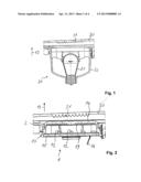
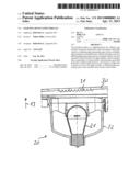
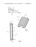
[0015] FIG. 1 A cross-section through an elongated lighting device according to FIG. 9 with a lamp chamber in which a bulb light module is integrated,
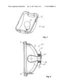
[0016] FIG. 2 A cross-section through the lamp chamber according to FIG. 1, in which the bulb light module is replaced by an LED light module,
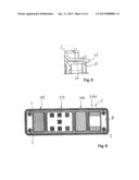
[0017] FIG. 3 A perspective front view of a bulb light module,
[0018] FIG. 4 A cross-section through the bulb light module being detachably fastened to a carrier frame,
[0019] FIG. 5 A magnified representation of a fastening section between the bulb light module and the carrier frame according to FIG. 4,
[0020] FIG. 6 A perspective front view of an LED light module,
[0021] FIG. 7 A cross-section through the LED light module fastened to the carrier frame,
[0022] FIG. 8 A magnified representation of a fastening section of the LED light module to the carrier frame according to FIG. 7 and
[0023] FIG. 9 A front view of an elongated carrier frame with a number of openings, in which LED light modules of different light functions are arranged.
DETAILED DESCRIPTION
[0024] In the following detailed description numerous specific details are set forth in order to provide a thorough understanding of the invention. However, it will be understood by those skilled in the art that the present invention may be practiced without these specific details. For example, the invention is not limited in scope to the particular type of industry application depicted in the figures. In other instances, well-known methods, procedures, and components have not been described in detail so as not to obscure the present invention.
[0025] A lighting device according to the invention for vehicles can particularly be used for tractors and trailers.
[0026] The lighting device has an elongated housing 1 being rectangular in the top view, onto which a carrier frame 2 can essentially be placed flush and which is friction-lockable for example by means of screw fastenings 3. The carrier frame 2 has 4 openings 4, 5, 6, 7 to which light modules 8, 9, 10, 11 for the generation of differing light functions can be assigned. A first opening 4 may e.g. be assigned a first light module 8 for the generation of a direction indicator function, a second opening 5 a second light module 9 for the generation of a combination tail light/stop light function, a third opening 6 a third light module 10 for the generation of a reversing light function and a fourth opening 7 a fourth light module 11 for the generation of a combination rear fog lamp/license plate lamp function. In FIG. 9, LED light modules 8, 9, 10, 11 are assigned to the openings 4, 5, 6, 7, which each have a number of LEDs 12 (light diodes) as well as an optic lens 14 arranged in front in the light radiating direction 13 as an optic element. The light diodes 12 are arranged on a common printed circuit board 15, from whose rear side protrude contacting means 16 for the connection to an electric lead, which is not represented, being connected to an electric energy source of the vehicle. In an exemplary embodiment the electric lead may be a cable, wherein the contacting means 16 also being embodied as cables are connected to the electric lead by means of plug-in contacts, which are not represented. The optic lens 14 is tub-shaped and mechanically tightly connected to the printed circuit board 15 by means of a circumferential fastening edge 17. As can be seen in FIG. 6, the optic lens 14 has a pillow optics 18 on one outside. As can be seen in FIG. 2, the optic lens 14 has a Fresnel structure 19 on the inside.
[0027] The lighting device is designed to not only receive LED light modules 8, 9, 10, 11, but also light modules of a differing light generating type. In the present embodiment, a bulb light module 20 each may alternatively be inserted in the openings 4, 5, 6, 7, having a bulb with a light generating type differing from the light diode 12. The bulb light module 20 therefore has a bulb as a thermal radiation emitter; the LED light module 8, 9, 10, 11 has a light diode 12 as a non-thermal radiation emitter.
[0028] The bulb light module 20 has essentially a bulb 21 and a reflector 22 as an optic element. As can be seen in FIG. 4, the reflector 22 has holding means 24 for the fastening of the bulb 21 to the reflector 22 in a vertex 23. Furthermore, the reflector 22 has contacting means 25 for the contacting of the bulb 21 with an electric lead connected with the electric energy source in the vertex 23. This is the same electric lead being used for the LED light module 8, 9, 10, 11.
[0029] The LED light module 8 and the bulb light module 20 can be exchangeably fastened to an edge 26 of the carrier frame 2. To this end, the reflector 22 of the bulb light module 20 has at a front edge a circumferential snap-fastening element 27 at least in sections, which engages with barb-type hooks behind a corresponding inner snap-fastening element 28 (snap-fastening hooks) of the carrier frame 2 in the installed state of the light module. Furthermore, the fastening edge 17 of the optic lens 14 of the LED light module 8 has a snap-fastening element 29 on its outer edge, which, in the installed state of the bulb light module 20 interoperates with the snap-fastening element 28 of the carrier frame 2, so that the LED light module 8 in the installed state is connected with the carrier frame 2 by snap-fastening. The carrier frame 2 also serves as a decorative bezel and may therefore be metalized, for example.
[0030] The light modules 8, 9, 10, 11 and 20 are therefore essentially tightly connected with the carrier frame 2 in the installed state by means of snap fastening. The openings 4, 5, 6, 7 of the carrier frame 2 limit a light aperture of the light modules 8, 9, 10, 11, 20. A single lens 30 with an optic structure being embodied as profiling 31 on an inside, covering the housing 1, is arranged in the light exit direction 13 in front of the light modules 8, 9, 10, 11, 20 and the carrier frame 2.
[0031] The profiling 31 is embodied so that the defined light function is given on the one hand when the LED light module 8, 9, 10, 11 is installed and on the other hand when the bulb light module 20 is installed. The transverse extension of the light modules 8, 9, 10, 11, 20 corresponds essentially to the light-active surface of the lens 30.
[0032] The light modules 8, 9, 10, 11, 20 are provided with a respective coding for them to be assignable to a defined light function.
[0033] To replace the bulb light module 20 by an LED light module, 9, 10, 11, the lens 30 fastened to the housing 1 or the carrier frame 2 is removed in a first step. Then, the light module to be replaced, which is fastened to the opening edge 26 of the carrier frame 2, is unlocked and the contacting means 25 are detached from the electric lead. In the next step, the LED light module 8 is mounted by connecting the contacting means 16 to the electric lead and by snap-fastening the fastening edge 17 to the carrier frame 2. Finally the lens 30 is fastened to the housing 1 again.
[0034] It is self-evident that the lens 30 may have a different profiling 31 depending on the defined light function. This profiling 31 does therefore depend on the light function. However, the same profiling 31 of the lens 30 is always used for the bulb light module 20 as well as for the LED light module 8, 9, 10, 11 for a defined light function.
[0035] According to an alternative embodiment which is not represented, a lighting device with single-function lamps may be executed, wherein the individual light modules 8, 9, 10, 11, 20 are arranged next to another or in a circle or with a distance between them, instead of the described multi-function lamp.
[0036] Possibly the profiling 31 of the lens 30 may also be embodied as a styling element without mainly photometric properties.
[0037] According to an alternative embodiment, the license plate lamp function may also be arranged separate from the other light functions.
[0038] The preferred embodiments of the invention have been described above to explain the principles of the invention and its practical application to thereby enable others skilled in the art to utilize the invention in the best mode known to the inventors. However, as various modifications could be made in the constructions and methods herein described and illustrated without departing from the scope of the invention, it is intended that all matter contained in the foregoing description or shown in the accompanying drawings shall be interpreted as illustrative rather than limiting. Thus, the breadth and scope of the present invention should not be limited by the above-described exemplary embodiment, but should be defined only in accordance with the following claims appended hereto and their equivalents.
TABLE-US-00001 List of reference sign 1 Housing 2 Carrier frame 3 Screw-fastening 4 Opening 5 Opening 6 Opening 7 Opening 8 Light module 9 Light module 10 Light module 11 Light module 12 LEDs 13 Light radiation direction 14 Optic lens 15 Printed circuit board 16 Contacting means 17 Fastening edge 18 Pillow optics 19 Fresnel structure 20 Bulb light module 21 Bulb 22 Reflector 23 Vertex 24 Holding means 25 Contacting means 26 Edge 27 Snap-fastening element 28 Snap-fastening element 29 Snap-fastening element 30 Lens 31 Profiling
User Contributions:
Comment about this patent or add new information about this topic:
Images included with this patent application:
 |  |
 |  |
 |
| Similar patent applications: | |
| Date | Title |
|---|---|
| 2013-11-28 | Light beam adjusting device for vehicle |
| 2013-11-28 | Light projecting device and vehicular headlamp |
| 2013-11-28 | Illuminating device for balloon |
| 2013-11-28 | Light emitting semiconductor element and method of manufacturing the same |
| 2013-09-19 | Light ring of vehicle light |
| New patent applications in this class: | |
| Date | Title |
|---|---|
| 2016-09-01 | Signal light |
| 2016-06-30 | Solar and fuel powered portable light tower |
| 2016-04-28 | Method and system for independent management of the lighting and/or signalling of vehicles |
| 2016-04-21 | Cargo vehicle and molding assembly for a cargo vehicle |
| 2016-03-31 | Trailer lighting system |
| New patent applications from these inventors: | |
| Date | Title |
|---|---|
| 2013-08-08 | Device and a method for determining control parameters to adjust the light distribution of a right headlight and a left headlight when driving through a curve |
| 2013-08-01 | Device with a voltage-controlled oscillator and a circuit arrangement for controlling the oscillator |
| 2013-07-25 | Rubber stopper |
| 2013-07-18 | Procedure and steering mechanism to control main headlights with adjustable vertical cut-off line to reduce the glare of objects |
| 2013-06-20 | Lighting device |
| Top Inventors for class "Illumination" | |
| Rank | Inventor's name |
|---|---|
| 1 | Shao-Han Chang |
| 2 | Kurt S. Wilcox |
| 3 | Paul Kenneth Pickard |
| 4 | Chih-Ming Lai |
| 5 | Stuart C. Salter |