Patent application title: Laboratory Climatic Cabinet Having Improved Interior Humidification
Inventors:
Waldemar Pieczarek (Langenselbold, DE)
Thermo Electron Led Gmbh (Langenselbold, DE)
Hermann Stahl (Nidderau-Ostheim, DE)
Assignees:
THERMO ELECTRON LED GMBH
IPC8 Class: AA47B8100FI
USPC Class:
312 312
Class name: Supports: cabinet structure with gas or vapor treatment of material externally accessible
Publication date: 2013-04-11
Patent application number: 20130088129
Abstract:
The present invention relates to a laboratory climatic cabinet, in
particular, a gassed incubator, having an interior enclosed by a housing
and a steam generator arranged outside the interior, which has a heating
device for heating a water reservoir and for generating water steam and
is connected to the interior via a steam feed line. The steam generator
is connected via a water feed line to an unpressurized water container
and the water container is arranged in such a manner that the water level
in the water container is above the water level in the steam generator
during the steam generation.Claims:
1. In combination, a laboratory climatic cabinet having an interior
enclosed by a housing and a steam generator arranged outside the interior
having a heating device for heating a water reservoir and for generating
water steam and being connected to the interior via a steam feed line,
wherein the steam generator is connected via a water feed line to an
unpressurized water container and the water container is arranged in such
a manner that the water level in the water container is located above the
water level in the steam generator during the steam generation.
2. The combination according to claim 1, wherein the water feed line leaves the water container in a base region and opens into a base region of the steam generator.
3. The combination according to claim 1, wherein the water container is arranged relative to the steam generator in such a manner that, during the steam generation, a desired overpressure results in the steam generator because of the difference of the water levels, the height difference (h) of the water levels being at least 6 cm.
4. The combination according to claim 1, wherein the steam feed line rises from the steam generator to the opening into the interior.
5. The combination according to claim 1, wherein the steam feed line is provided with a valve.
6. The combination according to claim 5, wherein a return line is led from the steam feed line into the water container, the return line leading out of the steam feed line between the valve and an opening into the interior.
7. The combination according to claim 5, wherein the steam feed line, in the region between the valve and the incubator, is provided with an insulation and/or heating device.
8. The combination according to claim 1, wherein the water container has a heating device for heating the water reservoir, to a temperature between 60.degree. C. and below 100.degree. C.
9. The combination according to claim 1, wherein a PTC element is provided for setting the temperature of the water reservoir in the steam generator and/or in the water bath.
10. The combination according to claim 1, wherein the laboratory climatic cabinet comprises a gassed incubator.
11. The combination according to claim 3, wherein the water container is arranged relative to the steam generator in such a manner that, during the steam generation, a desired overpressure results in the steam generator because of the difference of the water levels, the height difference (h) of the water levels being between 6 and 60 cm.
12. The combination according to claim 3, wherein the water container is arranged relative to the steam generator in such a manner that, during the steam generation, a desired overpressure results in the steam generator because of the difference of the water levels, the height difference (h) of the water levels being between 15 cm and 60 cm.
13. The combination according to claim 3, wherein the water container is arranged relative to the steam generator in such a manner that, during the steam generation, a desired overpressure results in the steam generator because of the difference of the water levels, the height difference (h) of the water levels being between 20 and 30 cm.
14. The combination according to claim 1, wherein the water container has a heating device for heating the water reservoir to a temperature between 70 to 90.degree. C.
15. The combination according to claim 1, wherein the water container has a heating device for heating the water reservoir to a temperature approximately 80.degree. C.
Description:
CROSS-REFERENCE TO RELATED APPLICATIONS
[0001] The present application claims priority under 35 U.S.C. §119 of German Patent Application No. 10 2011 114 900.0, filed Oct. 5, 2011, the disclosure of which is hereby incorporated herein by reference in its entirety.
FIELD OF THE INVENTION
[0002] The present invention relates to a laboratory climatic cabinet, also referred to as an incubator, in particular, a gassed incubator, having an interior enclosed by a housing and a steam generator arranged outside the interior, which is connected to the interior via a steam feed line.
BACKGROUND OF THE INVENTION
[0003] Incubators are typically used in laboratories for the purpose of storing samples, especially biological and/or microbiological samples, in their interior under predefined conditions such as a specific temperature and ambient humidity and--in the case of gassed incubators--a defined gas atmosphere. The attempt is typically made to imitate the conditions of the human or animal body. Conditions which are often selected are therefore a temperature of approximately 37° C. and the highest possible ambient humidity, which is typically to be at least 60%, preferably at least 80%, particularly preferably at least 90%, without moisture condensing out on the walls or other areas of the incubator, however.
[0004] Various possibilities are known in the prior art for generating a humid interior atmosphere in an incubator. A first possibility is to provide a water reservoir in the interior of the incubator, from which water is vaporized by heating (for example, EP 1552888 A2). A large problem of this solution, however, is the easy microbial contamination of the water bath and the hazard of contamination of the samples stored in the incubator. This hazard of microbial contamination can be significantly reduced if superheated water steam is supplied to the interior of the incubator from the outside. For example, solutions are known in which an autoclave or sterilizer is set up outside the incubator, from which superheated water steam is fed under pressure into the incubator. However, this solution is complex and costly. In addition, these devices are subject to the safety requirements for pressure tanks, for example, the Ordinance on Industrial Safety and Health in Germany.
[0005] Therefore, there is a demand for a laboratory climatic cabinet, in the interior of which a uniformly high humidity can be ensured with good control capability with low expenditure and without the hazard of a steam explosion, and the hazard of contamination is kept as small as possible. The object of the present invention is to devise such a laboratory climatic cabinet.
SUMMARY OF THE INVENTION
[0006] In its broadest aspect, the present invention thus relates to a laboratory climatic cabinet, preferably a gassed incubator, having a housing, which encloses an interior, and a steam generator arranged outside the interior, which has a heating device for heating a water reservoir and for generating water steam, and is connected to the interior via a steam feed line. The steam generator is connected via a water feed line to an unpressurized water container and the water container is arranged in such a manner that the water level in the water container during the steam generation is above the water level in the steam generator.
[0007] In contrast to the prior art, in which water steam is generated in the interior of the incubator, an external steam generator is provided in the present invention. The presence of a contaminated water bath in the interior of the incubator is thus avoided. The present invention differs from the external steam generators of the prior art, which feed superheated water steam under pressure to the interior of the incubator, in that the water container connected via the water feed line to the steam generator functions like an overpressure valve for the steam generator. The hazard of steam explosions is therefore dispensed with, without restrictions occurring during the continuous provision of water steam. The steam generator is also not subject to the relevant regulations for pressure tanks or boilers, for example, the German Ordinance on Industrial Safety and Health or its precursors, the Pressure Tank and Boiler Regulations. This makes production, approval, and maintenance significantly easier in comparison to typical steam pressure tanks.
[0008] Nonetheless, the design according to the present invention allows an overpressure to be generated in the steam generator, which may additionally be set and uniformly regulated very easily through appropriate arrangement of the water container. The maximum pressure which prevails in the steam generator results from the height of the water column which stands in the water container and water feed line, which suitably is an open line having no cocks or valves, above the water level of the steam generator. The water container is thus expediently arranged relative to the steam generator so that a desired overpressure in the steam generator results during the steam generation because of the difference of the water levels. A sufficient water column under the operating conditions and therefore a sufficient overpressure can be ensured by appropriate dimensioning, arrangement, and filling of the water container. The water container is preferably arranged above the steam generator, it being sufficient if the heights of the bottom areas on which the respective water reservoir stands are different. A sufficient pressure in the steam generator is typically achieved if the height difference of the water levels in the water container and the steam generator during the steam generation is at least 6 cm and preferably between 6 and 60 cm. The height difference is particularly preferably 15 to 60 cm, and, in particular, it is between 20 and 30 cm.
[0009] If the water reservoir in the steam generator is heated by means of the heating device, for example, a plate heating body in the base region of the steam generator, preferably to boiling, an overpressure builds up in the interior of the steam generator. For this purpose, a valve is expediently provided in the steam feed line to the incubator, which is only opened as needed to let steam into the interior of the incubator. The regulation of the steam supply is performed in a way known per se based on the humidity and temperature values ascertained in the interior. If the values sink below a predefined target value, the valve is opened and steam flows into the interior until the predefined values are achieved. The heating device of the steam generator can also be regulated in a typical manner, for example, by the controller of the incubator. A PTC element (PTC=positive temperature coefficient) is preferably used for setting the temperature of the water reservoir. This elevates its resistance upon rising temperature and thus sets itself to the desired temperature in a self-regulating manner. Alternatively, however, an electronic temperature controller is also possible, for example. The heating device of the steam generator is expediently continuously operated in order to make water steam available continuously during the operation. Only phased operation of the heating device is theoretically also conceivable, however.
[0010] If the pressure in the steam generator rises, the water column which stands in the water feed line and in the water container is shifted in the direction toward the water container. It is expedient here if the water feed line leaves the water container in a base region and opens into a base region of the steam generator. Furthermore, the water heated in the steam generator meets colder water in the water feed line, thus cools down, and possibly entering steam condenses out. The pressure in the steam generator decreases because of the temperature reduction thus occurring. With appropriate layout and arrangement of the water container, the height difference of the water level in the steam generator and water container is sufficiently great so that the water standing in the water feed line is not displaced completely out of the line by the steam. If this should nonetheless happen at maximum pressure, the steam can harmlessly escape through the water container, since the water container is designed as unpressurized. For this purpose, for example, a pressure compensation opening can be provided in the container wall, which is preferably provided with a (sterile) filter. Fundamentally, the container could also be at least partially open on top. However, this is not preferable to avoid microbial contamination and from an energetic aspect. Rather, the container can expediently be provided with an insulation to avoid heat dissipation.
[0011] To prevent contamination of the water reservoir, it is additionally preferable to also equip the water container with a heating device, in order to thus be able to heat the water reservoir. At least temporary heating to a temperature between 60° C. and below 100° C. is expedient. Below 60° C., no effect is achieved in regard to contamination avoidance or removal. In order to avoid boiling of the water reservoir in the water container, the temperature is also expediently kept below 100° C. The temperature is particularly preferably set to 70 to 90° C. and, in particular, to approximately 80° C. (±5° C.). The heating of the water reservoir in the water container additionally has the advantage that the temperature increase of the water in the steam generator up to boiling is less than with non-preheated water. The steam generator can therefore be designed as smaller and having lower performance. The temperature setting is performed as in the steam generator, i.e., preferably by means of a PTC element.
[0012] The introduction of the water steam generated in the steam generator into the interior of the incubator is performed via a steam feed line which preferably rises from the steam generator to the opening into the interior of the incubator. The advantage of this arrangement is that steam which condenses out in the steam feed line runs back in the direction toward the steam generator and thus does not spray into the interior and contaminate samples present therein. It is particularly preferable if a return line is guided from the steam feed line into the water container. Water which condenses out and cools in the steam feed line then does not run back into the steam generator, but rather into the water container, which is at a lower temperature. If the return line is led out of the steam feed line between the valve and the opening into the interior, this advantageously prevents water from standing in front of the valve and being entrained therefrom with the next steam introduction into the interior and sprayed therein. In order to prevent water from condensing out in the steam feed line as much as possible, it can additionally be insulated and/or heated, in particular, in the region between valve and incubator.
[0013] The present invention was described above in such a manner that one steam generator is provided for one incubator. However, it is also possible to connect multiple incubators to one steam generator. For this purpose, either more than one steam feed line leads out of the steam generator, namely one steam line per incubator in each case, or one steam feed line leading out of the steam generator is allocated to multiple incubators. A valve is then expediently provided in each of the steam lines, which can be activated separately, so that the steam feed to each of the incubators can be set individually. The use of only one steam generator for multiple incubators decreases the space requirement and the costs for the overall arrangement.
BRIEF DESCRIPTION OF THE DRAWINGS
[0014] The present invention will be explained in greater detail hereafter on the basis of a drawing. In the schematic drawing, which is not to scale:
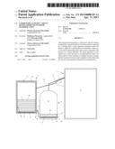
[0015] FIG. 1 shows a cross section through an incubator according to one embodiment of the present invention having connected steam generator.
DETAILED DESCRIPTION OF THE INVENTION
[0016] Referring now to the FIGURE, FIG. 1 illustrates an incubator 1 according to one embodiment of the present invention. The incubator 1 comprises a housing 2, which encloses an interior 3, in which, for example, microbiological samples can be stored under predefined temperature, humidity, and gas atmospheric conditions. Typical storage conditions for the samples are, for example, a temperature of 37° C. and an ambient humidity of approximately 95%. The interior 3 is closable by a door (not visible in the cross section). The internal equipment such as support floors, measuring devices, etc. has been left out for simplification.
[0017] To generate the humidity required in the interior 3, a steam generator 4 is connected via a steam feed line 7 to the incubator 1. The steam generator 4 consists of a container having a base region 40, which can accommodate a water reservoir 6, and a steam chamber 42 located above it, designed here in the form of a cupola. Water steam is generated in the steam generator 4 by heating the water reservoir 6 by means of a heating device 5 and fed from the steam chamber 42 via the steam feed line 7, which leaves the steam generator at the highest point of the steam chamber 42, to the interior 3 of the incubator 1. The steam feed line 7 is closed using a valve 71, which is always opened in a way known per se when the humidity and temperature values measured in the interior 3 fall below predefined target values. After reaching the target values, the valve 71 is closed again and the steam supply is interrupted.
[0018] The steam generator 4 is connected via a water feed line 8 in the form of an unstopped tube, which leads out of its base region 40, to a water container 9 and is arranged so that the base 41 of the steam generator 4 is located above the base 91 of the water container 9. The water feed line 8 leads out of a base region 90 of the water container 9. The water reservoir 6 is thus distributed to the steam generator 4 and the water container 9. If the water reservoir 6 in the steam generator is heated by operating the heating device 5, preferably to approximately 100° C., water steam forms and fills the steam chamber 42. The pressure thus rises in the steam generator 4, the water level 60' sinks, and water is displaced out of the steam generator 4 via the water feed line 8 into the water container 9. The water level 60 rises therein. FIG. 1 shows this, i.e., a state during the generation of water steam in the steam generator 4. The steam pressure in the steam generator 4 corresponds to the water column which stands above the water level 60', i.e., the difference of the water levels 60 and 60' (height h).
[0019] The arrangement of the water container 9 relative to the steam generator is such that under normal circumstances, the water standing in the water feed line 8 is not displaced completely out of the line. Steam which possibly penetrates into the water feed line 8 comes into contact with the colder water in the line 8, cools down, and condenses out, whereby the pressure sinks. To equalize very high overpressures, a pressure compensation opening 13 is additionally provided in the water container 9, through which the steam nonetheless possibly penetrating into the water container 9 can escape. Steam explosions are safely avoided in this manner.
[0020] The water reservoir 6 in the water container 9 fundamentally does not have to be heated at all. In the case shown, however a heating device 5' is provided, using which the water reservoir 6 can also be heated in the water container 9, although to a lower temperature than in the steam generator 4. It is preferably heated to a temperature of at least 60° C., particularly preferably 80 to 90° C. The higher the temperature of the water reservoir 6, the lower the probability that microbes will grow in the water, and the lower the heating power needed to bring water to a boil in the steam generator 4. The temperature of the water reservoir 6 in the water container 9 is not to be so high that water begins to boil therein, however. The temperature is monitored using a PTC element 10', which is connected (not shown here) to the power supply of the heating device 5'. The temperature control in the steam generator 4 is performed similarly using a PTC element 10. In order to decrease the heat loss, the water container 9 is provided with an insulation 92.
[0021] During the supply of water steam under pressure, the problem frequently occurred in the prior art that water condensed out in the steam feed line was entrained by a steam surge into the interior of the incubator and sprayed therein and then precipitated on the samples. In the incubator according to the present invention, this is prevented in that the steam feed line 7 is arranged rising diagonally in the direction toward the interior 3. Condensed water thus does not run into the interior 3, but rather in the direction back toward the steam generator 4. In order that it does not collect in front of the valve 71, a return line 72 is additionally provided, which branches downward out of the steam feed line 7 between valve 71 and inlet into the incubator and leads back into the water container 9. In addition, the region of the steam feed line 7 between valve 71 and incubator 1 is provided with an insulation 73, which can also be a heating sleeve, to prevent water from condensing out here as much as possible.
[0022] While the present invention has been illustrated by description of various embodiments and while those embodiments have been described in considerable detail, it is not the intention of Applicants to restrict or in any way limit the scope of the appended claims to such details. Additional advantages and modifications will readily appear to those skilled in the art. The invention in its broader aspects is therefore not limited to the specific details and illustrative examples shown and described. Accordingly, departures may be made from such details without departing from the spirit or scope of Applicants' invention.
User Contributions:
Comment about this patent or add new information about this topic:
Images included with this patent application:
 |  |
| Similar patent applications: | |
| Date | Title |
|---|---|
| 2013-07-04 | Corner improvement in window carrier for crack window |
| 2013-07-25 | Enclosed television with improved cable cover sealing mechanism |
| 2011-06-23 | Housing having a burglar-proof door hinge |
| 2012-05-31 | Apparatus on which fan can be mounted |
| 2012-11-15 | Drawer which can be dismantled and stacked |
| New patent applications from these inventors: | |
| Date | Title |
|---|---|
| 2015-02-26 | Thermal conductivity detector comprising a sealed cavity |
| 2015-02-19 | Laboratory incubator having improved moisture distribution |
| 2013-06-13 | Method for cleaning the usable space of a climatic cabinet |
| 2013-02-28 | Laboratory incubator having improved interior humidification |
| Top Inventors for class "Supports: cabinet structure" | |
| Rank | Inventor's name |
|---|---|
| 1 | Yun-Lung Chen |
| 2 | Karl-Friedrich Laible |
| 3 | Jae Hoon Lim |
| 4 | Wen-Tang Peng |
| 5 | Chen-Lu Fan |