Patent application title: IN SHOWER MAKE-UP REMOVER
Inventors:
Joanna Paulina Kozlowski (Denver, CO, US)
IPC8 Class: AA47L1310FI
USPC Class:
152101
Class name: Fabric wiper, dauber, or polisher special work
Publication date: 2013-03-21
Patent application number: 20130067672
Abstract:
One example embodiment includes an in shower make-up remover. The in
shower make-up remover includes a central chamber. The in shower make-up
remover also includes a pad, wherein the pad is releasably attached to
the central chamber.Claims:
1. An in shower make-up remover, the in shower make-up remover
comprising: a central chamber; and a pad, wherein the pad is releasably
attached to the central chamber.
2. The in shower make-up remover of claim 1, wherein the central chamber is configured to receive a cleanser tube.
3. The in shower make-up remover of claim 2, wherein the central chamber includes a cavity.
4. The in shower make-up remover of claim 1, wherein the central chamber includes an attachment configured to releasably attach the pad.
5. The in shower make-up remover of claim 1, wherein the pad includes one or more holes.
6. The in shower make-up remover of claim 5, wherein the one or more holes are configured to allow a cleanser to be extruded from the central chamber through the pad.
7. The in shower make-up remover of claim 6, further comprising a dial.
8. The in shower make-up remover of claim 7, wherein the dial is configured to allow the user to control the amount of cleanser extruded through the pad.
9. The in shower make-up remover of claim 7, wherein the dial is configured to move relative to the central chamber.
10. An in shower make-up remover, the in shower make-up remover comprising: a central chamber; and a cleanser tube located within the central chamber; a first pad; a first attachment configured to releasably attach the first pad to a first end of the central chamber; a second pad; a second attachment configured to releasably attach the second pad to a second end of the central chamber; and a dial, wherein the dial is configured to allow a user to release cleanser from the cleanser tube.
11. The in shower make-up remover of claim 10, wherein the first pad includes a partition.
12. The in shower make-up remover of claim 11, wherein the partition includes a plastic strip.
13. The in shower make-up remover of claim 10, wherein the first pad includes a tapered edge.
14. The in shower make-up remover of claim 10 further comprising a cap configured to: releasably attach to the first end of the central chamber; and enclose the first pad.
15. The in shower make-up remover of claim 0 further comprising a second cap configured to: releasably attach to the second end of the central chamber; and enclose the second pad.
16. An in shower make-up remover, the in shower make-up remover comprising: a central chamber; and a cleanser tube located within the central chamber; a first pad; a first attachment configured to releasably attach the first pad to a first end of the central chamber; a second pad; a second attachment configured to releasably attach the second pad to a second end of the central chamber; and a dial configured to: move relative to the central chamber; and allow a user to release cleanser from the cleanser tube.
17. The in shower make-up remover of claim 16, wherein the first cap includes clear plastic.
18. The in shower make-up remover of claim 17, wherein the second cap includes clear plastic.
19. The in shower make-up remover of claim 16 further comprising a divider located within the central housing.
20. The in shower make-up remover of claim 16, wherein the divider is: attached to the dial; and configured to: move relative to the central housing; and apply pressure to the cleanser tube, causing cleanser to be extruded from the tube.
Description:
CROSS-REFERENCE TO RELATED APPLICATIONS
[0001] This application claims the benefit of and priority to U.S. Provisional Patent Application Ser. No. 61/535,868 filed on Sep. 16, 2011, which application is incorporated herein by reference in its entirety.
BACKGROUND OF THE INVENTION
[0002] Cleaning make-up or other dirt from a user's face is often an uncomfortable process. In particular, the skin the area can be quite sensitive. This means that if the material used for cleaning is rough, it can cause the user pain or discomfort. Consequently, many users use fingers rather than cloths the clean their face, meaning that they do not get their face as clean as they could otherwise. In addition, the facial cleansers may contain harsh chemicals that cause the user discomfort. For example, the chemicals may irritate the user's skin or the fumes may irritate the user's eyes and/or nose.
[0003] Because of these drawbacks, a user may wash his/her face in a shower or bath. The water helps to reduce the friction during application, removes the cleanser quickly when the user is done and eases the application of the cleanser. However, there are problems with using cleaning instruments in a shower or bath. In particular, if the cleaning instrument stays wet, it may grow mildew or mold, ruining the cleaning instrument.
[0004] Accordingly, there is a need in the art for a cleaning instrument which is soft on a user's skin. In addition, there is a need in the art for the cleaning instrument to apply the cleanser only to desired areas. Further, there is need in the art for the cleaning instrument to be available for shower or bath use without remaining wet.
BRIEF SUMMARY OF SOME EXAMPLE EMBODIMENTS
[0005] This Summary is provided to introduce a selection of concepts in a simplified form that are further described below in the Detailed Description. This Summary is not intended to identify key features or essential characteristics of the claimed subject matter, nor is it intended to be used as an aid in determining the scope of the claimed subject matter.
[0006] One example embodiment includes an in shower make-up remover. The in shower make-up remover includes a central chamber. The in shower make-up remover also includes a pad, wherein the pad is releasably attached to the central chamber.
[0007] Another example embodiment includes an in shower make-up remover. The in shower make-up remover includes a central chamber. The in shower make-up remover also includes a cleanser tube located within the central chamber. The in shower make-up remover further includes a first pad. The in shower make-up remover additionally includes a first attachment configured to releasably attach the first pad to a first end of the central chamber. The in shower make-up remover moreover includes a second pad. The in shower make-up remover also includes a second attachment configured to releasably attach the second pad to a second end of the central chamber. The in shower make-up remover further includes a dial, wherein the dial is configured to allow a user to release cleanser from the cleanser tube.
[0008] Another example embodiment includes an in shower make-up remover. The in shower make-up remover includes a central chamber. The in shower make-up remover also includes a cleanser tube located within the central chamber. The in shower make-up remover further includes a first pad. The in shower make-up remover additionally includes a first attachment configured to releasably attach the first pad to a first end of the central chamber. The in shower make-up remover moreover includes a second pad. The in shower make-up remover also includes a second attachment configured to releasably attach the second pad to a second end of the central chamber. The in shower make-up remover further includes a dial, wherein the dial is configured to move relative to the central chamber and allow a user to release cleanser from the cleanser tube.
[0009] These and other objects and features of the present invention will become more fully apparent from the following description and appended claims, or may be learned by the practice of the invention as set forth hereinafter.
BRIEF DESCRIPTION OF THE DRAWINGS
[0010] To further clarify various aspects of some example embodiments of the present invention, a more particular description of the invention will be rendered by reference to specific embodiments thereof which are illustrated in the appended drawings. It is appreciated that these drawings depict only illustrated embodiments of the invention and are therefore not to be considered limiting of its scope. The invention will be described and explained with additional specificity and detail through the use of the accompanying drawings in which:
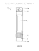
[0011] FIG. 1A illustrates a side view of an example of an in shower make-up remover;
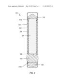
[0012] FIG. 1B illustrates an exploded perspective view of an example of an in shower make-up remover;
[0013] FIG. 2 illustrates a cutaway view of the in shower make-up remover;
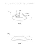
[0014] FIG. 3 illustrates a perspective view of an example of a first pad; and
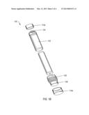
[0015] FIG. 4 illustrates a perspective view of an example of second pad.
DETAILED DESCRIPTION OF SOME EXAMPLE EMBODIMENTS
[0016] Reference will now be made to the figures wherein like structures will be provided with like reference designations. It is understood that the figures are diagrammatic and schematic representations of some embodiments of the invention, and are not limiting of the present invention, nor are they necessarily drawn to scale.
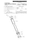
[0017] FIGS. 1A and 1B illustrate an example of an in shower make-up remover 100. FIG. 1A illustrates a side view of an example of an in shower make-up remover; and FIG. 1B illustrates an exploded perspective view of an example of an in shower make-up remover. The in shower make-up remover 100 can allow a user to clean his/her face and/or apply moisturizer. In particular, the in shower make-up remover 100 can include cleansing pads and cleanser in an easy to use combination.
[0018] FIGS. 1A and 1B show that the in shower make-up remover 100 can include a central chamber 102. The central chamber 102 can store cleanser or other desired materials. Additionally or alternatively, the central chamber 102 can provide structure and support to the other elements of the in shower make-up remover 100. I.e., the other elements of the in shower make-up remover 100 can be attached to or mounted on the central chamber 102.
[0019] FIGS. 1A and 1B also show that the in shower make-up remover 100 can include a first pad 104. The first pad 104 can allow the user to do minor facial cleansing. In particular, the first pad 104 can be infused with a cleanser or other desired cleanser. The first pad 104 can then be rubbed on the area that the user desires to clean.
[0020] FIGS. 1A and 1B further show that the in shower make-up remover 100 can include a dial 106. The dial 106 can move relative to the central chamber 102. As the dial 106 is moved by the user, it can allow the user to extrude the cleanser. In particular, as the dial 106 is moved a desired direction, it can force cleanser into or through the first pad 104.
[0021] FIGS. 1A and 1B additionally show that the in shower make-up remover 100 can include a second pad 108. The second pad 108 can allow the user to do deeper cleansing. For example, the second pad 108 can include disposable pads that include face cleansers. Additionally or alternatively, the second pad 108 can include a thick pad that can have cleanser added. The second pad 108 can be mounted on the central chamber 102 opposite the first pad 104.
[0022] FIGS. 1A and 1B moreover show that the in shower make-up remover 100 can include a first cap 110a and a second cap 110b (collectively "caps 110") which can protect the first pad 104 and the second pad 108, respectively. For example, the caps 110 can be releasably attached to the central chamber 102 such that they prevent water or other debris from getting on the first pad 104 and/or the second pad 108.
[0023] FIG. 2 illustrates a cutaway view of the in shower make-up remover 100. The in shower make-up remover 100 can include internal components that allow the user to apply cleanser as desired. In particular, the in shower make-up remover 100 can store the cleanser for the user, as described below.
[0024] FIG. 2 shows that the central chamber 102 can include a cavity 202. The cavity 202 can be configured to receive a cleanser. For example, the cleanser can be added directly to the cavity 202. Additionally or alternatively, the cleanser can be added in a container which is inserted into the cavity 202.
[0025] FIG. 2 shows that the central chamber 102 can include a cleanser tube 204. The cleanser tube 204 can hold the cleanser to be applied to the first pad 104. The cleanser tube 204 can be replaceable. Additionally or alternatively, the cleanser tube 204 can include an opening to allow the user to insert additional cleanser.
[0026] FIG. 2 also shows that the in shower make-up remover 100 can include a cleanser 206. The cleanser 206 can be stored until desired by the user. In particular, the cleanser 206 can be stored and extrude by the user as desired. The cleanser 206 can include any desired cleanser. For example, the cleanser 206 can include a moisturizing cleanser or any other desired cleanser.
[0027] FIG. 2 also shows that the central chamber 102 can include a divider 208. The divider 208 can be configured to push cleanser from the cleanser tube 204. In particular, the divider 208 can be moved by the dial 106 to control the amount of cleanser which is extruded from the cleanser tube 204. For example, the divider 208 can reduce the size of the cleanser tube 204. Additionally or alternatively, the divider 208 can apply pressure to a portion of the cleanser tube 204, causing cleanser to extrude from the cleanser tube 204.
[0028] FIG. 2 further shows that the central chamber 102 can also include a first attachment 210a and a second attachment 210b (collectively "attachments 210") which can allow the first pad 104 and the second pad 108, respectively, to be releasably attached to the central chamber 102. For example, the attachments 210 can include a threaded connection, a flange, a snap, hook and loop fasteners or any other desired attachment mechanism.
[0029] FIG. 3 illustrates a perspective view of an example of a first pad 104. The first pad 104 can be used to do light cleansing. In particular, the first pad 104 can allow a user to apply cleanser and clean an area simultaneously. Additionally or alternatively, the first pad 104 can allow the user to reach area, such as eye creases, that are difficult to reach with other materials, as described below.
[0030] FIG. 3 shows that the first pad 104 can include a body 302. The body 302 can be configured to attach to the central chamber of an in shower make-up remover or some other device. For example, the body 302 can include one or more mechanisms to mate with an attachment on the desired device. Additionally or alternatively, the body 302 can include padding or other material to make sure that the user does not hurt himself/herself during use.
[0031] FIG. 3 also shows that the first pad 104 can include a cleansing portion 304. The cleansing portion 304 can include soft material which is configured to be rubbed on the skin of the user. For example, the cleansing portion 304 can include cotton or other materials. Additionally or alternatively, the cleansing portion 304 can include an absorbing material. The absorbing material can be configured to absorb oils, cleansers, water, make-up or other materials.
[0032] FIG. 3 further shows that the cleansing portion 304 can include a tapered edge 306. In at least one implementation, the tapered edge 306 can allow the cleansing portion 304 to be inserted into eye creases or other hard to reach spots. I.e., the tapered edge 306 can allow the user to insert the cleansing portion 304 into a hard to reach area.
[0033] FIG. 3 additionally shows that the first pad 104 can include a partition 308. The partition 308 can allow the cleansing portion 304 to be divided into two or more areas, each designed to allow the user to perform a different cleansing function. The partition 308 can include a change of material, a plastic line, a change in shape or texture or any other desired partition.
[0034] FIG. 3 further shows that the first pad 104 can include one or more holes 310. The one or more holes 310 can allow the cleanser to be extruded through the first pad 104. In particular, the one or more holes 310 can allow the cleanser to be moved from behind the first pad 104 to the exterior to the exterior of the first pad 104 where it can be applied to the skin of the user.
[0035] FIG. 4 illustrates a perspective view of an example of second pad 108. The second pad 108 can allow a user to perform a deep cleaning of a desired area. In particular, the second pad 108 can be thicker than the first pad, allowing the user to scrub the area more vigorously.
[0036] FIG. 4 shows that the second pad 108 can include a body 402. The body 402 can be configured to attach to the central chamber of an in shower make-up remover or some other device. For example, the body 402 can include one or more mechanisms to mate with an attachment on the desired device. Additionally or alternatively, the body 402 can include padding or other material to make sure that the user does not hurt himself/herself during use.
[0037] FIG. 4 also shows that the second pad 108 can include a cleansing portion 404. The cleansing portion 404 can include soft material which is configured to be rubbed on the skin of the user. For example, the cleansing portion 404 can include cotton or other materials. Additionally or alternatively, the cleansing portion 404 can include an absorbing material. The absorbing material can be configured to absorb oils, cleansers, water, make-up or other materials.
[0038] The present invention may be embodied in other specific forms without departing from its spirit or essential characteristics. The described embodiments are to be considered in all respects only as illustrative and not restrictive. The scope of the invention is, therefore, indicated by the appended claims rather than by the foregoing description. All changes which come within the meaning and range of equivalency of the claims are to be embraced within their scope.
User Contributions:
Comment about this patent or add new information about this topic:
Images included with this patent application:
 |  |
 |  |
 |
| Similar patent applications: | |
| Date | Title |
|---|---|
| 2013-08-08 | Make-up removal wipe |
| 2011-06-23 | Sponge type make-up brush |
| 2012-08-16 | Snow booger remover |
| 2013-06-20 | Debris shredding pick-up head system |
| New patent applications in this class: | |
| Date | Title |
|---|---|
| 2016-12-29 | Vehicle interior detailing tool |
| 2016-06-23 | Wiping board apparatus |
| 2016-06-16 | Oscillating fiber optic cleaning tool |
| 2016-05-19 | Back and body washing device |
| 2016-05-12 | Facial cleansing pad |
| Top Inventors for class "Brushing, scrubbing, and general cleaning" | |
| Rank | Inventor's name |
|---|---|
| 1 | Wayne Ernest Conrad |
| 2 | Xavier Boland |
| 3 | Helmut Depondt |
| 4 | Robert Moskovich |
| 5 | James Dyson |