Patent application title: DATA CENTER WITH CABLE MANAGEMENT STRUCTURE
Inventors:
Wen-Tang Peng (Tu-Cheng, TW)
Yi-Liang Hsiao (Tu-Cheng, TW)
Yi-Liang Hsiao (Tu-Cheng, TW)
Assignees:
HON HAI PRECISION INDUSTRY CO., LTD.
IPC8 Class: AH05K500FI
USPC Class:
361724
Class name: Housing or mounting assemblies with diverse electrical components for electronic systems and devices cabinet-type housing
Publication date: 2013-01-24
Patent application number: 20130021756
Abstract:
A data center includes a housing and a number of server units arranged in
the housing. Each server unit includes a server module and a cable
management member. The first ends of a number of cables are connected to
the back panel of the server module. The cable management member includes
a bottom plate, a front plate, and two side plates. A number of
connectors are set on the front plate. The second ends of the cables are
connected to the connectors. The cable management member is fixed to one
side of the server module. The cables are received in a space formed
between the bottom plate of the cable management member and the server
module.Claims:
1. A data center comprising: a housing; and a plurality of server units
received in the housing, wherein each of the server units comprises a
server module and a cable management member fixed to one side of the
server module; the server module comprises a front panel, a back panel,
and two opposite sidewalls connected between the front panel and the back
panel; the cable management member comprises a bottom plate, a front
plate extending from a front end of the bottom plate, and two side plates
extending from opposite sides of the bottom plate, a plurality of
connectors is set on the front plate, first ends of a plurality of cables
are electrically connected to the back panel, second ends of the cables
are connected to the connectors, the front plate is coplanar with the
front panel, the side plates are coplanar with the sidewalls
respectively, the cables are received in a space formed between the
bottom plate of the cable management member and the server module.
2. The data center of claim 1, wherein a plurality of supporting pieces extend inward from each of the side plates, the server module is supported on the supporting pieces.
3. The data center of claim 2, wherein a plurality of mounting holes are defined in the sidewalls of the server module, a plurality of blocking pieces extend up from each side plate, each of the blocking pieces defines a through hole, a plurality of screws extend through the through holes of the blocking pieces to screw into the mounting holes of the server module.
Description:
BACKGROUND
[0001] 1. Technical Field
[0002] The disclosure generally relates to data centers; and more particularly to a data center having a cable management structure.
[0003] A data center usually includes a plurality of connectors set on the front side of the data center. However, electronic devices, such as servers, arranged in the data center often include cables extending from backs of the electronic devices creating messy wire runs when connected to the connectors.
BRIEF DESCRIPTION OF THE DRAWINGS
[0004] Many aspects of the present embodiments can be better understood with reference to the following drawings. The components in the drawings are not necessarily drawn to scale, the emphasis instead being placed upon clearly illustrating the principles of the present embodiments. Moreover, in the drawings, like reference numerals designate corresponding parts throughout the several views.
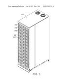
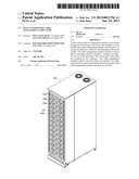
[0005] FIG. 1 is an assembled view of a data center, which includes a plurality of server units, in accordance with an embodiment.
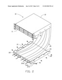
[0006] FIG. 2 is an exploded, isometric view of one of the server units of FIG. 1.
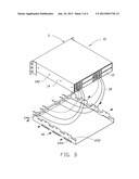
[0007] FIG. 3 is similar to FIG. 2, but viewed from a different aspect.
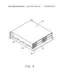
[0008] FIG. 4 is an assembled view of FIG. 3.
DETAILED DESCRIPTION
[0009] The disclosure, including the accompanying drawings, is illustrated by way of examples and not by way of limitation. It should be noted that references to "an" or "one" embodiment in this disclosure are not necessarily to the same embodiment, and such references mean at least one.
[0010] Referring to FIG. 1, an exemplary embodiment of a data center includes a housing 100 and a plurality of server units 200 received in the housing 100.
[0011] Referring to FIG. 2 and FIG. 3, each server unit 200 includes a server module 10 and a cable management member 20. The server module 10 includes a front panel 11, a back panel 12 electrically connected to electronic components of the server modules 10, and two opposite sidewalls 14 connected between the front panel 11 and the back panel 12. First ends of a plurality of cables 30 are electrically connected to the back panel 12. A plurality of mounting holes 142 is defined in the sidewalls 14.
[0012] The cable management member 20 includes a bottom plate 21, a front plate 22 extending from a front end of the bottom plate 21, and two side plates 24 extending from opposite sides of the bottom plate 21. A plurality of connectors 222 is set on the front plate 22. A plurality of supporting pieces 242 perpendicularly extend inward from a top of each side plate 24. A plurality of blocking pieces 244 extend up from the top of each side plate 24. Each blocking piece 244 defines a through hole 246.
[0013] Referring to FIG. 4, in assembly, second ends of the cables 30 are connected to the connectors 222. The server module 10 is supported on the supporting pieces 242 of the cable management member 20. The blocking pieces 244 block the corresponding sidewalls 14. A plurality of screws 40 extends through the through holes 246 to screw into the mounting holes 142 of the server module 10. The front plate 22 is coplanar with the front panel 11. The side plates 24 are coplanar with the sidewalls 14 respectively. The cables 30 are received in a space formed between the bottom plate 21 and the server module 10.
[0014] Obviously, the cable management member 20 can be fixed either to a top of the server module 10 or one sidewall 14 of the server module 10.
[0015] Referring to FIG. 1, the assembled server unit 200 is then received in the housing 100. In this data center, the cables 30 extend through the cable management member 20 to connect the back panel 12 to the connectors 222 of the front plate 22, which maintains the cables 30 in an orderly manner.
[0016] Even though numerous characteristics and advantages of the embodiments have been set forth in the foregoing description, together with details of the structure and function of the embodiments, the disclosure is illustrative only, and changes may be made in detail, especially in the matters of shape, size, and arrangement of parts within the principles of the present disclosure to the full extent indicated by the broad general meaning of the terms in which the appended claims are expressed.
User Contributions:
Comment about this patent or add new information about this topic:
Images included with this patent application:
 |  |
 |  |
 |
| Similar patent applications: | |
| Date | Title |
|---|---|
| 2012-11-22 | Rack mounted computer system and cable management mechanism thereof |
| 2012-11-22 | High energy density storage material device using nanochannel structure |
| 2012-09-13 | Foundation member with cable theft deterrent device |
| 2012-11-15 | Board-level package with tuned mass damping structure |
| 2012-11-08 | Non-flat panel display module and back frame support structure thereof |
| New patent applications in this class: | |
| Date | Title |
|---|---|
| 2019-05-16 | Accommodation box and electronic component unit |
| 2016-12-29 | Wireless access device isolation cabinet |
| 2016-06-23 | Docking station |
| 2016-05-19 | Pivoting equipment mounting bracket |
| 2016-05-12 | Electronic device |
| New patent applications from these inventors: | |
| Date | Title |
|---|---|
| 2013-12-26 | Fastening device for hard disk drive |
| 2013-12-26 | Fastening device for hard disk drive |
| 2013-11-28 | Power distribution unit and server cabinet with the power distribution unit |
| 2013-10-03 | Server assembly with removable server module |
| 2013-06-27 | Server assembly and rack of the same |
| Top Inventors for class "Electricity: electrical systems and devices" | |
| Rank | Inventor's name |
|---|---|
| 1 | Zheng-Heng Sun |
| 2 | Levi A. Campbell |
| 3 | Li-Ping Chen |
| 4 | Robert E. Simons |
| 5 | Richard C. Chu |