Patent application title: DOCUMENT POSITION-LIMITING MECHANISM
Inventors:
Wei-Hsun Hsu (Taipei, TW)
Assignees:
PRIMAX ELECTRONICS LTD.
IPC8 Class: AB65H100FI
USPC Class:
271171
Class name: Feeding pack holders holder adjustable to size of sheet
Publication date: 2013-01-03
Patent application number: 20130001866
Abstract:
A document position-limiting mechanism includes a first paper guide
plate, a second paper guide plate, a connecting wheel and a switching
module. The first paper guide plate and the second paper guide plate are
used for guiding a document on a paper input tray to be fed into an
automatic document feeder. Through the connecting wheel, the first paper
guide plate and the second paper guide plate are movable on the paper
input tray. Via the switching module, the document position-limiting
mechanism can be operated in two operating modes to be selected by the
user in order to meet the requirements of different users.Claims:
1. A document position-limiting mechanism for use in a paper input tray
of an automatic document feeder, said document position-limiting
mechanism comprising: a first paper guide plate disposed on said paper
input tray for guiding a document to be fed into said automatic document
feeder, wherein said first paper guide plate has an extension arm; a
second paper guide plate located at a side of said first paper guide
plate for guiding said document to be fed into said automatic document
feeder, wherein said second paper guide plate is movable in a direction
opposite to a moving direction of said first paper guide plate; a
connecting wheel arranged between said first paper guide plate and said
second paper guide plate, and respectively engaged with said first paper
guide plate and said second paper guide plate, so that said second paper
guide plate is movable in said direction opposite to said moving
direction of said first paper guide plate; and a switching module
disposed on said paper input tray for switching an operating mode of said
document position-limiting mechanism from a manual positioning mode to a
graduation positioning mode or from said graduation positioning mode to
said manual positioning mode, wherein said switching module comprises: a
driving part comprising a switching button, which is exposed to said
paper input tray, wherein said switching module is driven by operating
said switching button; and a positioning plate located adjacent to said
driving part, and comprising a plurality of recesses, wherein as said
switching button is moved, said positioning plate is pushed by said
driving part so as to be moved with said switching button, wherein when
said extension arm is inserted into one of said recesses, said document
position-limiting mechanism is operated in said graduation positioning
mode, wherein when said extension arm is disengaged from said recesses,
said document position-limiting mechanism is operated in said manual
positioning mode.
2. The document position-limiting mechanism according to claim 1 wherein said positioning plate further comprises a plurality of sliding grooves, and said paper input tray further comprises a plurality of positioning posts, wherein said positioning posts are disposed on an inner surface of said paper input tray and penetrated through respective sliding grooves, wherein when said switching button is moved in a first direction, said positioning plate is pushed by said driving part to be moved in a second direction along said sliding grooves.
3. The document position-limiting mechanism according to claim 2 wherein an included angle between said first direction and said second direction is 45 degrees.
4. The document position-limiting mechanism according to claim 2 wherein when said first paper guide plate is moved in a third direction, said second paper guide plate is moved in a fourth direction opposite to said third direction, wherein said first direction is perpendicular to said third direction and said fourth direction.
5. The document position-limiting mechanism according to claim 1 wherein said extension arm has a protrusion, which is located at an end of said extension arm, wherein when said document position-limiting mechanism is operated in said graduation positioning mode, said protrusion is inserted into one of said recesses.
6. The document position-limiting mechanism according to claim 5 wherein said first paper guide plate further comprises a first paper stopper and a first rack, and said second paper guide plate further comprises a second paper stopper and a second rack, wherein said first paper stopper is exposed to an outer surface of said paper input tray for stopping a first edge of said document, said first rack is connected with said first paper stopper and engaged with said connecting wheel, said second paper stopper is exposed to said outer surface of said paper input tray for stopping a second edge of said document, and said second rack is connected with said second paper stopper and engaged with said connecting wheel.
7. The document position-limiting mechanism according to claim 6 wherein said extension arm and said protrusion are integrally formed with said first rack.
8. The document position-limiting mechanism according to claim 6 wherein said connecting wheel further comprises: a wheel body disposed on said inner surface of said paper input tray; and a plurality of toothed structures disposed on said wheel body and engaged with said first rack and said second rack, so that the wheel body is rotatable relative to said first rack and said second rack.
9. The document position-limiting mechanism according to claim 1 wherein said driving part further comprises a fixing bulge, and said paper input tray further comprises a first positioning notch and a second positioning notch, wherein said fixing bulge is disposed on an inner surface of said paper input tray, said first positioning notch is located at a first side of said inner surface of said paper input tray, and said second positioning notch is located at said first side of said inner surface of said paper input tray and adjacent to said first positioning notch, wherein when said document position-limiting mechanism is operated in said manual positioning mode, said fixing bulge is inserted into said first positioning notch, wherein when said document position-limiting mechanism is operated in said graduation positioning mode, said fixing bulge is inserted into said second positioning notch.
10. The document position-limiting mechanism according to claim 9 wherein said fixing bulge and said switching button are integrally formed with said driving part.
Description:
FIELD OF THE INVENTION
[0001] The present invention relates to a document position-limiting mechanism, and more particularly to a document position-limiting mechanism for use in a paper input tray of an automatic document feeder.
BACKGROUND OF THE INVENTION
[0002] Generally, an automatic document feeder and an image scanner are collectively defined as an automatic scanning apparatus to automatically scanning a plurality of paper sheets. Moreover, an automatic document feeder and a printer are collectively defined as an automatic printing apparatus. The automatic document feeder can be used for feeding various documents with different sizes. For example, the automatic document feeder is widely employed to feed the A4-sized documents. As known, if the document is not confined at the middle region of the paper input tray, the document is readily aslant fed into the internal portion of the automatic document feeder. Under this circumstance, the scanning operation or the printing operation is usually incomplete. For solving this drawback, the paper input tray of the automatic document feeder is usually equipped with a document position-limiting mechanism for confining the document at the middle region of the paper input tray.
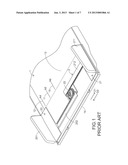
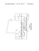
[0003] FIG. 1 is a schematic perspective illustrating a document position-limiting mechanism installed on a paper input tray of an automatic document feeder according to the prior art. The document position-limiting mechanism 2 is applied to a paper input tray 1 of an automatic document feeder. The paper input tray 1 has a plurality of graduations 10, 11 and 12. These graduations 10, 11 and 12 are located at a first side of the document position-limiting mechanism 2. In addition, the graduations 10, 11 and 12 are shown on an outer surface 13 of the paper input tray 1, and arranged in a line. A first graduation 10 of these graduations corresponds to an A6-sized document. A second graduation 11 of these graduations corresponds to an A5-sized document. A third graduation 12 of these graduations corresponds to an A4-sized document.
[0004] The document position-limiting mechanism 2 comprises a first paper guide plate 20, a second paper guide plate 21 and a connecting wheel 22. The first paper guide plate 20 is disposed on the paper input tray 1. In addition, the first paper guide plate 20 comprises a first paper stopper 201 and a first rack 202. The first paper stopper 201 is exposed to the outer surface 13 of the paper input tray 1 for stopping a first edge of a document (not shown). The first rack 202 is disposed on an inner surface 14 of the paper input tray 1 and in contact with the connecting wheel 22.
[0005] Similarly, the second paper guide plate 21 is disposed on the paper input tray 1 and located at a side of the first paper guide plate 20. In addition, the second paper guide plate 21 comprises a second paper stopper 211 and a second rack 212. The second paper stopper 211 is exposed to the outer surface 13 of the paper input tray 1 for stopping a second edge of the document. The second rack 212 is disposed on the inner surface 14 of the paper input tray 1 and in contact with the connecting wheel 22. The connecting wheel 22 is arranged between the first paper guide plate 20 and the second paper guide plate 21, and contacted with and engaged with the first rack 202 of the first paper guide plate 20 and the second rack 212 of the second paper guide plate 21, respectively. Consequently, the first paper guide plate 20 and the second paper guide plate 21 are moved in opposite directions. That is, as the first paper guide plate 20 is moved in a first direction D1, the second paper guide plate 21 is moved in a second direction D2 opposite to the first direction D1 through the connecting wheel 22, and vice versa.
[0006] When the user wants to scan an A4-sized document, the document position-limiting mechanism 2 should be firstly adjusted to comply with the A4-sized document. The method of adjusting the document position-limiting mechanism 2 comprises the following steps. First of all, the first paper guide plate 20 is moved to the location corresponding to the third graduation 12 while the first paper guide plate 20 is aligned with the third graduation 12 by naked eyes. In response to movement of the first paper guide plate 20, the second paper guide plate 21 is moved to a corresponding location. Then, the A4-sized document is placed on the document position-limiting mechanism 2. Meanwhile, the first edge of the document is stopped by the first paper stopper 201 of the first paper guide plate 20, and the second edge of the document is stopped by the second paper stopper 211 of the second paper guide plate 21. In such way, the document will not be aslant fed into the internal portion of the automatic document feeder.
[0007] From the above discussions, the document position-limiting mechanism 2 has a plurality of graduations 10, 11 and 12. Before the document to be fed is placed on the paper input tray 1, the relative locations of the first paper guide plate 20 and the second paper guide plate 21 are adjusted according to the size of the document and the graduations 10, 11 and 12. Since the ways of recognizing the location of the graduation and aligning the first paper guide plate 20 with the graduation are very inconvenient to many users, another document position-limiting mechanism without the need of using the naked eyes to align the graduation is disclosed.
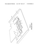
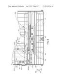
[0008] FIG. 2 is a schematic perspective illustrating another document position-limiting mechanism installed on a paper input tray of an automatic document feeder according to the prior art. FIG. 3 is a schematic bottom view illustrating the document position-limiting mechanism of FIG. 2. Please refer to FIGS. 2 and 3. The document position-limiting mechanism 4 is applied to a paper input tray 3 of an automatic document feeder. The paper input tray 3 has a plurality of graduations 30, 31 and 32. These graduations 30, 31 and 32 are located at a first side of the document position-limiting mechanism 4. In addition, the graduations 30, 31 and 32 are shown on an outer surface 33 of the paper input tray 3, and arranged in a line. A first graduation 30 of these graduations corresponds to an A6-sized document. A second graduation 31 of these graduations corresponds to an AS-sized document. A third graduation 32 of these graduations corresponds to an A4-sized document. As shown in FIG. 3, the paper input tray 3 further comprises a plurality of recesses 35, 36 and 37. These recesses 35, 36 and 37 are located at an inner surface 34 of the paper input tray 3. The first recess 35 of these recesses is aligned the first graduation 30. The second recess 36 of these recesses is aligned with the second graduation 31. The third recess 37 of these recesses is aligned with the third graduation 32.
[0009] The document position-limiting mechanism 4 comprises a first paper guide plate 40, a second paper guide plate 41 and a connecting wheel 42. The first paper guide plate 40 is disposed on the paper input tray 3. In addition, the first paper guide plate 40 comprises a first paper stopper 401 and a first rack 402. The first paper stopper 401 is exposed to the outer surface 33 of the paper input tray 3 for stopping a first edge of a document (not shown). The first rack 402 is disposed on the inner surface 34 of the paper input tray 3 and in contact with the connecting wheel 42.
[0010] Similarly, the second paper guide plate 41 is disposed on the paper input tray 3 and located at a side of the first paper guide plate 40. In addition, the second paper guide plate 41 comprises a second paper stopper 411, a second rack 412 and a protrusion 413. The second paper stopper 411 is exposed to the outer surface 33 of the paper input tray 3 for stopping a second edge of the document. The second rack 412 is disposed on the inner surface 34 of the paper input tray 3 and in contact with the connecting wheel 42. The protrusion 413 is close to the recesses 35, 36 and 37 of the paper input tray 3. As the second paper guide plate 41 is moved, the protrusion 413 is selectively inserted into one of these recesses 35, 36 and 37. The connecting wheel 42 is arranged between the first paper guide plate 40 and the second paper guide plate 41, and contacted with and engaged with the first rack 402 of the first paper guide plate 40 and the second rack 412 of the second paper guide plate 41, respectively. Consequently, the first paper guide plate 40 and the second paper guide plate 41 are moved in opposite directions.
[0011] When the user wants to scan an A4-sized document, the document position-limiting mechanism 4 should be firstly adjusted to comply with the A4-sized document. The method of adjusting the document position-limiting mechanism 4 comprises the following steps. First of all, the location of the third graduation 32 corresponding to the A4-sized document is realized by the naked eyes. Then, the second paper guide plate 41 is moved toward the location of the third graduation 32. As the second paper guide plate 41 is moved, the protrusion 413 of the second paper guide plate 41 is inserted into the third recess 37 corresponding to the third graduation 32. Whereas, in response to movement of the second paper guide plate 41, the first paper guide plate 40 is moved to a corresponding location. Then, the A4-sized document is placed on the document position-limiting mechanism 4. Meanwhile, the first edge of the document is stopped by the first paper stopper 401 of the first paper guide plate 40, and the second edge of the document is stopped by the second paper stopper 411 of the second paper guide plate 41. In such way, the document will not be aslant fed into the internal portion of the automatic document feeder.
[0012] In the conventional document position-limiting mechanism 4, the location of the second paper guide plate 41 can be fixed when the protrusion 413 of the second paper guide plate 41 is inserted into one of the recesses 35, 36 and 37.
[0013] That is, the use of the document position-limiting mechanism 4 does not need to precisely align the graduations corresponding to various document sizes with the naked eyes. However, in comparison with the conventional document position-limiting mechanism 2 that can be applied to the documents of various sizes (including the unofficial document sizes), the conventional document position-limiting mechanism 4 is only used to confine the document of a special size (e.g. A4, A5 and A6). Therefore, there is need of providing a document position-limiting mechanism that is applicable to the documents of various sizes and can be easily operated without using the naked eyes to align the graduation.
SUMMARY OF THE INVENTION
[0014] The present invention provides a document position-limiting mechanism that is applicable to the documents of various sizes and can be easily operated without using the naked eyes to align the graduation.
[0015] In accordance with an aspect of the present invention, there is provided a document position-limiting mechanism for use in a paper input tray of an automatic document feeder. The document position-limiting mechanism includes a first paper guide plate, a second paper guide plate, a connecting wheel and a switching module. The first paper guide plate is disposed on the paper input tray for guiding a document to be fed into the automatic document feeder. In addition, the first paper guide plate has an extension arm. The second paper guide plate is located at a side of the first paper guide plate for guiding the document to be fed into the automatic document feeder. The second paper guide plate is movable in a direction opposite to a moving direction of the first paper guide plate. The connecting wheel is arranged between the first paper guide plate and the second paper guide plate, and respectively engaged with the first paper guide plate and the second paper guide plate, so that the second paper guide plate is movable in the direction opposite to the moving direction of the first paper guide plate. The switching module is disposed on the paper input tray for switching an operating mode of the document position-limiting mechanism from a manual positioning mode to a graduation positioning mode or from the graduation positioning mode to the manual positioning mode. The witching module includes a driving part and a positioning plate. The driving part includes a switching button, which is exposed to the paper input tray. The switching module is driven by operating the switching button. The positioning plate is located adjacent to the driving part, and includes a plurality of recesses. As the switching button is moved, the positioning plate is pushed by the driving part so as to be moved with the switching button. When the extension arm is inserted into one of the recesses, the document position-limiting mechanism is operated in the graduation positioning mode. Whereas, when the extension arm is disengaged from the recesses, the document position-limiting mechanism is operated in the manual positioning mode.
[0016] In an embodiment, the positioning plate further includes a plurality of sliding grooves, and the paper input tray further includes a plurality of positioning posts. The positioning posts are disposed on an inner surface of the paper input tray and penetrated through respective sliding grooves. When the switching button is moved in a first direction, the positioning plate is pushed by the driving part to be moved in a second direction along the sliding grooves.
[0017] In an embodiment, an included angle between the first direction and the second direction is 45 degrees.
[0018] In an embodiment, when the first paper guide plate is moved in a third direction, the second paper guide plate is moved in a fourth direction opposite to the third direction, wherein the first direction is perpendicular to the third direction and the fourth direction.
[0019] In an embodiment, the extension arm has a protrusion, which is located at an end of the extension arm. When the document position-limiting mechanism is operated in the graduation positioning mode, the protrusion is inserted into one of the recesses.
[0020] In an embodiment, the first paper guide plate further includes a first paper stopper and a first rack, and the second paper guide plate further includes a second paper stopper and a second rack. The first paper stopper is exposed to an outer surface of the paper input tray for stopping a first edge of the document. The first rack is connected with the first paper stopper and engaged with the connecting wheel. The second paper stopper is exposed to the outer surface of the paper input tray for stopping a second edge of the document. In addition, the second rack is connected with the second paper stopper and engaged with the connecting wheel.
[0021] In an embodiment, the extension arm and the protrusion are integrally formed with the first rack.
[0022] In an embodiment, the connecting wheel further includes a wheel body and a plurality of toothed structures. The wheel body is disposed on the inner surface of the paper input tray. The toothed structures are disposed on the wheel body and engaged with the first rack and the second rack, so that the wheel body is rotatable relative to the first rack and the second rack.
[0023] In an embodiment, the driving part further includes a fixing bulge, and the paper input tray further includes a first positioning notch and a second positioning notch. The fixing bulge is disposed on an inner surface of the paper input tray. The first positioning notch is located at a first side of the inner surface of the paper input tray. The second positioning notch is located at the first side of the inner surface of the paper input tray and adjacent to the first positioning notch. When the document position-limiting mechanism is operated in the manual positioning mode, the fixing bulge is inserted into the first positioning notch. Whereas, when the document position-limiting mechanism is operated in the graduation positioning mode, the fixing bulge is inserted into the second positioning notch.
[0024] In an embodiment, the fixing bulge and the switching button are integrally formed with the driving part.
[0025] The above objects and advantages of the present invention will become more readily apparent to those ordinarily skilled in the art after reviewing the following detailed description and accompanying drawings, in which:
BRIEF DESCRIPTION OF THE DRAWINGS
[0026] FIG. 1 is a schematic perspective illustrating a document position-limiting mechanism installed on a paper input tray of an automatic document feeder according to the prior art;
[0027] FIG. 2 is a schematic perspective illustrating another document position-limiting mechanism installed on a paper input tray of an automatic document feeder according to the prior art;
[0028] FIG. 3 is a schematic bottom view illustrating the document position-limiting mechanism of FIG. 2;
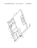
[0029] FIG. 4 is a schematic perspective illustrating a document position-limiting mechanism installed on a paper input tray of an automatic document feeder according to an embodiment of the present invention;
[0030] FIG. 5 is a schematic perspective illustrating the document position-limiting mechanism of FIG. 4 and taken along another viewpoint;
[0031] FIG. 6 is a schematic bottom view illustrating the document position-limiting mechanism according to the embodiment of the present invention, in which the document position-limiting mechanism is operated in a manual positioning mode; and
[0032] FIG. 7 is a schematic bottom view illustrating the document position-limiting mechanism according to the embodiment of the present invention, in which the document position-limiting mechanism is operated in a graduation positioning mode.
DETAILED DESCRIPTION OF THE PREFERRED EMBODIMENT
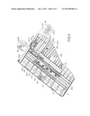
[0033] For obviating the drawbacks encountered from the prior art, the present invention provides a document position-limiting mechanism. FIG. 4 is a schematic perspective illustrating a document position-limiting mechanism installed on a paper input tray of an automatic document feeder according to an embodiment of the present invention. FIG. 5 is a schematic perspective illustrating the document position-limiting mechanism of FIG. 4 and taken along another viewpoint. Please refer to FIGS. 4 and 5. The document position-limiting mechanism 6 is applied to a paper input tray 5 of an automatic document feeder (not shown). The paper input tray 5 has a plurality of graduations 51, 52 and 53. These graduations 51, 52 and 53 are located at a first side of the document position-limiting mechanism 6. In addition, the graduations 51, 52 and 53 are shown on an outer surface 54 of the paper input tray 5, and arranged in a line. A first graduation 51 of these graduations corresponds to an A6-sized document. A second graduation 52 of these graduations corresponds to an AS-sized document. A third graduation 53 of these graduations corresponds to an A4-sized document.
[0034] Please refer to FIGS. 5 and 6. FIG. 6 is a schematic bottom view illustrating the document position-limiting mechanism according to the embodiment of the present invention, in which the document position-limiting mechanism is operated in a manual positioning mode. As shown in FIG. 6, the paper input tray 5 further comprises a first positioning notch 56, a second positioning notch 57 and a plurality of positioning posts 58. The first positioning notch 56 is located at a first side of an inner surface 55 of the paper input tray 5. The second positioning notch 57 is located at the first side of the inner surface 55 of the paper input tray 5, and arranged adjacent to the first positioning notch 56. The positioning posts 58 are disposed on the inner surface 55 of the paper input tray 5. As shown in FIGS. 5 and 6, the document position-limiting mechanism 6 comprises a first paper guide plate 60, a second paper guide plate 61, a connecting wheel 62 and a switching module 63. The first paper guide plate 60 is disposed on the paper input tray 5 for guiding a document (not shown) to be fed into the internal portion of the automatic document feeder. In addition, the first paper guide plate 60 comprises a first paper stopper 601, a first rack 602 and an extension arm 603. The first paper stopper 601 is exposed to the outer surface 54 of the paper input tray 5 for stopping a first edge of the document (not shown). The first rack 602 is disposed on the inner surface 55 of the paper input tray 5 and in contact with the connecting wheel 62. The extension arm 603 is extended from the first rack 602. In addition, the extension arm 603 has a protrusion 6031. The protrusion 6031 is located at an end of the extension arm 603. In this embodiment, the extension arm 603 and the protrusion 6031 are integrally formed with the first rack 602.
[0035] Similarly, the second paper guide plate 61 is disposed on the paper input tray 5 and located at a side of the first paper guide plate 60. In addition, the second paper guide plate 61 comprises a second paper stopper 611 and a second rack 612. The second paper stopper 611 is exposed to the outer surface 54 of the paper input tray 5 for stopping a second edge of the document. The second rack 612 is disposed on the inner surface 55 of the paper input tray 5 and engaged with the connecting wheel 62. As shown in FIG. 5, the connecting wheel 62 is arranged between the first paper guide plate 60 and the second paper guide plate 61. The connecting wheel 62 comprises a wheel body 621 and a plurality of toothed structures 622. The wheel body 621 is disposed on the inner surface 55 of the paper input tray 5. These toothed structures 622 are disposed on the wheel body 621 and engaged with the first rack 602 and the second rack 612, so that the wheel body 621 is rotatable relative to the first rack 602 and the second rack 612. Due to the relationship between the first rack 602, the second rack 612 and the connecting wheel 62, as the first paper guide plate 60 is moved in a third direction D3*, the second paper guide plate 61 is moved in a fourth direction D4* opposite to the third direction D3*.
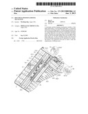
[0036] Please refer to FIGS. 5 and 6 again. The switching module 63 is disposed on the paper input tray 5. Via the switching module 63, the document position-limiting mechanism 6 may be switched from a manual positioning mode to a graduation positioning mode, or switched from the graduation positioning mode to the manual positioning mode. The switching module 63 comprises a driving part 631 and a positioning plate 632. The driving part 631 has a switching button 6311 and a fixing bulge 6312. By moving the switching button 6311, the switching module 63 may be driven. In addition, the switching button 6311 is exposed to the paper input tray 5 (see also FIG. 4). The fixing bulge 6312 is disposed on the inner surface 55 of the paper input tray 5. In this embodiment, the fixing bulge 6312 and the switching button 6311 are integrally formed with the driving part 631.
[0037] The positioning plate 632 is disposed on the inner surface 55 of the paper input tray 5, and located adjacent to the driving part 631. The positioning plate 632 comprises a plurality of recesses 6321, 6322, 6323 and a plurality of sliding grooves 6324. The positioning posts 58 of the paper input tray 5 are penetrated through respective sliding grooves 6324. The sliding grooves 6324 are used for limiting the moving direction of the positioning plate 632. By moving the switching button 6311 in a first direction D1*, the positioning plate 632 is pushed by the driving part 631. Moreover, due to the structures of these sliding grooves 6324, the positioning plate 632 is moved in a second direction D2*. In this embodiment, the sliding grooves 6324 are tilted by 45 degrees with respect to the horizontal line. That is, the sliding grooves 6324 are oriented in the 45-degree direction with respect to the first direction DV and the second direction D2*. Moreover, the first direction DV of moving the switching button 6311 is perpendicular to the third direction D3* of moving the first paper guide plate 60 and the fourth direction D4* of moving the second paper guide plate 61.
[0038] As the first paper guide plate 60 or the positioning plate 632 is moved, the protrusion 6031 of the extension arm 603 may be inserted into one of the recesses 6321, 6322, 6323. Under this circumstance, the document position-limiting mechanism 6 is operated in the graduation positioning mode. As the protrusion 6031 of the extension arm 603 is disengaged from the corresponding one of the recesses 6321, 6322, 6323, the document position-limiting mechanism 6 is operated in the manual positioning mode.
[0039] The operations of the document position-limiting mechanism 6 in the manual positioning mode and the graduation positioning mode will be illustrated in more details as follows. Please refer to FIGS. 5 and 6. In a case that the document position-limiting mechanism 6 is operated in the manual positioning mode, the fixing bulge 6312 of the driving part 631 is inserted into the first positioning notch 56 of the paper input tray 5. In addition, the positioning posts 58 are accommodated within respective sliding grooves 6324 of the positioning plate 632. In this situation, the positioning posts 58 are located at the first ends 6324A of respective sliding grooves 6324.
[0040] When the user wants to scan an A6-sized document, the document position-limiting mechanism 6 should be firstly adjusted to comply with the A6-sized document. The method of adjusting the document position-limiting mechanism 6 comprises the following steps. First of all, the location of the first graduation 51 corresponding to the A6-sized document is realized by the naked eyes. Then, the first paper guide plate 60 is moved toward the location of the first graduation 51 while the first paper guide plate 60 is aligned with the third graduation 51 by naked eyes. Whereas, in response to movement of the first paper guide plate 60, the second paper guide plate 61 is moved to a corresponding location. Then, the A6-sized document is placed on the document position-limiting mechanism 6. Meanwhile, the first edge of the document is stopped by the first paper stopper 601 of the first paper guide plate 60, and the second edge of the document is stopped by the second paper stopper 611 of the second paper guide plate 61. In such way, the document will not be aslant fed into the internal portion of the automatic document feeder. That is, the operations of the document position-limiting mechanism 6 in the manual positioning mode are similar to those of the conventional document position-limiting mechanism 2.
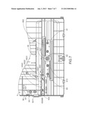
[0041] FIG. 7 is a schematic bottom view illustrating the document position-limiting mechanism according to the embodiment of the present invention, in which the document position-limiting mechanism is operated in a graduation positioning mode. For switching the operating mode of the document position-limiting mechanism 6 to the graduation positioning mode, the switching button 6311 of the driving part 631 may be moved in the first direction D1*. Consequently, the fixing bulge 6312 of the driving part 631 is disengaged from the first positioning notch 56 and then inserted into the second positioning notch 57. As the switching button 6311 is moved in the first direction D1*, the positioning plate 632 is pushed by the driving part 631, so that the positioning plate 632 is moved in the second direction D2*. In response to movement of the positioning plate 632, the recesses 6321, 6322, 6323 of the positioning plate 632 are closer to the first paper guide plate 60. In addition, the positioning posts 58 are located at the second ends 6324B of respective sliding grooves 6324. Under this circumstance, the document position-limiting mechanism is operated in the graduation positioning mode (see FIG. 7).
[0042] When the user wants to scan an A6-sized document, the document position-limiting mechanism 6 should be firstly adjusted to comply with the A6-sized document. Then, the first paper guide plate 60 is moved toward the location of the first graduation 51 corresponding to the A6-sized document. Once the first paper guide plate 60 reaches the location of the first graduation 51, the protrusion 6031 of the extension arm 603 is inserted into the first recess 6321 corresponding to the first graduation 51. During the protrusion 6031 is inserted into the first recess 6321, a tactile feel is clearly sensed by the user. According to the tactile feel, the user may assure that the first paper guide plate 60 and the second paper guide plate 61 are located at the positions corresponding to the A6-sized document without the need of using the naked eyes to align the graduation. That is, the operations of the document position-limiting mechanism 6 in the graduation positioning mode are similar to those of the conventional document position-limiting mechanism 4.
[0043] From the above description, the document position-limiting mechanism has a switching module. Via the switching module, the operating mode of the document position-limiting mechanism can be switched. In a case that the document position-limiting mechanism is operated in the graduation positioning mode, the first paper guide plate may be aligned with the graduation without using the naked eyes. Whereas, in a case that the document position-limiting mechanism is operated in the manual positioning mode, the first paper guide plate and the second paper guide plate may be arbitrarily moved to any locations, so that various sizes of documents may be placed on the position-limiting mechanism. Consequently, according to the practical requirements of different users, the document position-limiting mechanism of the present invention can be applied to various sizes of documents or can be easily used to align the first paper guide plate without using the naked eyes.
[0044] While the invention has been described in terms of what is presently considered to be the most practical and preferred embodiments, it is to be understood that the invention needs not be limited to the disclosed embodiment. On the contrary, it is intended to cover various modifications and similar arrangements included within the spirit and scope of the appended claims which are to be accorded with the broadest interpretation so as to encompass all such modifications and similar structures.
User Contributions:
Comment about this patent or add new information about this topic:
Images included with this patent application:
 |  |
 |  |
 |  |
 |  |
| Similar patent applications: | |
| Date | Title |
|---|---|
| 2008-08-21 | Coupling mechanism |
| 2008-08-28 | System and method for document tagging templates |
| 2008-08-21 | Adjustment mechanism |
| 2008-08-21 | Optimized document printing |
| 2008-08-21 | Height adjustment mechanism |
| New patent applications in this class: | |
| Date | Title |
|---|---|
| 2016-07-14 | Sheet storage apparatus and image forming apparatus |
| 2016-06-30 | Stacking device and image forming apparatus |
| 2016-05-26 | Sheet feeding cassette and image forming apparatus including this |
| 2016-05-26 | Sheet cassette, feeder, and image forming apparatus |
| 2016-05-19 | Paper tray size sensing mechanism |
| New patent applications from these inventors: | |
| Date | Title |
|---|---|
| 2013-12-05 | Light guide casing |
| 2013-11-21 | Duplex scanning apparatus and sheet-feeding control method thereof |
| 2013-05-23 | Sheet sensing module and duplex scanning apparatus using the same |
| 2013-03-07 | Document position-limiting mechanism |
| 2012-06-21 | Automatic document feeder |
| Top Inventors for class "Sheet feeding or delivering" | |
| Rank | Inventor's name |
|---|---|
| 1 | Tetsuo Asada |
| 2 | Lloyd A. Williams |
| 3 | Canon Kabushiki Kaisha |
| 4 | Mizuna Tanaka |
| 5 | Yuji Koga |