Patent application title: MOBILE POOL SKIMMER
Inventors:
Scott Veronie (Houma, LA, US)
IPC8 Class: AE04H416FI
USPC Class:
2101672
Class name: For swimming pool or spa (e.g., skimmer, etc.) mesh or screen filter at or near water surface having floating means
Publication date: 2012-12-06
Patent application number: 20120305461
Abstract:
A mobile skimmer that can be propelled by either human manipulation or
wind power to capture debris floating on or near the surface of a body of
liquid, and more particularly, a swimming pool. It further comprises a
unique netted trap design to trap and retain debris even while floating
freely in the water. A hinged buoyant flap has one end positioned below
the surface of the water, with another end that moves above and below the
surface depending on the movement of the skimmer, thereby collecting and
trapping debris. A sail may be used to move the skimmer.Claims:
1. A mobile floating pool skimmer for collecting debris on or below the
surface of the water, comprising: two parallel pontoons, each with
corresponding first ends and second ends; a first buoyant flap extending
between the corresponding first ends of the pontoons, said first buoyant
flap comprising a top edge and a bottom edge, wherein the bottom edge is
positioned below the surface of the water and the top edge moves between
a position above the surface of the water and a position below the
surface of the water; and a first netted trap positioned between the
pontoons, said first netted trap comprising a first end, a second end,
and two sides, wherein the first end is fastened to the top edge of the
first buoyant flap; wherein the top edge of the first buoyant flap moves
to the position below the surface of the water when the skimmer is
propelled in the direction of the first ends of the pontoons to permit
collection of the debris, and moves to the position above the surface of
the water when not so propelled so as to retain the debris in the first
netted trap.
2. The skimmer of claim 1, further comprising a first submerged beam extending across the corresponding first ends of the pontoons, wherein the bottom edge of the first buoyant flap is hingedly connected to the first submerged beam.
3. The skimmer of claim 1, wherein the first submerged beam is positioned to create an upward surge or wave of water when the skimmer is propelled in the direction of the first ends of the pontoons.
4. The skimmer of claim 1, further comprising a first cross beam extending across the corresponding first ends of the pontoons above the surface of the water.
5. The skimmer of claim 4, further comprising a second cross beam extending across the corresponding second ends of the pontoons above the surface of the water.
6. The skimmer of claim 5, further comprising a third cross beam extending across the corresponding centers of the pontoons above the surface of the water.
7. The skimmer of claim 4, further comprising a latch or rod on the first cross beam, wherein the latch or rod is adapted to connect with a latch tool.
8. The skimmer of claim 7, wherein the latch or rod comprises a stem with a ball at the top.
9. The skimmer of claim 8, wherein the underside of the ball comprises a flat angled section where it meets the stem.
10. The skimmer of claim 9, wherein the angle is approximately 45 degrees.
11. The skimmer of claim 10, wherein the flat angled section corresponds to a matching flat angled section inside the latch tool.
12. The skimmer of claim 11, wherein the latch tool is attached to a pole.
13. The skimmer of claim 12, wherein the skimmer is manually pushed.
14. The skimmer of claim 13, wherein the weight of the pole is borne by the skimmer.
15. The skimmer of claim 1, further comprising a sail positioned on the skimmer above the surface of the water.
16. The skimmer of claim 15, wherein the skimmer is moved by wind power.
17. The skimmer of claim 1, further comprising a second buoyant flap extending between the corresponding second ends of the pontoons, said second buoyant flap comprising a top edge and a bottom edge, wherein the bottom edge is positioned below the surface of the water and the top edge moves between a position above the surface of the water and a position below the surface of the water; wherein the top edge of the first buoyant flap moves to the position below the surface of the water and the top edge of the second buoyant flap moves to the position above the surface of the water when the skimmer is propelled in the direction of the first ends of the pontoons; and the top edge of the first buoyant flap moves to the position above the surface of the water and the top edge of the second buoyant flap moves to the position below the surface of the water when the skimmer is propelled in the direction of the second ends of the pontoons.
18. The skimmer of claim 17, wherein the top of the second buoyant flap is attached to the second end of the first netted trap.
19. The skimmer of claim 17, further comprising a second netted trap, wherein the top of the second buoyant flap is attached to one end of the second netted trap.
20. The skimmer of claim 1, wherein the pontoons are hydrodynamically shaped.
Description:
[0001] This application claims benefit of and priority to U.S. Provisional
Application No. 61/520,148, filed Jun. 6, 2011 by Scott Veronie, and U.S.
Provisional Application No. 61/571,359, filed Jun. 27, 2011 by Scott
Veronie, and is entitled to those filing dates for priority in whole or
in part. The specification, figures and complete disclosure of U.S.
Provisional Applications Nos. 61/520,148 and 61/571,359 are incorporated
herein by specific reference for all purposes.
FIELD OF INVENTION
[0002] This invention relates to a device for removing and cleaning debris from the surface of a body of liquid. More particularly, this invention relates to mobile device for removing and cleaning debris from the surface of a swimming pool or similar body of water.
BACKGROUND OF THE INVENTION
[0003] There are numerous devices and methods disclosed in the prior that attempt to solve the problem of removing or skimming leaves and other debris at or near the surface of water in a swimming pool. These include filters and skimmers associated with a pump circulating pool water, as well as more simple devices such as a net positioned at the end of a pole. Examples of such devices and methods are disclosed in U.S. Pat. Nos. 4,176,419; 4,472,842; 4,518,495; 4,820,411; 4,822,487; 5,043,060; 5,422,001; 5,614,085; 5,705,058; 5,849,184; 5,911,878; 5,951,858; 6,132,604; 6,358,410; 6,383,374; 7,033,490; and 7,037,038; all of which are incorporated herein by specific reference for all purposes.
[0004] Despite the number of such devices, however, a number of problems remain. Automatic mounted skimmers are only operational while the pool pump is on, require an external power source, and usually are not efficient enough to clean a pool thoroughly. These typically are supplemented with manual skimmers, but manipulating a pole attached to a net or skimmer often results in operator fatigue and muscle and back strain. Manual skimmers also often have to be removed several times during the cleaning process to remove the debris, which is labor intensive and time consuming.
SUMMARY OF INVENTION
[0005] In various embodiments, the present invention comprises a mobile skimmer that can be propelled by either human manipulation or wind power to capture debris floating on or near the surface of a body of liquid, and more particularly, a swimming pool. It further comprises a unique netted trap design to trap and retain debris even while floating freely in the water.
[0006] In one embodiment, the skimmer floats atop the water on two buoyant pontoons. Each pontoon has a front and a back. In one particular embodiment, the front of a pontoon is angled, curved or shaped like the prow of a boat. The back of each pontoon may be square or rounded, but also may have a similar shape to the front. Other shapes for the front and back may be used. The underside of each pontoon also may have a keel protruding down into the water. In the embodiment shown, the keel is located proximate to the back or second end of the pontoon, although it may be positioned elsewhere. Multiple keels on a pontoon may be used.
[0007] The pontoons are connected by at least one cross-piece or cross-beam. In one embodiment, the pontoons are connected by a front cross beam and a rear cross beam. The front cross beam is positioned above the water surface during use. Submerged rods extend downward into the water from the underside of the front of the pontoons or the front cross beam. A submerged beam may extend between the respective submerged rods. A buoyant flap is hingedly attached to the submerged rods or the submerged beam at one end, with the point of attachment being below the surface of the water.
[0008] When not being propelled, the end of the buoyant flap opposite the hinge protrudes above the surface of the water. When being propelled forward, the flow of water causes the buoyant flap to submerge entirely. Floating debris (such as leaves) enters the skimming by moving under the front cross beam and over the buoyant flap. The debris enters a netted trap where it is collected and held. The water surge created by the submerged beam and the buoyant flap also helps in debris collection (i.e., it creates an upsurge or wave that raises the water's surface over the top of the buoyant flap).
[0009] The netted trap comprises a fine mesh or netting that is secured (removably or permanently) on both sides to the respective pontoons and at the back to the rear cross beam. Alternatively, it may be secured to a netted trap frame, which is attached (removably or permanently) to the pontoons and rear cross beam. The front of the mesh or netting may be attached to the buoyant flap at or near the free end of the buoyant flap as shown, or elsewhere. In one embodiment, the mesh or netting is attached to the buoyant flap by a plate. When propulsion ceases, the buoyant flap pivots upward so the free end rises to a partially surfaced position, thereby preventing the debris from leaving the trap. Movement in the opposite direction creates no downward force on the flap, and in fact creates a lifting force
[0010] The skimmer may be propelled by a variety of mechanisms, including but not limited to manual (human) and wind. A person in the water may simply move the skimmer about by hand to collect debris. Handles may be placed on the pontoons or cross beams in suitable locations for ease of use.
[0011] Alternatively, in one embodiment, a rod or latch extends upward from the front of the skimmer, either from a pontoon or the front cross beam. In the embodiment shown, the latch is positioned at or near the center of the front cross beam. A latch tool positioned at the end of a pole (which may be telescoping) is placed over the latch, and is manipulated by the user around the pool while standing outside the water. The positions of the latch tool and latch may be reversed (i.e., the rod or latch may be located on the end of the pole, and fit within a receiving latch tool or hole in the skimmer).
[0012] In use, the weight of the pole is borne by the skimmer, thereby reducing or eliminating the stress and fatigue of the user. The user may, in fact, be able to manipulate the device with a single hand. The weight of the pole also caused the skimmer to tilt to the front when in use, thereby assisting in debris collection. In addition, where the pontoons have a similar shape to the pontoons on a boat or catamaran, water drag is minimized, allowing faster maneuvering and easier propulsion with less effort.
[0013] In one embodiment, the latch comprises a stem with a bulbous or semi-spherical top. The underside of the top is joined to the stem by a flat angled section. In the embodiment shown, the flat angled section is approximately 45 degrees in relation to the longitudinal direction of the stem. The latch tool comprises a pole connection at one end that allows the latch tool to pivot or rotate in multiple directions. In one embodiment, the connection allows for 360 degree rotation similar to a ball joint connection, and has a minimal turning radius for easy and efficient operation.
[0014] The latch tool further comprises an opening at the opposite end of sufficient size to receive the top of the latch. The interior of the latch tool narrows inward to a lip. At the narrowest point at the lip, the opening is only slightly larger than the top of the latch. The innermost part of the lip forms a flat angled section to correspond to the flat angled section of the latch. This allows the pole to be used to manipulate the skimmer without becoming easily disconnected, but still allowing the pole to be detached when desired. In this configuration, the latch tool is easily latched or unlatched with a predominantly vertical movement, but remains latched under predominantly horizontal movement even with a significant vertical component due to the interaction of the flat angled sections. This permits the user to lift the skimmer out of the pool with a predominantly horizontal force, and then unlatch the pole by employing a predominantly vertical force.
[0015] In yet another embodiment, one or more sails are mounted on top of the pontoons so the skimmer acts as a free-floating wind-propelled skimmer. The skimmer can be left in the pool, and collects debris as it is propelled around the pool by the wind. Collection may be assisted by a forward tilt of the skimmer caused by the propulsion. The sails may be hingedly or pivotally attached, allowing for some movement from side to side. Lines may be attached to the sail to hold the sail within a limited range of movement. In one embodiment, the sail is allowed approximately 8 to 12 degrees of movement from the vertical (this configuration is particularly useful with a double-ended skimmer, as described below). The sail or sails may be detachable or interchangeable, thereby allowing sails with a variety of colors, message, graphics or images to be used. In a pool at a hotel or other business, for example, the sails can be used to advertise, display logos, or the like.
[0016] Other means of propulsion can be used. For example, a motor-driven propeller may be attached to the back end of the skimmer. The motor may be powered by batteries, solar power, or some similar source. In one embodiment, a solar panel is located on the skimmer to receive and store solar energy. The solar panel may take the place of the sail, or even act, in whole or in part, as a sail.
[0017] In another embodiment, the skimmer may be double-ended. A center cross bar extends across the middle of the skimmer, with two end cross bars at either end. Each of these ends comprises a buoyant flap, submerged beam, netted trap and other components as described above. Two netted traps may be used, although a single netted trap in the center may be used. Thus, while the skimmer is moved or blown in one direction, debris is collected in the forward end relative to the movement, while debris is retained at the back end or in the second trap in the rear.
[0018] A variety of materials may be used, including wood, plastic, foam, cloth or metal. Materials should be resistant to the effects of swimming pool environments, such as rust, salt water, chlorine, UV rays, and the like. The pontoons may be solid or hollow. In one embodiment, the pontoons are inflatable.
[0019] Offset rods may extend outward from one or more ends of the pontoons. These help the skimmer turn when a wall or side of the pool is struck, and also help to direct debris towards the netted trap. In yet another embodiment, brushes may be located on the outside of the pontoons or keels. These may serve as bumpers or buffers when the skimmer contacts the sides of the pool, and also may assist in cleaning the tiles or sides of the pool when contacted.
BRIEF DESCRIPTION OF THE DRAWINGS
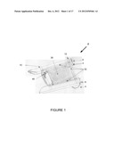
[0020] FIG. 1 shows a top perspective view of a skimmer in accordance with an embodiment of the present invention.
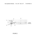
[0021] FIG. 2 shows a partial side view of a netted trap and buoyant flap design in accordance with an embodiment of the present invention.
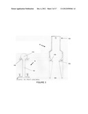
[0022] FIG. 3 shows a side view of an exemplary embodiment of a latch and latch tool.
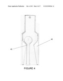
[0023] FIG. 4 shows a cutaway side view of a latch inserted into the latch tool.
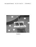
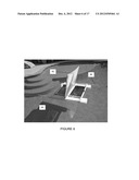
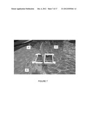
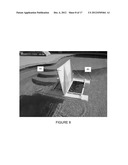
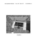
[0024] FIGS. 5-8 show side perspective views of a double-ended skimmer with a sail in accordance with an embodiment of the present invention.
[0025] FIG. 9 shows an end perspective view of the skimmer of FIGS. 5-8.
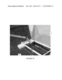
[0026] FIG. 10 shows the latch tool being inserted over the latch.
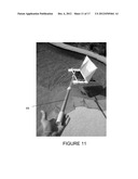
[0027] FIG. 11 shows the skimmer in use with a pole and sail.
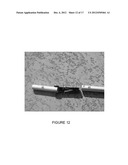
[0028] FIG. 12 shows a latch tool and pole connector.
[0029] FIGS. 13 and 14 show perspective views of alternative embodiments of a skimmer.
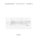
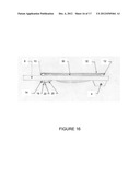
[0030] FIGS. 15 and 16 show side profiles of the netted trap design (left pontoon removed and in place).
[0031] FIG. 17 shows a perspective view of an alternative embodiment of a skimmer with a sail.
DETAILED DESCRIPTION OF EXEMPLARY EMBODIMENTS
[0032] In various exemplary embodiments, the present invention comprises a mobile skimmer that can be propelled by either human manipulation or wind power to capture debris floating on or near the surface of a body of liquid, and more particularly, a swimming pool. It further comprises a unique netted trap design to trap and retain debris even while floating freely in the water. The skimmer and its components may be of varying sizes as appropriate for the environment in which it is used.
[0033] As shown in FIG. 1, the skimmer 2 floats atop the water on two buoyant pontoons (right 6 and left 8). Each pontoon has a front and a back (or a first end and second end). In one particular embodiment, the front or first end of a pontoon is angled, curved or shaped like the prow of a boat. The pontoons may be hydronamically shaped in length and cross-section, similar to the pontoons in a boat or catamaran. The back of each pontoon may be square or rounded, but also may have a similar shape to the front. Other shapes for the front and back may be used. The underside of each pontoon also may have a keel 4 protruding down into the water. In the embodiment shown, the keel is located proximate to the back or second end of the pontoon, although it may be positioned elsewhere. Multiple keels on a pontoon may be used.
[0034] The pontoons are connected by at least one cross-piece or cross-beam. In the embodiment shown in FIG. 1, the pontoons are connected by a front cross beam 10 and a rear cross beam 12. The front cross beam is positioned above the water surface during use. Submerged rods 14 extend downward into the water from the underside of the front of the pontoons or the front cross beam. A submerged beam 16 may extend between the respective submerged rods. A buoyant flap 20 is hingedly attached 22 (by one or more hinges) to the submerged rods or the submerged beam at one end, with the point of attachment being below the surface of the water.
[0035] When not being propelled, the end of the buoyant flap opposite the hinge protrudes above the surface of the water. When being propelled forward, the flow of water causes the buoyant flap to submerge entirely. Floating debris (such as leaves) enters the skimming by moving under the front cross beam 10 and over the buoyant flap. The debris enters a netted trap 30 where it is collected and held. The water surge created by the submerged beam and the buoyant flap also helps in debris collection (i.e., it creates an upsurge or wave that raises the water's surface over the top of the buoyant flap).
[0036] The netted trap comprises a fine mesh or netting that is secured (removably or permanently) on both sides to the respective pontoons and at the back to the rear cross beam. Alternatively, it may be secured to a netted trap frame 32, which is attached (removably or permanently) to the pontoons and rear cross beam. The front of the mesh or netting may be attached to the buoyant flap at or near the free end of the buoyant flap as shown, or elsewhere. In one embodiment, the mesh or netting is attached to the buoyant flap by a plate 36. When propulsion ceases, the buoyant flap pivots upward so the free end rises to a partially surfaced position, thereby preventing the debris from leaving the trap. Movement in the opposite direction creates no downward force on the flap, and in fact creates a lifting force.
[0037] The skimmer may be propelled by a variety of mechanisms, including but not limited to manual (human) and wind. A person in the water may simply move the skimmer about by hand to collect debris. Handles may be placed on the pontoons or cross beams in suitable locations for ease of use.
[0038] Alternatively, in one embodiment, a rod or latch 40 extends upward from the front of the skimmer, either from a pontoon or the front cross beam. In the embodiment shown, the latch 40 is positioned at or near the center of the front cross beam. A latch tool 42 positioned at the end of a pole (which may be telescoping) 44 is placed over the latch, and is manipulated by the user around the pool while standing outside the water, as seen in FIGS. 10 through 12. The positions of the latch tool and latch may be reversed (i.e., the rod or latch may be located on the end of the pole, and fit within a receiving latch tool or hole in the skimmer).
[0039] In use, the weight of the pole is borne by the skimmer, thereby reducing or eliminating the stress and fatigue of the user. The user may, in fact, be able to manipulate the device with a single hand. The weight of the pole also caused the skimmer to tilt to the front when in use, thereby assisting in debris collection. In addition, where the pontoons have a similar shape to the pontoons on a boat or catamaran, water drag is minimized, allowing faster maneuvering and easier propulsion with less effort.
[0040] In one embodiment, as seen in FIGS. 3 and 4, the latch 40 comprises a stem 142 with a bulbous or semi-spherical top 144. The underside of the top is joined to the stem by a flat angled section 146. In the embodiment shown, the flat angled section is approximately 45 degrees in relation to the longitudinal direction of the stem. The latch tool 42 comprises a pole connection 152 at one end that allows the latch tool to pivot or rotate in multiple directions.
[0041] The latch tool further comprises an opening 154 at the opposite end of sufficient size to receive the top of the latch. The interior of the latch tool narrows inward to a lip 156. At the narrowest point at the lip, the opening is only slightly larger than the top of the latch. The innermost part of the lip forms a flat angled section 158 to correspond to the flat angled section 146 of the latch. This allows the pole to be used to manipulate the skimmer without becoming easily disconnected, but still allowing the pole to be detached when desired. In this configuration, the latch tool is easily latched or unlatched with a predominantly vertical movement, but remains latched under predominantly horizontal movement even with a significant vertical component due to the interaction of the flat angled sections 146, 158. This permits the user to lift the skimmer out of the pool with a predominantly horizontal force, and then unlatch the pole by employing a predominantly vertical force. In use, the latch-latch tool connection allows for 360 degree rotation similar to a ball joint connection, and has a minimal turning radius for easy and efficient operation.
[0042] In yet another embodiment, one or more sails 50 are mounted on top of the pontoons so the skimmer acts as a free-floating wind-propelled skimmer. The skimmer can be left in the pool, and collects debris as it is propelled around the pool by the wind. Collection may be assisted by a forward tilt of the skimmer caused by the propulsion. The sails may be hingedly or pivotally attached, allowing for some movement from side to side. Lines may be attached to the sail to hold the sail within a limited range of movement. In one embodiment, the sail is allowed approximately 8 to 12 degrees of movement from the vertical (this configuration is particularly useful with a double-ended skimmer, as described below). The sail or sails may be detachable or interchangeable, thereby allowing sails with a variety of colors, message, graphics or images to be used. In a pool at a hotel or other business, for example, the sails can be used to advertise, display logos, or the like.
[0043] Other means of propulsion can be used. For example, a motor-driven propeller may be attached to the back end of the skimmer. The motor may be powered by batteries, solar power, or some similar source. In one embodiment, a solar panel is located on the skimmer to receive and store solar energy. The solar panel may take the place of the sail, or even act, in whole or in part, as a sail.
[0044] In another embodiment, the skimmer may be double-ended. As seen in FIGS. 5-9, a center cross bar 70 extends across the middle of the skimmer, with two end cross bars 72, 74 at either end. Each of these ends comprises a buoyant flap, submerged beam, netted trap and other components as described above. Two netted traps may be used, although a single netted trap in the center may be used. Thus, while the skimmer is moved or blown in one direction, debris is collected in the forward end relative to the movement, while debris is retained at the back end or in the second trap in the rear.
[0045] A variety of materials may be used, including wood, plastic, foam, cloth or metal. Materials should be resistant to the effects of swimming pool environments, such as rust, salt water, chlorine, UV rays, and the like. The pontoons may be solid or hollow. In one embodiment, the pontoons are inflatable.
[0046] As seen in FIGS. 5-9, offset rods 60 may extend outward from one or more ends of the pontoons. These help the skimmer turn when a wall or side of the pool is struck, and also help to direct debris towards the netted trap. In yet another embodiment, brushes may be located on the outside of the pontoons or keels. These may serve as bumpers or buffers when the skimmer contacts the sides of the pool, and also may assist in cleaning the tiles or sides of the pool when contacted.
[0047] Thus, it should be understood that the embodiments and examples described herein have been chosen and described in order to best illustrate the principles of the invention and its practical applications to thereby enable one of ordinary skill in the art to best utilize the invention in various embodiments and with various modifications as are suited for particular uses contemplated. Even though specific embodiments of this invention have been described, they are not to be taken as exhaustive. There are several variations that will be apparent to those skilled in the art.
User Contributions:
Comment about this patent or add new information about this topic:
Images included with this patent application:
 |  |
 |  |
 |  |
 |  |
 |  |
 |  |
 |  |
| Similar patent applications: | |
| Date | Title |
|---|---|
| 2009-06-18 | Remote control pool skimmer |
| 2013-07-25 | Swimming pool skimmer leaf restraint |
| 2013-10-03 | Net assembly for pool skimmer |
| 2012-04-12 | Automatic tilting oil skimmer frame |
| 2013-02-21 | Whirlpool skimmer |
| New patent applications in this class: | |
| Date | Title |
|---|---|
| 2010-09-16 | Surface skimming device for pools |
| 2009-07-30 | Stationary pool skimming apparatus |
| Top Inventors for class "Liquid purification or separation" | |
| Rank | Inventor's name |
|---|---|
| 1 | Robert W. Childers |
| 2 | Joseph A. King |
| 3 | John R. Hacker |
| 4 | Martin T. Gerber |
| 5 | Rodolfo Roger |