Patent application title: Method And System For Aiding The Piloting Of An Airplane During An Approach
Inventors:
Stephane Puig (Lauzerville, FR)
Stephane Puig (Lauzerville, FR)
Stéphane Puig (Lauzerville, FR)
Martin Delporte (Fonsorbes, FR)
Jerome Gauvain (Toulouse, FR)
Jérôme Gauvain (Toulouse, FR)
Assignees:
AIRBUS OPERATIONS (SAS)
IPC8 Class: AG05D104FI
USPC Class:
701 18
Class name: Aeronautical vehicle with indication or control of landing profile of descent
Publication date: 2012-11-29
Patent application number: 20120303186
Abstract:
The system (1) comprises means (5) for calculating a limit roll angle and
a display (7) for automatically presenting on a screen (10) a first
characteristic sign illustrating the current value of the roll angle and
a second characteristic sign illustrating said limit roll angle allowing
to check that an end point of the aircraft does not come into contact
with the ground.Claims:
1. An aiding method for the piloting of an airplane upon an approach
phase to an airport, wherein the following succession of steps is carried
out on an automatic and repetitive way, consisting in: a) determining the
current values of a height of an airplane (AC) relative to the ground and
a pitch angle of said airplane (AC); b) from such current values and
geometrical data being representative of said airplane (AC) and related
to an end point (P1, P2) of the airplane (AC), calculating a limit roll
angle, which is a maximum roll angle up to the value for which it is
guaranteed that said end point (P1, P2) of the airplane (AC) will not
strike the ground, said limit roll angle φlim being calculated
by means of the following expressions: cos.sup.2.phi.lim=(-b+
{square root over (b2-4ac)})/2a with:
a=Y.sub.1.sup.2+(HRA+Z2-Z1)2
b=2tgθ(HRA+Z2-Z1)X1
c=tg.sup.2.theta.X.sub.1.sup.2-Y.sub.1.sup.2 wherein: tg represents the
tangent: θ is the pitch angle of the airplane (AC); HRA is the
height of the airplane (AC) relative to the ground, being measured by a
radio-altimeter according to a measurement direction; Z2 is the
distance along said measurement direction between the centre of gravity
of the airplane (AC) and the measurement point of the radio-altimeter;
and X1, Y1 and Z1 are geometrical data being
representative of said airplane (AC) and correspond to the distances
between the centre of gravity and said end point, respectively along the
three axes of a fix bound to the airplane (AC); c) determining the
current value of the roll angle of the airplane (AC); and d) presenting
on a same screen a first characteristic sign (12) illustrating said
current value of the roll angle and a second characteristic sign (11)
illustrating said limit roll angle.
2. The method according to claim 1, wherein, in a further step, automatically and repetitively, said current value of the roll angle is compared to the sum of said limit roll angle and a predetermined angle, and an alarm message is emitted if said current value of the roll angle is higher than said sum.
3. The method according to claim 1, wherein, in a further step, automatically and repetitively, said current value of the roll angle is compared to the sum of said limit roll angle and a predetermined margin, and, if said current value of the roll angle is higher than said sum, the airplane (AC) is automatically controlled so that the current value of the roll angle become lower than or equal to said sum.
4. The method according to claim 1, wherein: at step b), an estimation of a future value of the roll angle of the airplane (AC) is in addition carried out; and at step d), a third characteristic sign (21) illustrating said future value of the roll angle is additionally presented on said screen (10).
5. The method according to claim 4, wherein, at step b), said future value of the roll angle is calculated from the derivative of the current value of the roll angle of the airplane (AC) and a predetermined prediction time.
6. The method according to claim 1, wherein, upon the approach, the current value of the height of the airplane (AC) is automatically and repetitively determined relative to the ground, such current value is compared to a predetermined height value, and said steps b) to d) are implemented, as soon as said current height becomes lower than said predetermined height value.
7. The method according to claim 1, applied to an airplane (AC) provided with engines (M) arranged under the wings (W), wherein two following end points are taken into account: one wing (W) tip (P1) and one engine (M) pod end (P2), and said steps b) and d) are implemented for both end points, and then the most penalizing value is kept as a function of current flight parameters of the airplane (AC).
8. An automatic aiding system for the piloting of an airplane upon an approach phase to an airport, said system (1) comprising: a set (2) of information sources to automatically determine the current values of an airplane (AC) height relative to the ground and of a pitch angle of the airplane (AC); means (5) for automatically calculating, from such current values and geometrical data being representative of said airplane (AC) and related to an end point (P1, P2) of the latter, a limit roll angle, which is a maximum roll angle up to the value for which it is guaranteed that said end point (P1, P2) of the airplane (AC) will not strike the ground, said limit roll angle φlim being calculated by means of the following expressions: cos.sup.2.phi.lim=(-b+ {square root over (b2-4ac)})/2a with: a=Y.sub.1.sup.2+(HRA+Z2-Z1)2 b=2tgθ(HRA+Z2-Z1)X1 c=tg.sup.2.theta.X.sub.1.sup.2-Y.sub.1.sup.2 wherein: tg represents the tangent: θ is the pitch angle of the airplane (AC); HRA is the height of the airplane (AC) relative to the ground, being measured by a radio-altimeter according to a measurement direction; Z2 is the distance along said measurement direction between the centre of gravity of the airplane (AC) and the measurement point of the radio-altimeter; and X1, Y1 and Z1 are geometrical data being representative of said airplane (AC) and correspond to the distances between the centre of gravity and said end point, respectively along the three axes of a fix bound to the airplane (AC); means (6) for automatically determining the current value of the airplane (AC) roll angle; and a display (7), which is able to automatically present, on a same screen (10), a first characteristic sign (12) illustrating said current value of the roll angle and a second characteristic sign (11) illustrating said limit roll angle.
9. The system according to claim 8, wherein said screen (10) is a primary flight screen.
10. The system according to claim 8, wherein said set (2) of information sources comprises at least one radio-altimeter to determine the current value of the airplane (AC) height relative to the ground.
11. The system according to claim 8, wherein it comprises additionally means (14) to automatically compare said current value of the roll angle to the sum of said limit roll angle and a predetermined margin, and alarm means (16) to automatically emit an alarm message if said current value of the roll angle is higher than the latter sum.
12. The system according to claim 8, wherein it comprises additionally means (14) to automatically compare said current value of the roll angle to the sum of said limit roll angle and a predetermined margin, and means (18) to automatically control the airplane (AC) if said current value of the roll angle is higher than said sum, so as to bring the current value of the roll angle back to a value being lower than or equal to said sum.
13. An airplane, wherein it comprises a system (1) such as the one specified in claim 8.
Description:
[0001] The present invention relates to a method and system for aiding the
piloting of an airplane upon an approach to an airport with a view to a
landing, in particular upon a flare phase.
[0002] In the framework of the present invention, the term flare phase means a righting phase for an airplane generally preceding a landing. It is known that risks of coming into contact with the ground with a part of the canopy or a part of the engines can exist upon such phase.
[0003] During the flare phase, the pilot must focus on the attitude angles of the airplane, namely the attitude, the roll and the heading. He must also focus on keeping the airplane in the axis of the runway and limiting the load applied to the airplane upon the contact with the ground.
[0004] When the airplane is close to the ground, it may meet blustering wind and the direction thereof may change. The crew must be conscious that, upon the approach phase, and specifically upon the flare phase, side wind may suddenly change the attitude and the roll, thereby resulting in a tail strike, but also a sideslip. Such events may also lead to roll variations, side deviations, and then potentially canopy strikes and/or turn-offs. Side wind may moreover generate a turn-off, which leads to a roll angle being modified in an aerodynamic way.
[0005] The main effects of a ground strike are degradations of canopy edges and engines, with possibly effects on the airplane safety.
[0006] A canopy strike may sometimes be the consequence of too a large roll compensation realized so as to avoid a turn-off. The pilot should thus find the better compromise between the side deviations, the airplane control and the strikes of airplane members with the ground, which represents a large work load.
[0007] An object of the present invention aims at remedy the above mentioned disadvantages. It relates to a method for aiding the piloting of an airplane, in particular upon a flare phase, which allows to detect (in real time) aboard the plane a risk of collision of canopy members with the ground.
[0008] With this end in view, according to the invention, said method is remarkable in that the following succession of steps is carried out on an automatic and repetitive way, consisting in:
[0009] a) determining the current values of an airplane height relative to the ground and a pitch angle of said airplane;
[0010] b) from such current values and geometrical data being representative of said airplane and related to an end point of the latter, calculating a limit roll angle, which is a maximum roll angle up to the value for which it is guaranteed that said end point of the airplane will not strike the ground;
[0011] c) determining the current value of the roll angle of the airplane; and
[0012] d) presenting on a same display a first characteristic sign illustrating said current value of the roll angle and a second characteristic sign illustrating said limit roll angle.
[0013] Thus, thanks to the invention, it is possible to establish at any time upon the approach (more precisely upon the final phase of the approach and the landing, as detailed hereinunder) the roll limit due to the geometry of the airplane and the current situation (height, pitch) of the airplane, i.e. the limit roll angle that the airplane can reach with no particular end point of the canopy (wing, engine) coming into contact with the ground. Moreover, such value is displayed on a screen in the cockpit of the airplane, together with the current value of the roll angle, allowing the pilot to have an exact representation of the possible risk of a ground strike (by comparing these two characteristic signs).
[0014] The present invention also enables in such a way to increase safety upon an approach.
[0015] In a preferred embodiment, at step b), said limit roll angle φlim is calculated by means of the following expressions:
cos2φlim=(-b+ {square root over (b2-4ac)})/2a
with:
a=Y12+(HRA+Z2-Z1)2
b=2tgθ(HRA+Z2-Z1)X1
c=tg2θX12-Y12
wherein:
[0016] tg represents the tangent:
[0017] θ is the pitching angle of the airplane;
[0018] HRA is the airplane height relative to the ground, being measured by a radio-altimeter along a measurement direction;
[0019] Z2 is the distance along said measurement direction between the centre of gravity of the airplane and the measurement point of the altimeter; and
[0020] X1, Y1 and Z1 are geometrical data being representative of said airplane and correspond to the distances between the centre of gravity and said end point, respectively along the three (rotational) axes of a fix bound to the airplane.
[0021] Furthermore, advantageously, in a further step, said current value of the roll angle is automatically compared to the sum of said limit roll angle and a predetermined margin. In such a case, if said current value of the roll angle is higher than said sum; [0022] in a first embodiment, an alarm message (sound and/or visual) is emitted, allowing the pilot to warn about the situation of striking the ground; and [0023] in a second embodiment (alternatively or additionally), the airplane is automatically controlled so that the current value of the roll angle becomes again lower than or equal to said sum. Such automatic control relieves the pilot of any action to come back in a roll secure position.
[0024] Moreover, in a particular embodiment: [0025] at step b), an estimation of a future value of the roll angle of the airplane is in addition carried out; and [0026] at step d), a third characteristic sign illustrating said future value of the roll angle is additionally presented on said screen.
[0027] Preferably, at step b), said future value of the roll angle is calculated from the derivative of the current value of the roll angle of the airplane and a predetermined prediction time.
[0028] It is also possible to use such estimation of a future value on the roll angle of the airplane to automatically detect an excessive roll future situation, and in such a situation to detect an alarm signal and/or an automatic control, such as the ones above mentioned.
[0029] Moreover, advantageously, upon the approach, the current value of the airplane height is automatically and repetitively determined relative to the ground, such current value is compared to a predetermined height value, and said steps b) to d) are implemented, as soon as said current height becomes lower than said predetermined height value, for example 40 metres.
[0030] The present invention is applied to an end point corresponding to the airplane point being able to first strike the ground upon an excessive roll. Such an end point can be a wing tip or an engine pod end. However, in a preferred embodiment applied for an airplane provided with engines arranged under the wings thereof, advantageously, two following end points are taken into account: one wing tip and one engine pod end, and said steps b) and d) are implemented for both end points, and then the most penalizing value is kept, and this, as a function of current flight parameters (attitude and roll) of the airplane.
[0031] The present invention also relates to an aiding system for the piloting of an airplane upon an approach, in particular upon a flare phase.
[0032] According to the invention, the system comprises: [0033] a set of information sources to automatically determine the current values of an airplane height relative to the ground and of a pitch angle of the airplane; [0034] means for automatically calculating, from such current values and geometrical data being representative of said airplane and related to an end point of the latter, a limit roll angle, which is a maximum roll angle up to the value for which it is guaranteed that said end point of the airplane will not strike the ground; [0035] means for automatically determining the current value of the airplane roll angle; and [0036] a display, which is able to automatically present, on a same screen, simultaneously a first characteristic sign illustrating said current value of the roll angle and a second characteristic sign illustrating said limit roll angle.
[0037] In a particular embodiment, said screen is a primary flight screen, and said set of information sources comprises at least one radio-altimeter to determine the current value of the airplane height relative to the ground.
[0038] Furthermore, advantageously, said system comprises additionally: [0039] means to automatically compare said current value of the roll angle to the sum of said limit roll angle and a predetermined margin; [0040] alarm means to automatically emit an alarm message if said current value of the roll angle is higher than the latter sum; and/or [0041] means to automatically control the airplane if said current value of the roll angle is higher than said limit roll angle, so as to bring the current value of the roll angle back to a value being lower than or equal to said sum. It can be an automatism tending to bring the airplane back to its envelope fixed by the limit roll, and this thru the roll surfaces.
[0042] The present invention further relates to an airplane, in particular a transport airplane, being provided with a system as above mentioned.
[0043] The FIGS. of the accompanying drawing will make well understood how the invention can be implemented. On such FIGS., identical reference annotations designate similar elements.
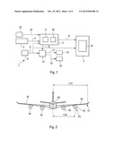
[0044] FIG. 1 is the block diagram of a system for aiding piloting according to the invention.
[0045] FIG. 2 schematically shows an airplane, to which the piloting aiding system according to the invention is applied.
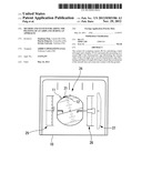
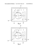
[0046] FIGS. 3 and 4 illustrate displays being able to be implemented by a piloting aiding system according to the invention, respectively in a situation without any risk of striking and a risky situation.
[0047] The system 1 according to the invention and schematically represented on FIG. 1 is intended for aiding a pilot of an airplane AC, in particular a transport airplane, to pilot said airplane AC upon an approach phase, and more specifically during the flare phase, upon a landing to an airport runway. More precisely, it enables including to detect a risk of collision for canopy members with the ground.
[0048] To do so, said system 1 being embedded aboard the airplane AC and operating in real time, comprises: [0049] a set 2 of information sources to automatically determine the current value of a height of the airplane AC relative to the ground and the current value of a pitch angle of said airplane; [0050] a calculation unit 3 being connected thru a connection 4 to said set 2 of information sources and comprising means 5 provided to automatically calculate, from current values received from the set 2 and the geometrical data representative of said airplane AC and related to a limit roll angle φlim being a maximal roll angle up to the value for which it is guaranteed that the end point P1, P2 of the airplane AC will not strike the ground; [0051] usual means 6 for automatically determining the current value of the roll angle of the airplane AC; and [0052] a display 7 being connected thru connections 8 and 9, respectively to said calculation unit 3 and to said means 6 and being adapted to automatically present, on a same screen 10, simultaneously a characteristic sign 11 (for example under the shape of a bar or a herringbone) illustrating said limit roll angle and a characteristic sign 12 (for example under the shape of a triangle) illustrating said current value of the roll angle, as represented on FIGS. 3 and 4.
[0053] In a particular embodiment, said screen 10 is a primary flight screen of the PFD ("Primary Flight Display") type.
[0054] Furthermore, said set 2 of information sources comprises the following means (not represented individually): [0055] at least one usual radiometer to determine the current value of the height of the airplane AC relative to the ground; and [0056] the following usual sensors: pressure sensors, accelerometers, gyrometers, GPS sensors, incidence probes and sideslip probes.
[0057] Thus, the system 1 according to the invention is able to establish at any time upon the approach (more precisely upon the final phase of the approach and the landing) in real time, the roll limit due to the geometry of the airplane AC and the current situation (height, pitch) of the airplane AC, i.e. the limit roll angle, that the airplane can reach without any particular end point of the canopy coming into contact with the ground. Moreover, such value is displayed on a screen 10 within the cockpit of the airplane AC, together with the current value of the roll angle, allowing the pilot to get an exact representation of the possible risk of ground striking (by comparing such two characteristic signs 11 and 12).
[0058] The limit roll angle corresponds, as detailed hereinunder: [0059] either to the tips P1 of the wings W ("wing tip") of the airplane AC; [0060] or to the low ends P2 of the pods of the (external) engines M mounted under the wings of the airplane AC, as represented on FIG. 2.
[0061] The calculation principle implemented by the means 5 is of a geometrical type and it takes three input variables into account: the pitch angle (θ), the roll angle (φ) and the radio altitude HRA of the airplane AC (generally measured at the level of the landing gear). Proper constants for the airplane AC are to be determined and to be provided to said means 5. These variables are necessary to calculate the position of the wing tip or the engine pod end relative to the rotation axes of the airplane AC.
[0062] In a preferred embodiment, said means 5 calculate said limit roll angle φlim by means of the following expressions:
cos2φlim=(-b+b2-4ac)/2a
with:
a=Y12+(HRA+Z2-Z1)2
b=2tgθ(HRA+Z2-Z1)X1
c=tg2θX12-Y12
wherein: [0063] tg represents the tangent: [0064] θ is the pitch angle of the airplane; [0065] HRA is the airplane height relative to the ground, being measured by a radio-altimeter along a measurement direction; [0066] Z2 is the distance along said measurement direction between the centre of gravity of the airplane and the measurement point of the altimeter; and [0067] X1, Y1 and Z1 are geometrical data being representative of said airplane and correspond to the distances between the centre of gravity and said end point, respectively along the three (rotational) axes of a fix bound to the airplane.
[0068] Hereinunder, the definition of the limit roll angle φlim is presented:
[0069] A/ in a first time, the vector corresponding to the end point to be checked is defined. The wings or the engines can be thus checked. In the airplane fix, such vector presents the following components: X1, Y1 and Z1 in the airplane fix. On FIG. 2, there are represented the values Y1A and Y1B de Y1, respectively for the wing tip P1 and for the pod end P2 of the external engine M being the farthest from the longitudinal axis of the airplane AC.
[0070] The height H between the centre of gravity of the airplane AC (relative to which the airplane fix is defined) and the ground corresponds to the following value:
H=[Z2+HRA]cos θcos φ
Z2 being the distance along said measurement direction between the centre of gravity of the airplane AC and the measurement point of the radioaltimeter, which is generally located in the vicinity of the landing gear.
[0071] B/ Calculation of the maximum angle
[0072] It is convenient to calculate the maximum rolls admitted by the projection of the external pod and the wing tip on the plan.
[0073] A strike occurs when the height, in the ground fix, of the wing tip vector is equal to the height between the centre of gravity and the ground. It is thus obtained:
HRA cos θ cos φ+cos θ cos φhlimZ2=cos θ sin φlimY1-sin θX1+cos θ cos φlimZ1
sin φY1=tgθX1+cos φ(HRA+Z2-Z1)
[0074] By making a variable change and squaring such equation, the following solution is obtained:
aX2+bX+c=0
with:
X = cos 2 Φ lim = - b + b 2 - 4 ac 2 a ##EQU00001## a = Y 1 2 + ( HRA + Z 2 - Z 1 ) 2 ##EQU00001.2## b = 2 tg θ ( HRA + Z 2 - Z 1 ) X 1 ##EQU00001.3## c = tg 2 θ X 1 2 - Y 1 2 ##EQU00001.4##
[0075] Furthermore, in a first embodiment, said system comprises in addition: [0076] comparison means 14 to automatically compare the current value of the roll angle (received by the connection 9 of the means 6) with the sum of said limit roll angle (received by a connection 15 of the calculation unit 3) and a predetermined margin; and [0077] means 16, which are connected thru a connection 17 to said comparison means 14 and emit an alarm message (sound and/or visual) intended to warn a pilot of a risky situation of striking, id said current value of the roll angle is higher than said sum.
[0078] Moreover, in a second embodiment (alternatively or in addition to said first embodiment), said system comprises in addition to said comparison means 14 to automatically compare the current value of the roll angle with the sum of said limit roll angle and a predetermined margin, means 18 (connected by a connection 19 to said means (14) in order to automatically control the airplane AC so that the current value of the roll angle becomes again lower than or equal to the sum when it is no longer the case. Such automatic control releases the pilot of any action to come back to a roll secure position, by automatically bringing the roll angle back to the limit, in case of an excess.
[0079] Furthermore, in a particular embodiment, said calculation unit 3 additionally comprises means 20 to perform an estimation of a future value of the roll angle of the airplane AC. In such a case, the display 9 presents in addition on the screen 10 a characteristic sign 21 (preferably an arrow indicating the pending evolution) illustrating said future value of the roll angle (corresponding to the arrow tip on the roll scale).
[0080] Such display of a roll tendency (predicted roll in a near future) allows the pilot to know the margin with respect to the limit and the potential excursions. He can thus be able to identify the risk level.
[0081] Preferably, said means 20 calculate said future value of the roll angle from the derivative of the current value of the roll angle of the airplane, being usually determined with means being for example part of the set 2, and a predetermined prediction time, for instance a few seconds.
[0082] Such roll tendency thus gives, in association with the limit roll angle and the current roll angle, margin information being operational for the pilot.
[0083] Within the present invention, said alarm means 16 and said control means 18 can be associated: [0084] with the single roll excess being detected from the current roll; and [0085] with the single roll excess being detected from the future value of the roll angle; or [0086] preferably simultaneously with two possible roll excesses (related to the current value, and the future value of the roll angle).
[0087] Furthermore, in a particular embodiment, said system 1 comprises moreover an activation unit 23 including for activating the calculation unit 3 (via a connection 22) so as to determine the limit roll angle. Such activation unit 23 comprises the following means (not individually represented): [0088] means for determining, upon the approach, automatically and repetitively, the current value of the height of the airplane AC relative to the ground; [0089] means for comparing such current value to a predetermined height value; and [0090] means for generating the activation as soon as said current height becomes lower than said predetermined height value, for example 40 metres.
[0091] The limit roll information can be displayed in the cockpit, inter alia on the primary flight screen, on a usual roll scale 24, as represented on FIGS. 3 and 4. On these FIGS. 3 and 4, a usual air speed scale 25, a usual altitude scale 26, and a usual vertical speed 27 are also represented. Such limit roll is displayed on the roll scale 24 under the form of the characteristic sign 11 (bar or herringbone). This allows the pilot to be informed when the current roll (characteristic sign 12) exceeds the limit roll indicator (sign 11).
[0092] The future roll is displayed under the form of a tendency arrow 21 being displayed superimposed on the roll information being already displayed in a dynamic way in the cockpit. From the predicted roll angle and limit roll level, the pilot is thus able to identify the risk level. On the example of FIG. 3, no risk appears, whereas, on the example of FIG. 4, the tendency arrow 21 (predicted roll angle) exceeds the authorized limit (sign 11).
[0093] The system 1 according to the invention allows thus detecting in reel time aboard the airplane AC a risk of collision in canopy members with the ground. It enables to display a limit roll to be observed. Depending on the current roll level and the tendency thereof, the pilot can identify the margins and the risks so as to react accordingly. Such limit can also generate an alarm (or an automatic control) if the airplane AC exceeds it.
User Contributions:
Comment about this patent or add new information about this topic:
Images included with this patent application:
 |  |
 |
| Similar patent applications: | |
| Date | Title |
|---|---|
| 2013-07-04 | Method for the intuitive piloting of a drone by means of a remote control |
| 2013-08-22 | Method and system for monitoring the level of oil contained in a tank of an aircraft engine |
| 2013-09-05 | Method and system for calculating and presenting options for planning transportation |
| 2010-08-12 | Method for aiding the taxiing of an aircraft |
| 2013-08-29 | Method for providing the clamping force applied by a parking brake |
| New patent applications in this class: | |
| Date | Title |
|---|---|
| 2016-03-03 | Method and system for recovering the energy state of an aircraft during descent |
| 2015-12-03 | System and method for economizing flight expenditures during aircraft descent and approach |
| 2015-10-29 | Method and system for adjusting the descent trajectory of an aircraft |
| 2015-10-22 | Landing alerts for preventing runway excursions |
| 2015-10-22 | System and method for modulating premature descent protection envelope |
| New patent applications from these inventors: | |
| Date | Title |
|---|---|
| 2016-06-09 | Method and device for estimating the airspeed of an aircraft |
| 2016-01-28 | Method and device for estimating the mach number of an aircraft |
| 2015-03-19 | Method and device for aiding the control of an aircraft during a parabolic flight in order to generate weightlessness in the aircraft |
| 2013-09-12 | Method and apparatus for improved lateral control of an aircraft on the ground during takeoff |
| 2011-12-08 | Device and method for detecting and measuring wind for an aircraft |
| Top Inventors for class "Data processing: vehicles, navigation, and relative location" | |
| Rank | Inventor's name |
|---|---|
| 1 | Anthony H. Heap |
| 2 | Ajith Kuttannair Kumar |
| 3 | Christopher P. Ricci |
| 4 | Roderick A. Hyde |
| 5 | Lowell L. Wood, Jr. |