Patent application title: WIRELESS NETWORK DEVICE CONFIGURATION USING IMAGE CAPTURE
Inventors:
Sreekanth Ravi (Atherton, CA, US)
Sudhakar Ravi (Atherton, CA, US)
Jeremy Zullo (Livermore, CA, US)
Aditya Mavlankar (Foster City, CA, US)
IPC8 Class: AH04N5225FI
USPC Class:
348 1402
Class name: Television two-way video and voice communication (e.g., videophone) over wireless communication
Publication date: 2012-11-15
Patent application number: 20120287219
Abstract:
Apparatus having corresponding methods and non-transitory
computer-readable media comprise: a wireless network adapter; a camera
configured to capture an image; and a processor configured to provide one
or more wireless network parameters based on the image; wherein the
wireless network adapter is configured to connect to a wireless network
according to the wireless network parameters subsequent to the processor
providing the wireless network parameters.Claims:
1. An apparatus comprising: a wireless network adapter; a camera
configured to capture an image; and a processor configured to provide one
or more wireless network parameters based on the image; wherein the
wireless network adapter is configured to connect to a wireless network
according to the wireless network parameters subsequent to the processor
providing the wireless network parameters.
2. The apparatus of claim 1, wherein: the one or more wireless network parameters are encoded in the image.
3. The apparatus of claim 1, wherein the one or more wireless network parameters represent at least one of: a service set identifier (SSID); and a password.
4. The apparatus of claim 1, further comprising: a memory configured to store a symbology, wherein the symbology represents a mapping between image elements and message elements; wherein the processor is further configured to determine elements of one or more messages based on elements of the captured image and the symbology, wherein the one or more messages represent the one or more wireless network parameters; and wherein the processor is further configured to provide the one or more wireless network parameters according to the elements of the one or more messages determined by the processor.
5. A wireless network device comprising the apparatus of claim 1.
6. A video call device comprising the apparatus of claim 1.
7. The apparatus of claim 1, wherein the image represents at least one of: a two-dimensional barcode; a stacked barcode; a circular barcode; and a color barcode.
8. The apparatus of claim 1, wherein the image represents at least one of: a human face; and a fingerprint.
9. A method comprising: capturing an image; providing one or more wireless network parameters based on the image; and connecting to a wireless network according to the wireless network parameters subsequent to providing the wireless network parameters.
10. The method of claim 9, wherein: the one or more wireless network parameters are encoded in the image.
11. The method of claim 9, wherein the one or more wireless network parameters represent at least one of: a service set identifier (SSID); and a password.
12. The method of claim 9, further comprising: storing a symbology, wherein the symbology represents a mapping between image elements and message elements; determining elements of one or more messages based on elements of the captured image and the symbology, wherein the one or more messages represent the one or more wireless network parameters; and providing the one or more wireless network parameters according to the elements of the one or more messages determined.
13. The method of claim 9, wherein the image represents at least one of: a two-dimensional barcode; a stacked barcode; a circular barcode; and a color barcode.
14. The method of claim 9, wherein the image represents at least one of: a human face; and a fingerprint.
15. Non-transitory computer-readable media embodying instructions executable by a computer to perform functions comprising: causing capture of an image; providing one or more wireless network parameters based on the image; and connecting to a wireless network according to the wireless network parameters subsequent to providing the wireless network parameters.
16. The non-transitory computer-readable media of claim 15, wherein: the one or more wireless network parameters are encoded in the image.
17. The non-transitory computer-readable media of claim 15, wherein the one or more wireless network parameters represent at least one of: a service set identifier (SSID); and a password.
18. The non-transitory computer-readable media of claim 15, wherein the functions further comprise: storing a symbology, wherein the symbology represents a mapping between image elements and message elements; determining elements of one or more messages based on elements of the captured image and the symbology, wherein the one or more messages represent the one or more wireless network parameters; and providing the one or more wireless network parameters according to the elements of the one or more messages determined.
19. The non-transitory computer-readable media of claim 15, wherein the image represents at least one of: a two-dimensional barcode; a stacked barcode; a circular barcode; and a color barcode.
20. The non-transitory computer-readable media of claim 15, wherein the image represents at least one of: a human face; and a fingerprint.
Description:
CROSS-REFERENCE TO RELATED APPLICATIONS
[0001] This application claims benefit of U.S. Provisional Patent Application Ser. No. 61/485,229 entitled "MEDIA SHARING DURING A VIDEO CALL," filed May 12, 2011, the disclosure thereof incorporated by reference herein in its entirety.
[0002] This application claims benefit of U.S. Provisional Patent Application Ser. No. 61/485,233 entitled "WIRELESS NETWORK DEVICE CONFIGURATION USING TWO-DIMENSIONAL PATTERNS," filed May 12, 2011, the disclosure thereof incorporated by reference herein in its entirety.
[0003] This application claims benefit of U.S. Provisional Patent Application Ser. No. 61/485,237 entitled "SMART REMOTE CONTROL DEVICES FOR VIDEO CALLING," filed May 12, 2011, the disclosure thereof incorporated by reference herein in its entirety.
[0004] This application is related to U.S. patent application Ser. No. (to be assigned, Attorney Docket No. TLY002001), entitled "MEDIA SHARING DURING A VIDEO CALL," filed TBD, the disclosure thereof incorporated by reference herein in its entirety.
[0005] This application is related to U.S. patent application Ser. No. (to be assigned, Attorney Docket No. TLY004001), entitled "SMART REMOTE CONTROL DEVICES FOR CONTROLLING VIDEO CALL DEVICES," filed TBD, the disclosure thereof incorporated by reference herein in its entirety.
FIELD
[0006] The present disclosure relates generally to wireless network devices. More particularly, the present disclosure relates to the configuration of such devices.
BACKGROUND
[0007] Consumer electronic devices like smartphones or laptop computers that are capable of connecting to wireless networks must be configured with one or more wireless network parameters before connecting to a wireless network. For example, in a conventional WiFi network, the wireless network parameters include the network service set identifier (SSID) and network password. Current wireless consumer electronic devices generally require a user to enter the wireless network parameters manually, for example using a real or virtual keyboard on the device. For some users, this data entry process presents a significant inconvenience.
SUMMARY
[0008] In general, in one aspect, an embodiment features an apparatus comprising: a wireless network adapter; a camera configured to capture an image; and a processor configured to provide one or more wireless network parameters based on the image; wherein the wireless network adapter is configured to connect to a wireless network according to the wireless network parameters subsequent to the processor providing the wireless network parameters.
[0009] Embodiments of the apparatus can include one or more of the following features. In some embodiments, the one or more wireless network parameters are encoded in the image. In some embodiments, the one or more wireless network parameters represent at least one of: a service set identifier (SSID); and a password. Some embodiments comprise a memory configured to store a symbology, wherein the symbology represents a mapping between image elements and message elements; wherein the processor is further configured to determine elements of one or more messages based on elements of the captured image and the symbology, wherein the one or more messages represent the one or more wireless network parameters; and wherein the processor is further configured to provide the one or more wireless network parameters according to the elements of the one or more messages determined by the processor. Some embodiments comprise a wireless network device comprising the apparatus. Some embodiments comprise a video call device comprising the apparatus. In some embodiments, the image represents at least one of: a two-dimensional barcode; a stacked barcode; a circular barcode; and a color barcode. In some embodiments, the image represents at least one of: a human face; and a fingerprint.
[0010] In general, in one aspect, an embodiment features a method comprising: capturing an image; providing one or more wireless network parameters based on the image; and connecting to a wireless network according to the wireless network parameters subsequent to providing the wireless network parameters.
[0011] Embodiments of the method can include one or more of the following features. In some embodiments, the one or more wireless network parameters are encoded in the image. In some embodiments, the one or more wireless network parameters represent at least one of: a service set identifier (SSID); and a password. Some embodiments comprise storing a symbology, wherein the symbology represents a mapping between image elements and message elements; determining elements of one or more messages based on elements of the captured image and the symbology, wherein the one or more messages represent the one or more wireless network parameters; and providing the one or more wireless network parameters according to the elements of the one or more messages determined. In some embodiments, the image represents at least one of: a two-dimensional barcode; a stacked barcode; a circular barcode; and a color barcode. In some embodiments, the image represents at least one of: a human face; and a fingerprint.
[0012] Some embodiments comprise non-transitory computer-readable media embodying instructions executable by a computer to perform functions comprising: causing capture of an image; providing one or more wireless network parameters based on the image; and connecting to a wireless network according to the wireless network parameters subsequent to providing the wireless network parameters.
[0013] Embodiments of the non-transitory computer-readable media can include one or more of the following features. In some embodiments, the one or more wireless network parameters are encoded in the image. In some embodiments, the one or more wireless network parameters represent at least one of: a service set identifier (SSID); and a password. In some embodiments, the functions further comprise: storing a symbology, wherein the symbology represents a mapping between image elements and message elements; determining elements of one or more messages based on elements of the captured image and the symbology, wherein the one or more messages represent the one or more wireless network parameters; and providing the one or more wireless network parameters according to the elements of the one or more messages determined. In some embodiments, the image represents at least one of: a two-dimensional barcode; a stacked barcode; a circular barcode; and a color barcode. In some embodiments, the image represents at least one of: a human face; and a fingerprint.
[0014] The details of one or more implementations are set forth in the accompanying drawings and the description below. Other features will be apparent from the description and drawings, and from the claims.
DESCRIPTION OF DRAWINGS
[0015] FIG. 1 shows elements of a video calling system according to one embodiment.
[0016] FIG. 2 shows elements of a video call device of FIG. 1 according to one embodiment.
[0017] FIG. 3 shows a wireless network device configuration system using image capture according to one embodiment.
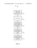
[0018] FIG. 4 shows a wireless network device configuration process for the wireless network device configuration system of FIG. 3 according to one embodiment.
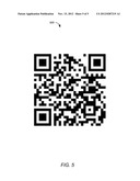
[0019] FIG. 5 shows an example two-dimensional barcode.
[0020] The leading digit(s) of each reference numeral used in this specification indicates the number of the drawing in which the reference numeral first appears.
DETAILED DESCRIPTION
[0021] Embodiments of the present disclosure provide configuration of wireless network devices using image capture. In the described embodiments, the wireless network devices capture images, obtain wireless network parameters from the captured images, and configure their wireless network adapters with the wireless network parameters. Although the wireless network devices are described in terms of video call devices for making video calls, the disclosed embodiments are applicable to any wireless-network-enabled electronic device having a camera. The images can include two-dimensional patterns such as two-dimensional barcodes and the like. Although the images patterns are described in terms of two-dimensional barcodes, the disclosed embodiments are applicable to any image. Before describing these aspects, an example video call device is described.
[0022] Video Call Device
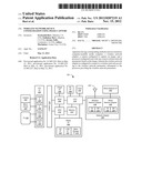
[0023] FIG. 1 shows elements of a video calling system 100 according to one embodiment. Although in the described embodiments the elements of the video calling system 100 are presented in one arrangement, other embodiments may feature other arrangements. For example, elements of the video calling system 100 can be implemented in hardware, software, or combinations thereof.
[0024] Referring to FIG. 1 the video calling system 100 includes N video call devices (video call device) 102A and 102B through 102N connected by a network 108. Network 108 can be implemented as a wide-area network such as the Internet, a local-area network (LAN), or the like. While various embodiments are described with respect to network communications, they also apply to devices employing other forms of data communications such as direct links and the like.
[0025] In the embodiment of FIG. 1, the video call devices 102 do not include display screens or speakers. Therefore each video call device 102 is connected to a respective television set (TV) 106A and 106B through 106N. In other embodiments, one or more of the video call devices 102 includes a display screen and speakers, so one or more television sets 106 are not required. In FIG. 1, each video call device 102 is controlled by one or more respective users, for example using one or more respective remote controls (RC) 110.
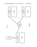
[0026] FIG. 2 shows elements of a video call device 102 of FIG. 1 according to one embodiment. Although in the described embodiments the elements of video call device 102 are presented in one arrangement, other embodiments may feature other arrangements. For example, elements of video call device 102 can be implemented in hardware, software, or combinations thereof.
[0027] Referring to FIG. 2, the video call device 102 includes an audio-visual (AV) interface (I/F) 202, a network adapter 204, a media interface 206, and a remote control (RC) interface 208. The video call device 102 also includes a processor or central processing unit (CPU) 210, a graphical processing unit (GPU) 212, a memory 214, a coder/decoder (CODEC) 218, a multiplexer (MUX) 220, and a clock 222.
[0028] The AV interface 202 includes a video input interface (Video In) 224, an audio input interface (Audio In) 226, a video output interface (Video Out) 228, and an audio output interface (Audio Out) 230. The video input interface 224 can be connected to one or more video capture devices such as a camera 232 or the like. Camera 232 can be implemented as a wide-angle camera that sees the whole room. The audio input interface 226 can be connected to one or more audio capture device such as a microphone 234 or the like. Microphone 234 can be implemented as a noise-cancelling microphone. In some embodiments, video call device 102 includes one or more cameras 232 and/or one or more microphones 234. For example, multiple cameras 232 can be included to generate three-dimensional (3D) video. As another example, multiple microphones 234 can be included so that beamforming techniques can be used to isolate conversations from background noise.
[0029] The video output interface 228 can be connected to a display screen such as that of a television set 106. The audio output interface 230 can be connected to one or more speakers such as those of a television set 106. Alternatively, the video output interface 228 and/or the audio output interface 230 can be connected to the audio-visual inputs of a home theater system or the like. The video output interface 228 and the audio output interface 230 can employ any appropriate connection, for example such as Digital Visual Interface (DVI), High-Definition Multimedia Interface (HDMI), and the like.
[0030] The network adapter 204 includes a wireless network adapter 236 and a wired network adapter 238. In some embodiments, network adapter 204 includes additional communication interfaces, for example including Bluetooth communication interfaces and the like.
[0031] The wireless network adapter 236 includes a transmitter (TX) 240 to transmit wireless signals and a receiver (RX) 242 to receive wireless signals, and is connected to one or more antennas 244. In some embodiments, wireless network adapter 236 is compliant with all or part of IEEE standard 802.11, including draft and approved amendments such as 802.11-1997, 802.11a, 802.11b, 802.11g, 802.11-2007, 802.11n, 802.11-2012, and 802.11ac. For example, the wireless network adapter 236 can allow Wi-Fi connections, for example to a router, to other Wi-Fi devices such as smartphones and computers, and the like.
[0032] The wired network adapter 238 includes a transmitter (TX) 246 to transmit wired signals and a receiver (RX) 248 to transmit wired signals, and is connected to a wired network interface 250. In some embodiments, wired network adapter 238 is compliant with all or part of IEEE standard 802.3, including draft and approved amendments.
[0033] The disclosed video call devices 102 are capable of peer-to-peer (P2P) audio/video communication. Using P2P technology, two video call devices 102 can be connected to each other by one or more networks such that data packets can flow between them. The video call devices 102 can be located anywhere in the world, so long as they are connected by networks 108 such as the Internet. The video call devices 102 can employ multiple communication channels between participants. One channel carries the primary video stream of the video call. Another channel carries the primary audio stream of the video call. A command channel carries commands such as camera commands (for example, pan, tilt, and zoom) and the like. The command channel can also carry synchronization commands to ensure synchronized media playback across multiple sites. Additional channels can employed for other tasks such as media sharing and the like.
[0034] Some available P2P technologies provide multiple communication channels for each video call device 102. The video call device 102 can employ the provided channels and/or channels established outside the chosen P2P technology. P2P technologies generally provide network address translation (NAT) traversal for their channels. The video call devices 102 described herein can provide NAT traversal for channels established outside the chosen P2P technology.
[0035] The media interface 206 receives local media content from external sources, and provides that media content to one or both of processors 210 and 212. In the embodiment of FIG. 2, the media interface 206 includes a Secure Digital (SD) interface 252, a Universal Serial Bus (USB) interface 254, and a mass storage interface 216. Other embodiments can include other interfaces.
[0036] The SD interface 252 receives SD cards, and provides media content stored thereon to the CPU 210 and the GPU 212. The USB interface 254 receives USB devices such as USB memory sticks, USB-cabled devices, and the like, and provides media content from those devices to the CPU 210 and the GPU 212. The USB interface 254 can also receive input devices such as USB dongles for wireless keyboards, wireless pointing devices, and the like. The mass storage interface 216 allows for connection to mass storage devices such as external solid-state drives, disk drives, and the like, and provides media content stored thereon to the CPU 210 and the GPU 212.
[0037] The remote control (RC) interface 208 receives wireless signals such as infrared signals from remote control devices for controlling the video call device 102. In some embodiments, the video call device 102 can be controlled by a wireless device via the wireless network adapter 236.
[0038] The CPU 210 handles general processing functions, while the GPU 212 handles graphic processing functions. In some embodiments, the CPU 210 handles graphic processing functions as well, so the GPU 212 is not required. The CPU 210 receive a time base from clock 222. The memory 214 can be implemented as semiconductor memory and the like.
[0039] The CODEC 218 provides encoding, decoding, and transcoding of the audio and video data handled by the video call device 102. In some embodiments, the CODEC 218 is compliant with one or more standards such as the H.264 standard and the like.
[0040] The MUX 220 allows audio and video to be exchanged via the A/V interface 202, a virtual interface 256, or both. The MUX 220 allows any of the inputs and outputs to be switched with virtual inputs and outputs. For example, audio and video can be provided to and/or from other local devices such as smartphones, portable cameras, document cameras, computer displays of external computers, and the like.
[0041] Wireless Network Configuration Using Image Capture
[0042] Embodiments of the present disclosure provide configuration of wireless network devices using capture of images such as two-dimensional barcodes and the like. Wireless network parameters such as SSID and password are encoded in the image, which is then made available to the camera. For example, a print-out of the image can be held in front of the camera of the wireless network device. As another example, a picture of the image can be displayed on a smart-phone screen or tablet computer screen, which is then held in front of the camera of the wireless network device.
[0043] The camera captures the image. The processor of the wireless network device executes a process to decode the data encoded in the image, and takes appropriate action. For example, the processor analyzes the image to obtain the encoded wireless network parameters, and automatically configures the wireless network device with the wireless network parameters. The wireless network device can then automatically connect to the wireless network.
[0044] The images can include barcodes such as two-dimensional barcodes, stacked barcodes, circular barcodes, color barcodes, and the like. The images can include images of human faces, fingerprints, and the like. For example, facial recognition can be used to identify an image of a face, and a stored association between the identity and associated wireless network parameters can be used to provide the wireless network parameters. The information encoded in the images is not limited to wireless network parameters, but can include other information such as login and password for video calls, contact information for making video calls, promotional codes, reservation times, other configuration information for the wireless network devices, auxiliary device configuration information, virtual private network (VPN) configuration information, group calling information for resuming a previous conversation, and the like.
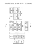
[0045] FIG. 3 shows a wireless network device configuration system 300 using image capture according to one embodiment. Although in the described embodiments the elements of wireless network device configuration system 300 are presented in one arrangement, other embodiments may feature other arrangements. For example, elements of wireless network device configuration system 300 can be implemented in hardware, software, or combinations thereof.
[0046] Referring to FIG. 3, wireless network device configuration system 300 includes a video call device 102, a television (TV) set 106, a wireless network 302, and a card 304 on which is printed an image 306. The image 306 represents wireless network parameters such as a service set identifier (SSID), a password, and the like. The video call device 102 includes a camera 232, a CPU 210, a memory 214, a wireless network adapter 236, and an antenna 244. The memory 214 stores a symbology 308. The wireless network adapter 236 includes a wireless network settings register 310 configured to store the wireless network parameters 312. Once loaded with the proper network parameters, the wireless network adapter 236 can communicate with the wireless network 302. For clarity, some elements of the video call device 102 are not shown in FIG. 3.
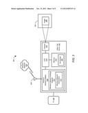
[0047] FIG. 4 shows a wireless network device configuration process 400 for the wireless network device configuration system 300 of FIG. 3 according to one embodiment. Although in the described embodiments the elements of process 400 are presented in one arrangement, other embodiments may feature other arrangements. For example, in various embodiments, some or all of the elements of process 400 can be executed in a different order, concurrently, and the like. Also some elements of process 400 may not be performed, and may not be executed immediately after each other. In addition, some or all of the elements of process 400 can be performed automatically, that is, without human intervention.
[0048] Referring to FIG. 4, at 402 the wireless network device configuration process 400 is initiated. Any method can be used to initiate the wireless network device configuration process 400. In some embodiments, the wireless network device configuration process 400 is initiated by a user, for example using a remote control 110 (FIG. 1) to select the wireless network device configuration process 400 from a menu displayed by the video call device 102 on the connected TV set 106. In some embodiments, the wireless network device configuration process 400 can be started automatically when the video call device 102 is powered on, and a wireless network 108 is available, but no wireless network has been configured.
[0049] Responsive to the initiation of process 400, at 404 the camera 232 of the video call device 102 captures the image 306 printed on the card 304. In the present embodiment, the image 306 is implemented as a two-dimensional barcode. In other embodiments, the image 306 is implemented in other ways, as described herein. FIG. 5 shows an example two-dimensional barcode 500. Referring to FIG. 5, the example two-dimensional barcode 500 includes a plurality of elements arranged as black modules on a white background. In the described embodiment, the elements represent one or more wireless network parameters, which are encoded in the example two-dimensional barcode 500. The elements can include other required elements such as position elements, alignment elements, and the like. The captured image can be stored in the memory 214 of the video call device 102.
[0050] Subsequent to the capture of image 306, the image is decoded to obtain the wireless network parameters encoded therein. The decoding process employs the symbology 308 stored in the memory 214 of the video call device 102. The symbology 308 represents a mapping between image elements and message elements. In the described embodiments, each message element represents one or more characters, and each message represents a string of the characters. However, other sorts of symbologies and mappings can be used instead.
[0051] At 406, the CPU 210 determines elements of one or more messages based on elements of the captured image and the symbology 308 stored in the memory 214 of the video call device 102. The determined elements represent the wireless network parameters encoded in image 306. At 408, the CPU 210 provides the wireless network parameters to the wireless network adapter 236. For example, the CPU 210 writes the wireless network parameters to the wireless network settings register 310 of the wireless network adapter 236. At 410, the wireless network adapter 236 connects to the wireless network 302 according to the wireless network parameters stored in the wireless network settings register 310. The video call device 102 can then communicate over the wireless network 302, for example to connect to other video call devices 102 to conduct video calls, to connect to other wireless electronic devices connected to the wireless network 302, and the like.
[0052] There are several benefits of wireless network device configuration using image capture. First, tedious data entry on the wireless network device can be avoided. The wireless network parameters can be loaded into the bar codes beforehand, for example using a personal computer. The computer can encode the data into an image, and print the image for configuring the wireless network device. This also allows another person, such as a friend or relative, to enter the data to simplify the configuration process for the user. Second, the data in the images can be encoded so the data cannot easily be read by other people present during configuration, thereby providing an additional layer of security.
[0053] Embodiments of the disclosure can be implemented in digital electronic circuitry, or in computer hardware, firmware, software, or in combinations of them. Embodiments of the disclosure can be implemented in a computer program product tangibly embodied in a machine-readable storage device for execution by a programmable processor; and method steps of the disclosure can be performed by a programmable processor executing a program of instructions to perform functions of the disclosure by operating on input data and generating output. The disclosure can be implemented advantageously in one or more computer programs that are executable on a programmable system including at least one programmable processor coupled to receive data and instructions from, and to transmit data and instructions to, a data storage system, at least one input device, and at least one output device. Each computer program can be implemented in a high-level procedural or object-oriented programming language, or in assembly or machine language if desired; and in any case, the language can be a compiled or interpreted language. Suitable processors include, by way of example, both general and special purpose microprocessors. Generally, a processor will receive instructions and data from a read-only memory and/or a random access memory. Generally, a computer will include one or more mass storage devices for storing data files; such devices include magnetic disks, such as internal hard disks and removable disks; magneto-optical disks; and optical disks. Storage devices suitable for tangibly embodying computer program instructions and data include all forms of non-volatile memory, including by way of example semiconductor memory devices, such as EPROM, EEPROM, and flash memory devices; magnetic disks such as internal hard disks and removable disks; magneto-optical disks; and CD-ROM disks. Any of the foregoing can be supplemented by, or incorporated in, ASICs (application-specific integrated circuits).
[0054] A number of implementations of the disclosure have been described. Nevertheless, it will be understood that various modifications may be made without departing from the spirit and scope of the disclosure. Accordingly, other implementations are within the scope of the following claims.
User Contributions:
Comment about this patent or add new information about this topic:
Images included with this patent application:
 |  |
 |  |
 |  |
| Similar patent applications: | |
| Date | Title |
|---|---|
| 2012-11-01 | Image pickup device, visibility support apparatus, night vision device, navigation support apparatus, and monitoring device |
| 2009-12-03 | Multiple sink configuration supporting hdmi-cec |
| 2012-06-14 | Wireless service with photo print feature |
| 2012-10-04 | Real-time depth extraction using stereo correspondence |
| 2012-10-25 | Wireless video conference system and multi-conference switching method thereof |
| New patent applications in this class: | |
| Date | Title |
|---|---|
| 2022-05-05 | Inmate device and user interface for inmate initiated video visitation system |
| 2019-05-16 | Communication and monitoring system |
| 2018-01-25 | Mobile legal counsel system and method |
| 2017-08-17 | Video encoding method and electronic device adapted thereto |
| 2017-08-17 | Methods and systems for dynamic adjustment of session parameters for effective video collaboration among heterogenous devices |
| New patent applications from these inventors: | |
| Date | Title |
|---|---|
| 2012-11-15 | Media sharing during a video call |
| 2012-11-15 | Smart remote control devices for controlling video call devices |
| Top Inventors for class "Television" | |
| Rank | Inventor's name |
|---|---|
| 1 | Canon Kabushiki Kaisha |
| 2 | Kia Silverbrook |
| 3 | Peter Corcoran |
| 4 | Petronel Bigioi |
| 5 | Eran Steinberg |