Patent application title: CONCRETE EXTERIOR WALL SYSTEM
Inventors:
Dean S. Thompson (Lancaster, TN, US)
Robert D. Moss (Lancaster, TN, US)
IPC8 Class: AE04B208FI
USPC Class:
52762
Class name: Static structures (e.g., buildings) facer held by stiffener-type frame facer between exposed frame members having unitary flanges or integral retainer for attachment to frame
Publication date: 2012-10-18
Patent application number: 20120260603
Abstract:
A concrete exterior wall system for residential and commercial
construction incorporates interior wood, metal or composite framing
members. The wall system solves the problem of erecting heavy, hard to
manage solid wall segments as well as time-consuming, complicated
multi-piece wall segments. Further, the wall system eliminates the need
to frame interior walls for utility access, insulation and interior
finishes. Moreover, the wall system eliminates exterior maintenance and
structural damage from weather, insects and the like.
The wall system incorporates wood, metal or composite material interior
framing with a concrete exterior that has a permanent exterior finish.
Interior studs allow easy utility installation and finish applications.
The shape of the wall units are designed for less weight per linear foot
than conventional systems.Claims:
1. A wall system comprising: base concrete segments disposed about a base
of a wall; intermediate concrete segments disposed on top of the base
concrete segments, the intermediate concrete segments also disposed on
top of each other to a predetermined height; top concrete segments
disposed on top of a top row of the intermediate concrete segments; an
exterior finish disposed on the base, intermediate and top concrete
segments; concrete stud sections extending from the exterior finish
toward an inside of the wall system; and framing material inserts
disposed on distal ends of the stud sections.
2. The wall system of claim 1, wherein the concrete stud sections are tapered from a wider end at the exterior finish and a narrower end at the framing material inserts.
3. The wall system of claim 1, further comprising a dovetail joints adapted to interconnect the concrete stud sections with the framing material.
4. The wall system of claim 1, further comprising interlocking tabs disposed on a top side of the concrete stud sections of the base concrete segments and the intermediate concrete segments.
5. The wall system of claim 1, further comprising interlocking notches disposed on a bottom side of the concrete stud sections of the intermediate concrete segments and on a bottom side of the top concrete segments, wherein the interlocking notches interlock with the interlocking tabs to form a vertically aligned assembled framing stud.
6. The wall system of claim 1, further comprising utility access holes disposed in the concrete stud sections.
7. The wall system of claim 1, further comprising a male V-notch at one end of the exterior finish and a female V-notch at an opposite end of the exterior finish.
8. The wall system of claim 1, further comprising reinforcement steel extending from the exterior finish into the concrete stud sections.
9. The wall system of claim 1, wherein the top concrete segment is a U-shaped member adapted to be filled with concrete.
10. The wall system of claim 9, further comprising a base segment disposed along a bottom side of the base concrete segment.
11. The wall system of claim 10, further comprising holes in a bottom portion of the top concrete segment and in the base segment of the base concrete segment, the holes being aligned to permit anchoring segments to extend from the top concrete segment, along a height of the wall, through the base segment, and into a foundation.
12. A wall system comprising: base concrete segments disposed about a base of a wall; intermediate concrete segments disposed on top of the base concrete segments, the intermediate concrete segments also disposed on top of each other to a predetermined height; top concrete segments disposed on top of a top row of the intermediate concrete segments; an exterior finish disposed on the base, intermediate and top concrete segments; concrete stud sections extending from the exterior finish toward an inside of the wall system; framing material inserts disposed on distal ends of the stud sections. interlocking tabs disposed on a top side of the concrete stud sections of the base concrete segments and the intermediate concrete segments; interlocking notches disposed on a bottom side of the concrete stud sections of the intermediate concrete segments and on a bottom side of the top concrete segments, wherein the interlocking notches interlock with the interlocking tabs to form a vertically aligned assembled framing stud; utility access holes disposed in the concrete stud sections; and a male V-notch at one end of the exterior finish and a female V-notch at an opposite end of the exterior finish.
Description:
CROSS-REFERENCE TO RELATED APPLICATIONS
[0001] This application claims the benefit of priority of U.S. provisional patent application number 61/474,383, filed Apr. 12, 2011, the contents of which are herein incorporated by reference.
BACKGROUND OF THE INVENTION
[0002] The present invention relates to exterior wall systems and, more particularly, to a concrete exterior wall system for residential and commercial construction incorporating interior wood, metal or composite framing.
[0003] Current concrete wall systems require large, costly foundations due to extreme weight of products. These wall systems also require long erection time due to complicated multi-piece segments. These wall systems also make insulating the structure costly and difficult.
[0004] After current products are erected, utilities, insulation and interior framing and finishes cannot be easily installed by traditional methods. This increases the cost of the structure due to increased labor and material. There are also severe limitations as to the shape and design of exterior walls with existing systems.
[0005] As can be seen, there is a need for an improved concrete exterior wall system for residential and commercial construction that may incorporate interior wood, metal or composite framing.
SUMMARY OF THE INVENTION
[0006] In one aspect of the present invention, a wall system comprises base concrete segments disposed about a base of a wall; intermediate concrete segments disposed on top of the base concrete segments, the intermediate concrete segments also disposed on top of each other to a predetermined height; top concrete segments disposed on top of a top row of the intermediate concrete segments; an exterior finish disposed on the base, intermediate and top concrete segments; concrete stud sections extending from the exterior finish toward an inside of the wall system; and framing material inserts disposed on distal ends of the stud sections.
[0007] In another aspect of the present invention, a wall system comprises base concrete segments disposed about a base of a wall; intermediate concrete segments disposed on top of the base concrete segments, the intermediate concrete segments also disposed on top of each other to a predetermined height;
[0008] top concrete segments disposed on top of a top row of the intermediate concrete segments; an exterior finish disposed on the base, intermediate and top concrete segments; concrete stud sections extending from the exterior finish toward an inside of the wall system; framing material inserts disposed on distal ends of the stud sections; interlocking tabs disposed on a top side of the concrete stud sections of the base concrete segments and the intermediate concrete segments; interlocking notches disposed on a bottom side of the concrete stud sections of the intermediate concrete segments and on a bottom side of the top concrete segments, wherein the interlocking notches interlock with the interlocking tabs to form a vertically aligned assembled framing stud; utility access holes disposed in the concrete stud sections; and a male V-notch at one end of the exterior finish and a female V-notch at an opposite end of the exterior finish.
[0009] These and other features, aspects and advantages of the present invention will become better understood with reference to the following drawings, description and claims.
BRIEF DESCRIPTION OF THE DRAWINGS
[0010] FIG. 1 is a perspective exploded view of a wall system according to an exemplary embodiment of the present invention;
[0011] FIG. 2 is a perspective view of an intermediate concrete segment of the wall system of FIG. 1;
[0012] FIG. 3 is a cross-sectional view taken along line 3-3 of FIG. 2;
[0013] FIG. 4 is a cross-sectional view taken along line 4-4 of FIG. 2;
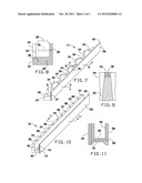
[0014] FIG. 5 is a detailed perspective view of a female end of a V-notch alignment mechanism according to an exemplary embodiment of the present invention;
[0015] FIG. 6 is a detailed perspective view of a male end of a V-notch alignment mechanism according to an exemplary embodiment of the present invention;
[0016] FIG. 7 is a perspective view of a base concrete segment of the wall system of FIG. 1;
[0017] FIG. 8 is a cross-sectional view taken along line 8-8 of FIG. 7;
[0018] FIG. 9 is a cross-sectional view taken along line 9-9 of FIG. 7;
[0019] FIG. 10 is a perspective view of a top concrete segment of the wall system of FIG. 1;
[0020] FIG. 11 is a cross-sectional view taken along line 11-11 of FIG. 10;
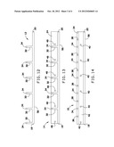
[0021] FIG. 12 is a top view of the intermediate concrete segment of FIG. 2;
[0022] FIG. 13 is a top view of the base concrete segment of FIG. 7;
[0023] FIG. 14 is a top view of the top concrete segment FIG. 10; and
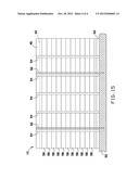
[0024] FIG. 15 is a side view of an assembled wall according to an exemplary embodiment of the present invention.
DETAILED DESCRIPTION OF THE INVENTION
[0025] The following detailed description is of the best currently contemplated modes of carrying out exemplary embodiments of the invention. The description is not to be taken in a limiting sense, but is made merely for the purpose of illustrating the general principles of the invention, since the scope of the invention is best defined by the appended claims.
[0026] Broadly, an embodiment of the present invention provides a concrete exterior wall system for residential and commercial construction that incorporates interior wood, metal or composite framing members. The wall system of the present invention solves the problem of erecting heavy, hard to manage solid wall segments as well as time-consuming, complicated multi-piece wall segments.
[0027] Further, the wall system of the present invention eliminates the need to frame interior walls for utility access, insulation and interior finishes. Moreover, the wall system eliminates exterior maintenance and structural damage from weather, insects and the like. The wall system incorporates wood, metal or composite material interior framing with a concrete exterior that has a permanent exterior finish. Interior studs allow easy utility installation and finish applications. The shape of the wall units are designed for less weight per linear foot than conventional systems.
[0028] Referring now to FIGS. 1 through 15, a concrete wall system 10 may include a base concrete segment 14 adapted to rest on a foundation footing 50.
[0029] The base concrete segment 14 may include a decorative exterior finish 56 and a concrete base 24 disposed along a bottom edge of the base concrete segment 14. A plurality of tapered concrete stud sections 32 may extend from the decorative exterior finish 56 to the inside of the wall system 10. The stud sections 32 may have a framing material insert 34 disposed on an interior side thereof. The framing material insert 34 may be made from conventional framing material, such as wood, metal or composite, for example. The framing material inserts 34 may be connected to the stud sections 32 via a dovetail cut 36, for example.
[0030] Reinforcement steel 26 may extend from the exterior finish 56 into the stud sections 32 as shown in FIG. 3. In addition, reinforcement steel 26 may be disposed to run lengthwise along the concrete base 24 as shown in FIG. 8.
[0031] The ends of the decorative exterior finish 56 may join together with a tongue and groove type of joint. For example, one end of the exterior finish 56 may have a male V-notch, while the opposite end of the exterior finish 56 may have a female V-notch. This joint provides horizontal alignment of adjoining wall segments (such as adjoining base concrete segments 14).
[0032] The wall system 10 may further include a plurality of intermediate concrete segments 12. The intermediate concrete segments 12 may stack on top of each other and on top of the base concrete segment 14. The intermediate concrete segments 12 may include the decorative exterior finish 56 similar to that of the base concrete segments 12. Similar to the base concrete segment 12 described above, the ends of the exterior finish 56 may include male and female V-notches 18, 20. The intermediate concrete segments 12 may include stud sections 32. When the intermediate concrete segments 12 are stacked on each other or on the base concrete segment 14, the stud sections 32 may align to form "studs" on the interior of the wall system 10.
[0033] The stud sections 32 of the base concrete segments 14 and the intermediate concrete segments 12 may have interlocking tabs 28 on a top portion thereof. The stud sections 32 of the intermediate concrete segments 12 may include interlocking notches 30 on a bottom portion thereof. The interlocking notches 30 may align with the interlocking tabs 28 to help align the "studs" vertically.
[0034] In some embodiments, the intermediate concrete segments 12 may include a utility access hole 22 formed through each of the stud sections 32. The utility access holes 22 may be smooth holes to permit utilities, such as plumbing pipes or electrical wires, to pass therethrough.
[0035] A top concrete segment 18 may include the decorative exterior finish similar to the base concrete segments 12 and the intermediate concrete segments 14. Similar to the base concrete segments 12 and the intermediate concrete segments 14 described above, the ends of the exterior finish 56 may include male and female V-notches 18, 20.
[0036] The top concrete segment 18 may be formed in as a generally U-shaped, with a channel 42 adapted to be filled with concrete and reinforcement steel after construction.
[0037] The top concrete segment 18 may include interlocking notches 30 formed along a bottom side thereof to align with the interlocking tabs 28 on the last (top) row of intermediate concrete segments 12. Utility access holes 38 may be provided through the top concrete segment 18 to provide a path for utilities to extend through the top concrete segment 18 to, for example, go into a roof part of a building (not shown).
[0038] The top concrete segment 16 may have a plurality of holes 40 formed along a base thereof. The holes 40 may permit a anchoring segment 52 to run from the top concrete segment 18, into the foundation footing 50, as shown in FIG. 15. Similarly, holes 48 may be formed through the base concrete segment 14 for the anchoring segments 52 to pass therethrough.
[0039] As shown in FIG. 15, a complete wall system 10, as viewed from the inside, may have assembled framing studs 54, typically disposed 16 inches apart, on center. Typically, the ends of the base concrete segments 14, the intermediate concrete segments 12 and the top concrete segment 16 are staggered so that they do not form a continuous seam along the wall. The wall system 10 of the present invention may be used to build various residential and/or commercial structures.
[0040] It should be understood, of course, that the foregoing relates to exemplary embodiments of the invention and that modifications may be made without departing from the spirit and scope of the invention as set forth in the following claims.
User Contributions:
Comment about this patent or add new information about this topic:
Images included with this patent application:
 |  |
 |  |
 |
| Similar patent applications: | |
| Date | Title |
|---|---|
| 2008-12-04 | Interior wall system |
| 2012-07-19 | Concrete sandwich wall insert |
| 2012-12-06 | Connector for boardwalk system |
| 2009-07-30 | Integrated wall system |
| 2010-05-13 | Component wall system |
| New patent applications in this class: | |
| Date | Title |
|---|---|
| 2014-10-16 | Drywall backing apparatus and method of installing same |
| 2014-09-11 | In-situ fabricated wall framing and insulating system |
| 2014-08-21 | Snap-in glass block system |
| 2013-08-08 | System and method for decorating posts |
| 2013-03-28 | Container floor apparatus using wood polymer composite |
| Top Inventors for class "Static structures (e.g., buildings)" | |
| Rank | Inventor's name |
|---|---|
| 1 | Darko Pervan |
| 2 | Gregory F. Jacobs |
| 3 | Husnu M. Kalkanoglu |
| 4 | Ronald P. Hohmann, Jr. |
| 5 | Mark Cappelle |