Patent application title: SYNCHRONOUS REGULATION CIRCUIT FOR TURN-ON AND TURN-OFF PHASE ANGLE OF THE AC VOLTAGE
Inventors:
Tai-Her Yang (Dzan-Hwa, TW)
IPC8 Class: AG05F1455FI
USPC Class:
323239
Class name: Output level responsive phase controlled switching using electronic tube or a three or more terminal semiconductive device including single unidirectional element with bidirectional pass
Publication date: 2012-10-11
Patent application number: 20120256603
Abstract:
The present invention provides a synchronous regulation circuit for
turn-on and turn-off phase angle of the AC voltage, wherein a solid
switch unit is installed between an AC power source and a load, and a
phase angle regulation circuit is utilized to synchronously regulate both
of the turn-on phase angle and turn-off phase angle of the solid switch
unit, so that the sine waveform voltage of the AC power source can be
kept to output in symmetrical waveforms within the range in which the
turn-on and turn-off phase angles being synchronously regulated.Claims:
1. A synchronous regulation circuit for turn-on and turn-off phase angle
of the AC voltage, wherein a solid switch unit is installed between an AC
power source and a load, and a phase angle regulation circuit is utilized
to synchronously regulate both of the turn-on phase angle and turn-off
phase angle of the solid switch unit, so that the sine waveform voltage
of the AC power source can be kept to output in symmetrical waveforms
within the range in which the turn-on and turn-off phase angles being
synchronously regulated; the synchronous regulation circuit for turn-on
and turn-off phase angle of the AC voltage, provided by the present
invention, can be applied to regulate the voltage output by a
single-phase AC power source or a multiphase AC power source, for
supplying power with stable voltage to a load or for regulating the
output current to the load, which mainly consists of: AC current limiting
circuit device (Z10): which is constituted by one or more than one of
resistive impedance, inductive impedance and capacitive impedance being
connected in series, in parallel or in series and parallel and provided
for being connected in series with the load (L101) and the bipolar solid
switch unit (1000) then connected in parallel with the AC power source;
Bipolar solid switch unit (1000): which is constituted by one or more
than one of following solid switch units: 1) The bipolar solid switch
unit (1000) is composed of a bidirectional thyristor component capable of
controlling the turn-on phase angle, e.g. bidirectional silicon
controlled rectifier TRIAC (Triode AC semiconductor switch); through the
regulation function of the regulation circuit of bipolar turn-on and
turn-off phase angle (PD100) itself, a bipolar driving voltage signal is
output to regulate the turn-on phase angle and the turn-off phase angle
of the bipolar solid switch unit (1000) composed of the TRIAC; 2) The
bipolar solid switch unit (1000) is composed of at least two field effect
power components, e.g. a bipolar module composed of the metal oxide
semiconductor field effect transistor (MOSFET) or the insulated gate
bipolar transistor (IGBT); and through the regulation function of the
regulation circuit of bipolar turn-on and turn-off phase angle (PD100)
itself, a bipolar driving voltage signal is output to regulate the
turn-on phase angle and the turn-off phase angle of the bipolar solid
switch unit (1000) composed of at least two field effect power
components; Regulation circuit of bipolar turn-on and turn-off phase
angle (PD100): which is constituted by electronic circuit components for
inputting the AC power voltage; and through the regulation function of
the circuit itself, and with respect to the current value passing the AC
current limiting circuit device (Z10) and the terminal voltage value of
the load (L101), a bipolar driving voltage signal is output to regulate
the turn-on phase angle and the turn-off phase angle of the bipolar solid
switch unit (1000); The mentioned circuit is for regulating the
resistance, the inductive load containing the resistance or the
capacitive load containing the resistance driven by the AC power, or the
load in which the inductive load and the capacitive load containing the
resistance connected in series.
2. A synchronous regulation circuit for turn-on and turn-off phase angle of the AC voltage as claimed in claim 1, wherein it includes configuring the regulation for the turn-on phase angle and the turn-off phase angle to the bipolar solid switch unit, which mainly consists of: AC current limiting circuit device (Z10): which is constituted by one or more than one of resistive impedance, inductive impedance and capacitive impedance being connected in series, in parallel or in series and parallel and provided for being connected in series with the load (L101) and the bipolar solid switch unit (1000) then connected in parallel with the AC power source; Bipolar solid switch unit (1000): which is constituted by one or more than one of following solid switch units: 1) The bipolar solid switch unit (1000) is composed of a bidirectional thyristor component capable of controlling the turn-on phase angle, e.g. bidirectional silicon controlled rectifier TRIAC (Triode AC semiconductor switch); through the configuration function of the configuration circuit of bipolar turn-on and turn-off phase angle (PD200) itself, a bipolar driving voltage signal is output to regulate the turn-on phase angle and the turn-off phase angle of the bipolar solid switch unit (1000) composed of the TRIAC, through the zener diodes (ZD101), (ZD102) which are reverse-polarity connected in series; 2) The bipolar solid switch unit (1000) is composed of at least two field effect power components, e.g. a bipolar module compose of the metal oxide semiconductor field effect transistor (MOSFET) or the integrated gate bipolar transistor (IGBT); and through the configuration function of the configuration circuit of bipolar turn-on and turn-off phase angle (PD200) itself, a bipolar driving voltage signal is output to regulate the turn-on phase angle and the turn-off phase angle of the bipolar solid switch unit (1000) composed of at least two field effect power components, through the zener diodes (ZD101), (ZD102) which are reverse-polarity connected in series; Configuration circuit of bipolar turn-on and turn-off phase angle (PD200): which is constituted by electronic circuit components for inputting the AC power voltage; and through the configuration function of the circuit itself, a bipolar driving voltage signal is output to regulate the turn-on phase angle and the turn-off phase angle of the bipolar solid switch unit (1000) through the zener diodes (ZD101), (ZD102) which are reverse-polarity connected in series; Zener diode (ZD101), (ZD102): which is constituted by at least two zener diodes, reverse-polarity connected in series for generating the bipolar voltage differentiation, and is provided for being connected in series between a bipolar driving voltage signal output terminal of the regulation circuit of bipolar turn-on and turn-off phase angle (PD100) and a bipolar driving voltage signal input terminal of the bipolar solid switch unit (1000); the zener diode (ZD101), (ZD102) can be replaced by a bidirectional zener diode having the same performance; The mentioned circuit is for regulating the resistance, the inductive load containing the resistance or the capacitive load containing the resistance driven by the AC power, or the load in which the inductive load and the capacitive load containing the resistance connected in series.
3. A synchronous regulation circuit for turn-on and turn-off phase angle of the AC voltage as claimed in claim 1, wherein it includes utilizing two bipolar solid switch units for structuring the synchronous regulation for turn-on and turn-off phase angles of the AC voltage, which mainly consists of: AC current limiting circuit device (Z10): which is constituted by one or more than one of resistive impedance, inductive impedance and capacitive impedance being connected in series, in parallel or in series and parallel and provided for being connected in series with the load (L101) and the bipolar solid switch unit (1000) then connected in parallel with the AC power source; Bipolar solid switch unit (1000): which is constituted by a unipolar solid switch unit (1001) and a unipolar solid switch unit (1002) being reverse-polarity connected in parallel; the unipolar solid switch unit (1001) and the unipolar solid switch unit (1002) are composed of one or more than one of following solid switch units: 1) Constituted by at least two unipolar solid switch units (1001, 1002) capable of controlling the turn-on phase angle, e.g. at least two silicon controlled rectifiers (SCRs) being reverse-polarity connected in parallel for forming the bipolar solid switch unit (1000); and through the regulation functions of the regulation circuit of unipolar turn-on and turn-off phase angle (PD101) itself and the regulation circuit of unipolar turn-on and turn-off phase angle (PD102) itself, the driving voltage signals having different polarities are respectively output to control the turn-on phase angle and the turn-off phase angle of the unipolar solid switch unit (1001) and the unipolar solid switch unit (1002); 2) the unipolar solid switch unit (1001) and the unipolar solid switch unit (1002) are composed of at least two field effect power components being reverse-polarity connected in parallel to form the bipolar solid switch unit (1000), e.g. the bipolar module composed of the MOSFET and IGBT serving as the bipolar solid switch unit (1000); and through the regulation functions of the regulation circuit of unipolar turn-on and turn-off phase angle (PD101) itself and the regulation function of the regulation circuit of unipolar turn-on and turn-off phase angle (PD102) itself, the driving voltage signals having different polarities are respectively output to control the turn-on phase angle and the turn-off phase angle of the two field effect power components which are connected in parallel and in different polarities for respectively forming the unipolar solid switch unit (1001) and the unipolar solid switch unit (1002); Regulation circuit of unipolar turn-on and turn-off phase angle (PD101): which is constituted by electronic circuit components and normal-polarity connected in series with the diode (CR101) for inputting an AC voltage of a first polarity; and through the regulation function of the circuit itself and with respect to the current value passing the AC current limiting circuit device (Z10) and the terminal voltage of the load (L101), a driving voltage signal having the same polarity as the unipolar solid switch unit (1001) is output to control the turn-on phase angle and the turn-off phase angle of the unipolar solid switch unit (1001); Configuration circuit of unipolar turn-on and turn-off phase angle (PD102): which is constituted by electronic circuit components and normal-polarity connected in series with the diode (CR102) for inputting an AC voltage of a second polarity; and through the regulation function of the circuit itself and with respect to the current value passing the AC current limiting circuit device (Z10) and the terminal voltage of the load (L101), a driving voltage signal having the same polarity as the unipolar solid switch unit (1002) is output to control the turn-on phase angle and the turn-off phase angle of the unipolar solid switch unit (1002); Diode (CR101): which is constituted by the rectifying diode, and the diode (CR101) and the unipolar solid switch unit (1001) are normal-polarity connected in series with the regulation circuit of unipolar turn-on and turn-off phase angle (PD101); Diode (CR102): which is constituted by the rectifying diode, and the diode (CR102) and the unipolar solid switch unit (1002) are normal-polarity connected in series with the configuration circuit of unipolar turn-on and turn-off phase angle (PD102); The mentioned circuit is for regulating the resistance, the inductive load containing the resistance or the capacitive load containing the resistance driven by the AC power, or the load in which the inductive load and the capacitive load containing the resistance connected in series.
4. A synchronous regulation circuit for turn-on and turn-off phase angle of the AC voltage as claimed in claim 1, wherein it includes configuring the regulation for the turn-on and the turn-off phase angles to two solid switch units, which mainly consists of: AC current limiting circuit device (Z10): which is constituted by one or more than one of resistive impedance, inductive impedance and capacitive impedance being connected in series, in parallel or in series and parallel and provided for being connected in series with the load (L101) and the bipolar solid switch unit (1000) then connected in parallel with the AC power source; Bipolar solid switch unit (1000): which is constituted by a unipolar solid switch unit (1001) and a unipolar solid switch unit (1002) being reverse-polarity connected in parallel; the unipolar solid switch unit (1001) and the unipolar solid switch unit (1002) are composed of one or more than one of following solid switch units: 1) Constituted by at least two unipolar solid switch units (1001, 1002) capable of controlling the turn-on phase angle, e.g. at least two silicon controlled rectifiers (SCRs) being reverse-polarity connected in parallel for forming the bipolar solid switch unit (1000); and through the configuration functions of the configuration circuit of single-polarity turn-on and turn-off phase angle (PD103) itself and the configuration circuit of single-polarity turn-on and turn-off phase angle (PD104) itself, the driving voltage signals having different polarities are respectively output, through the zener diode (ZD103) and the zener diode (ZD104), to the unipolar solid switch unit (1001) and unipolar solid switch unit (1002) for respectively controlling the turn-on phase angle and the turn-off phase angle of the unipolar solid switch unit (1001) and unipolar solid switch unit (1002); 2) the unipolar solid switch unit (1001) and the unipolar solid switch unit (1002) are composed of at least two field effect power components being reverse-polarity connected in parallel to form the bipolar solid switch unit (1000), e.g. the bipolar module composed of the MOSFET and IGBT serving as the bipolar solid switch unit (1000); and through the configuration functions of the configuration circuit of single-polarity turn-on and turn-off phase angle (PD103) itself and the configuration circuit of single-polarity turn-on and turn-off phase angle (PD104) itself, the driving voltage signals having different polarities are respectively output, through the zener diode (ZD103) and the zener diode (ZD104), to the unipolar solid switch unit (1001) and the unipolar solid switch unit (1002) for respectively controlling the turn-on phase angle and the turn-off phase angle of the two field effect power components which are connected in parallel and in different polarities; Configuration circuit of unipolar turn-on and turn-off phase angle (PD103): which is constituted by electronic circuit components and normal-polarity connected in series with the diode (CR101) for inputting an AC voltage of a first polarity; and through the configuration function of the circuit itself, a driving voltage signal having the same polarity as the unipolar solid switch unit (1001) is output to control the turn-on phase angle and the turn-off phase angle of the unipolar solid switch unit (1001); Configuration circuit of unipolar turn-on and turn-off phase angle (PD104): which is constituted by electronic circuit components and normal-polarity connected in series with the diode (CR102) for inputting an AC voltage of a second polarity; and through the configuration function of the circuit itself, a driving voltage signal having the same polarity as the unipolar solid switch unit (1002) is output to control the turn-on phase angle and the turn-off phase angle of the unipolar solid switch unit (1002); Diode (CR101): which is constituted by the rectifying diode, and the diode (CR101) and the unipolar solid switch unit (1001) are normal-polarity connected in series with the regulation circuit of unipolar turn-on and turn-off phase angle (PD101); Diode (CR102): which is constituted by the rectifying diode, and the diode (CR102) and the unipolar solid switch unit (1002) are normal-polarity connected in series with the configuration circuit of unipolar turn-on and turn-off phase angle (PD102); Zener diode (ZD103): which is constituted by the zener diode having zener voltage effect or the forward bias diode for being connected in series between a driving voltage signal output terminal of the configuration circuit of unipolar turn-on and turn-off phase angle (PD103) and a driving voltage signal input terminal of the unipolar solid switch unit (1001); Zener diode (ZD104): which is constituted by the zener diode having zener voltage effect or the forward bias diode for being connected in series between a driving voltage signal output terminal of the configuration circuit of unipolar turn-on and turn-off phase angle (PD104) and a driving voltage signal input terminal of the unipolar solid switch unit (1002); The mentioned circuit is for regulating the resistance, the inductive load containing the resistance or the capacitive load containing the resistance driven by the AC power, or the load in which the inductive load and the capacitive load containing the resistance connected in series.
5. A synchronous regulation circuit for turn-on and turn-off phase angle of the AC voltage as claimed in claim 1, wherein it includes utilizing the bridge rectifiers combining with the solid switch unit for structuring the synchronous regulation circuit for turn-on and turn-off phase angle of the AC voltage, which mainly consists of: AC current limiting circuit device (Z10): which is constituted by one or more than one of resistive impedance, inductive impedance and capacitive impedance being connected in series, in parallel or in series and parallel and provided for being connected in series between the AC power source and an AC input terminal of the bridge rectifier (BR101); Unipolar solid switch unit (1001): which is constituted by one or more than one of following solid switch units: 1) Constituted by the unipolar solid switch unit (1001) capable of controlling the turn-on phase angle, e.g. silicon controlled rectifier (SCR); and through the regulation function of the regulation circuit of unipolar turn-on and turn-off phase angle (PD101) itself, a driving voltage signal is output to control the turn-on phase angle and the turn-off phase angle of the unipolar solid switch unit (1001) composed of silicon controlled rectifier (SCR); 2) the field effect power component serving as the unipolar solid switch unit (1001), e.g. MOSFET and IGBT; and through the regulation function of the regulation circuit of unipolar turn-on and turn-off phase angle (PD101), a driving voltage signal is output to regulate the turn-on phase angle and the turn-off phase angle of the unipolar solid switch unit (1001) composed of the field effect power component; Regulation circuit of unipolar turn-on and turn-off phase angle (PD101): which is constituted by electronic circuit components and provided for being connected in parallel to a DC output terminal of the bridge rectifier (BR102); and through the regulation function of the circuit itself and with respect to the current value passing the AC current limiting circuit device (Z10) and the terminal voltage of the load (L101), a driving voltage signal having the same polarity as the unipolar solid switch unit (1001) is output to control the turn-on phase angle and the turn-off phase angle of the unipolar solid switch unit (1001); Bridge rectifier (BR101): which is constituted by at least four rectifying diodes, in which the AC power input terminal is provided for being connected in series to the AC current limiting circuit device (Z10) so as to be connected to the AC power source, and is provided with the output terminals having anode and cathode of the DC power source; for rectifying the AC power source to DC power source, so as to output to the unipolar solid switch unit (1001) and the load (L101) connected in series; Bridge rectifier (BR102): which is constituted by at least four rectifying diodes and provided with two input terminals for receiving the AC power source and the output terminals having anode and cathode for outputting the DC power source; for rectifying the AC power source to DC power source, so as to output to the regulation circuit of unipolar turn-on and turn-off phase angle (PD101) then further output the driving voltage signal to the unipolar solid switch unit (1001); The mentioned circuit is for regulating the resistance, the inductive load containing the resistance or the capacitive load containing the resistance driven by the AC power, or the load in which the inductive load and the capacitive load containing the resistance connected in series.
6. A synchronous regulation circuit for turn-on and turn-off phase angle of the AC voltage as claimed in claim 1, wherein it includes configuring the regulation for the turn-on and turn-off phase angles to the solid switch unit combined with the bridge rectifiers, which mainly consists of: AC current limiting circuit device (Z10): which is constituted by one or more than one of resistive impedance, inductive impedance and capacitive impedance being connected in series, in parallel or in series and parallel, and one terminal thereof is connected to one terminal of the AC power source, and the other terminal thereof is connected in series with the load (L101) for leading to the AC input terminal of the bridge rectifier (BR101), and the other AC input terminal of the bridge rectifier (BR101) is connected to the other terminal of the AC power source; Unipolar solid switch unit (1001): which is constituted by one or more than one of following solid switch units: 1) Constituted by the unipolar solid switch unit (1001) capable of controlling the turn-on phase angle, e.g. silicon controlled rectifier (SCR); and through the regulation function of the regulation circuit of unipolar turn-on and turn-off phase angle (PD101) itself and with respect to the current value passing the AC current limiting circuit device (Z10) and the terminal voltage value of the load (L101), a driving voltage signal is output, through the zener diode (ZD103), to control the turn-on phase angle and the turn-off phase angle of the unipolar solid switch unit (1001) composed of silicon controlled rectifier (SCR); 2) the field effect power component serving as the unipolar solid switch unit (1001), e.g. MOSFET and IGBT; and through the regulation function of the regulation circuit of unipolar turn-on and turn-off phase angle (PD101) and with respect to the current value passing the AC current limiting circuit device (Z10) and the terminal voltage value of the load (L101), a driving voltage signal is output, through the zener diode (ZD103), to regulate the turn-on phase angle and the turn-off phase angle of the unipolar solid switch unit (1001) composed of the field effect power component; Configuration circuit of unipolar turn-on and turn-off phase angle (PD103): constituted by electronic circuit components and provided for being connected in parallel to the DC output terminal of the bridge rectifier (BR101); through the configuration function of the circuit itself, a driving voltage signal is output, and through the zener diode (ZD103), to control the turn-on phase angle and the turn-off phase angle of the unipolar solid switch unit (1001); Bridge rectifier (BR101): which is constituted by at least four rectifying diodes and provided with two input terminals for receiving the AC power source and the output terminals having anode and cathode for outputting the DC power source; for rectifying the AC power source to DC power source, so as to output to the unipolar switch unit (1001) and the configuration circuit of single-polarity turn-on and turn-off phase angle (PD103); Zener diode (ZD103): which is constituted by the zener diode having zener voltage effect or the forward bias diode for being connected in series between a driving voltage signal output terminal of the configuration circuit of unipolar turn-on and turn-off phase angle (PD103) and a driving voltage signal input terminal of the unipolar solid switch unit (1001); The mentioned circuit is for regulating the resistance, the inductive load containing the resistance or the capacitive load containing the resistance driven by the AC power, or the load in which the inductive load and the capacitive load containing the resistance connected in series.
7. A synchronous regulation circuit for turn-on and turn-off phase angle of the AC voltage as claimed in claim 1, wherein it includes utilizing the bipolar solid switch unit to structure the synchronous regulation for turn-on and turn-off phase angle of the AC voltage, and through the AC current limiting circuit device (Z10) detecting the current value, to output to the regulation circuit of turn-on and turn-off phase angle, thereby to regulate the voltage or current passing the load via the solid switch unit, which mainly consists of: AC current limiting circuit device (Z10): which is constituted by one or more than one of resistive impedance, inductive impedance and capacitive impedance being connected in series, in parallel or in series and parallel and provided for being connected in series with the load (L101) and the bipolar solid switch unit (1000) then connected in parallel with the AC power source; Bipolar solid switch unit (1000): which is constituted by one or more than one of following solid switch units: 1) The bipolar solid switch unit (1000) is composed of a bidirectional thyristor component capable of controlling the turn-on phase angle, e.g. bidirectional silicon controlled rectifier TRIAC (Triode AC semiconductor switch); through the regulation function of the regulation circuit of bipolar turn-on and turn-off phase angle (PD100) itself and with respect to the current value passing the AC current limiting circuit device (Z10) and the terminal voltage of the load (L101), a bipolar driving voltage signal is output to regulate the turn-on phase angle and the turn-off phase angle of the bipolar solid switch unit (1000) composed of the TRIAC; 2) The bipolar solid switch unit (1000) is composed of at least two field effect power components, e.g. a bipolar module composed of the metal oxide semiconductor field effect transistor (MOSFET) or the insulated gate bipolar transistor (IGBT) bipolar solid switch unit; and through the regulation function of the regulation circuit of bipolar turn-on and turn-off phase angle (PD100) itself and with respect to the current value passing the AC current limiting circuit device (Z10) and the terminal voltage of the load (L101), a bipolar driving voltage signal is output to regulate the turn-on phase angle and the turn-off phase angle of the bipolar solid switch unit (1000) composed of at least two field effect power components; Regulation circuit of bipolar turn-on and turn-off phase angle (PD100): which is constituted by electronic circuit components for inputting the AC power voltage; and through the regulation function of the circuit itself, and with respect to the current value passing the AC current limiting circuit device (Z10) and the terminal voltage value of the load (L101), a bipolar driving voltage signal is output to regulate the turn-on phase angle and the turn-off phase angle of the bipolar solid switch unit (1000); The mentioned circuit is for regulating the resistance, the inductive load containing the resistance or the capacitive load containing the resistance driven by the AC power, or the load in which the inductive load and the capacitive load containing the resistance connected in series.
8. A synchronous regulation circuit for turn-on and turn-off phase angle of the AC voltage as claimed in claim 1, wherein it includes utilizing two solid switch units to structure the synchronous regulation for turn-on and turn-off phase angle of the AC voltage, and through the AC current limiting circuit device (Z10) detecting the current value, to output to the regulation circuit of turn-on and turn-off phase angle, thereby to regulate the voltage or current passing the load via the solid switch unit, which mainly consists of: AC current limiting circuit device (Z10): which is constituted by one or more than one of resistive impedance, inductive impedance and capacitive impedance being connected in series, in parallel or in series and parallel and provided for being connected in series with the load (L101) and the bipolar solid switch unit (1000) then connected in parallel with the AC power source; Bipolar solid switch unit (1000): which is constituted by a unipolar solid switch unit (1001) and a unipolar solid switch unit (1002) being reverse-polarity connected in parallel; the unipolar solid switch unit (1001) and the unipolar solid switch unit (1002) are composed of one or more than one of following solid switch units: 1) Constituted by at least two unipolar solid switch units (1001, 1002) capable of controlling the turn-on phase angle, e.g. at least two silicon controlled rectifiers (SCRs) being reverse-polarity connected in parallel for forming the bipolar solid switch unit (1000); and through the regulation functions of the regulation circuit of unipolar turn-on and turn-off phase angle (PD101) itself and the regulation circuit of unipolar turn-on and turn-off phase angle (PD102) itself and with respect to the current value passing the AC current limiting circuit device (Z10) and the terminal voltage value of the load (L101), the driving voltage signals having different polarities are respectively output to control the turn-on phase angle and the turn-off phase angle of the unipolar solid switch unit (1001) and the unipolar solid switch unit (1002); 2) the unipolar solid switch unit (1001) and the unipolar solid switch unit (1002) are composed of at least two field effect power components being reverse-polarity connected in parallel to form the bipolar solid switch unit (1000), e.g. the bipolar module composed of the MOSFET and IGBT serving as the bipolar solid switch unit (1000); and through the regulation functions of the regulation circuit of unipolar turn-on and turn-off phase angle (PD101) itself and the regulation circuit of unipolar turn-on and turn-off phase angle (PD102) itself and with respect to the current value passing the AC current limiting circuit device (Z10) and the terminal voltage value of the load (L101), the driving voltage signals having different polarities are respectively output to control the turn-on phase angle and the turn-off phase angle of the two field effect power components which are connected in parallel and in different polarities for respectively forming the unipolar solid switch unit (1001) and the unipolar solid switch unit (1002); Regulation circuit of unipolar turn-on and turn-off phase angle (PD101): which is constituted by electronic circuit components and normal-polarity connected in series with the diode (CR101) for inputting an AC voltage of a first polarity; and through the regulation function of the circuit itself and with respect to the current value passing the AC current limiting circuit device (Z10) and the terminal voltage of the load (L101), a driving voltage signal having the same polarity as the unipolar solid switch unit (1001) is output to control the turn-on phase angle and the turn-off phase angle of the unipolar solid switch unit (1001); Configuration circuit of unipolar turn-on and turn-off phase angle (PD102): which is constituted by electronic circuit components and normal-polarity connected in series with the diode (CR102) for inputting an AC voltage of a second polarity; and through the regulation function of the circuit itself and with respect to the current value passing the AC current limiting circuit device (Z10) and the terminal voltage of the load (L101), a driving voltage signal having the same polarity as the unipolar solid switch unit (1002) is output to control the turn-on phase angle and the turn-off phase angle of the unipolar solid switch unit (1002); Diode (CR101): which is constituted by the rectifying diode, and the diode (CR101) and the unipolar solid switch unit (1001) are normal-polarity connected in series with the regulation circuit of unipolar turn-on and turn-off phase angle (PD101); Diode (CR102): which is constituted by the rectifying diode, and the diode (CR102) and the unipolar solid switch unit (1002) are normal-polarity connected in series with the configuration circuit of unipolar turn-on and turn-off phase angle (PD102); The mentioned circuit is for regulating the resistance, the inductive load containing the resistance or the capacitive load containing the resistance driven by the AC power, or the load in which the inductive load and the capacitive load containing the resistance connected in series.
9. A synchronous regulation circuit for turn-on and turn-off phase angle of the AC voltage as claimed in claim 1, wherein it includes utilizing the bridge rectifiers combining with the solid switch unit to structure the synchronous regulation for turn-on and turn-off phase angle of the AC voltage, and through the AC current limiting circuit device (Z10) detecting the current value, to output to the regulation circuit of turn-on and turn-off phase angle, and to regulate the voltage or current passing through the load via the solid switch unit, which mainly consists of: AC current limiting circuit device (Z10): which is constituted by one or more than one of resistive impedance, inductive impedance and capacitive impedance being connected in series, in parallel or in series and parallel and provided for being connected in series between the AC power source and an AC input terminal of the bridge rectifier (BR101); Unipolar solid switch unit (1001): which is constituted by one or more than one of following solid switch units: 1) Constituted by the unipolar solid switch unit (1001) capable of controlling the turn-on phase angle, e.g. silicon controlled rectifier (SCR); and through the regulation function of the regulation circuit of unipolar turn-on and turn-off phase angle (PD101) itself and with respect to the current value passing the AC current limiting circuit device (Z10) and the terminal voltage value of the load (L101), a driving voltage signal is output to control the turn-on phase angle and the turn-off phase angle of the unipolar solid switch unit (1001) composed of silicon controlled rectifier (SCR); 2) the field effect power component serving as the unipolar solid switch unit (1001), e.g. MOSFET and IGBT; and through the regulation function of the regulation circuit of unipolar turn-on and turn-off phase angle (PD101) itself and with respect to the current value passing the AC current limiting circuit device (Z10) and the terminal voltage value of the load (L101), a driving voltage signal is output to regulate the turn-on phase angle and the turn-off phase angle of the unipolar solid switch unit (1001) composed of the field effect power component; Regulation circuit of unipolar turn-on and turn-off phase angle (PD101): which is constituted by electronic circuit components, and connected in parallel to a DC output terminal of the bridge rectifier (BR102); and through the regulation function of the circuit itself and with respect to the current value passing the AC current limiting circuit device (Z10) and the terminal voltage of the load (L101), a driving voltage signal having the same polarity as the unipolar solid switch unit (1001) is output to control the turn-on phase angle and the turn-off phase angle of the unipolar solid switch unit (1001); Bridge rectifier (BR101): which is constituted by at least four rectifying diodes, in which the AC power input terminal is provided for being connected in series to the AC current limiting circuit device (Z10) so as to be connected to the AC power source, and is provided with the output terminals having anode and cathode of the DC power source; for rectifying the AC power source to DC power source, so as to output to the unipolar solid switch unit (1001) and the load (L101) connected in series; Bridge rectifier (BR102): which is constituted by at least four rectifying diodes and provided with two input terminals for receiving the AC power source and the output terminals having anode and cathode for outputting the DC power source; for rectifying the AC power source to DC power source, so as to output to the regulation circuit of unipolar turn-on and turn-off phase angle (PD101) then further output the driving voltage signal to the unipolar solid switch unit (1001); The mentioned circuit is for regulating the resistance, the inductive load containing the resistance or the capacitive load containing the resistance driven by the AC power, or the load in which the inductive load and the capacitive load containing the resistance connected in series.
10. A synchronous regulation circuit for turn-on and turn-off phase angle of the AC voltage as claimed in claim 1, wherein the output driving voltage signal of the regulation circuit of bipolar turn-on and turn-off phase angle (PD100), the configuration circuit of bipolar turn-on and turn-off phase angle (PD200), the regulation circuit of unipolar turn-on and turn-off phase angle (PD101) and (PD102), the configuration circuit of unipolar turn-on and turn-off phase angle (PD103) and (PD104) can be constituted by the followings, which includes: 1) Directly outputting the power signal to drive the mated solid switch unit; 2) Utilizing a photoelectric coupling device for insulation and outputting the power signal to drive the mated solid switch unit; and 3) Utilizing a pulse transformer for insulation and outputting the power signal to drive the mated solid switch unit.
Description:
BACKGROUND OF THE INVENTION
[0001] (1) Field of the Invention
[0002] The present invention relates to a synchronous regulation for the turn-on and turn-off phase angles of the sine waveform voltage output by an AC power source, which is a novel regulation mode capable of synchronously regulating the turn-on and turn-off phase angles that breaks through the conventional regulation mode of either regulating the trigger phase angle or regulating the turn-off phase angle, and especially provided with a feature of regulating both of the turn-on and turn-off phase angles with the same phase angle, so that the sine waveform voltage of the AC power source can be kept to output in symmetrical waveforms within the range in which the turn-on and turn-off phase angles being synchronously regulated; the synchronous regulation circuit for turn-on and turn-off phase angle of the AC voltage, provided by the present invention, can be applied to regulate the voltage output by a single-phase AC power source or a multiphase AC power source, for supplying power with stable voltage to a load, or for regulating the output current to the load.
[0003] (2) Description of the Prior Art
[0004] The conventional regulation method for an AC power source is amplitude modulation (as shown in FIG. 1), and till now, the control means for phase angle is to either regulate the trigger phase angle (as shown in FIG. 2), or regulate the turn-off phase angle (as shown in FIG. 3), thereby the application is limited.
SUMMARY OF THE INVENTION
[0005] The present invention provides a synchronous regulation circuit for turn-on and turn-off phase angle of the AC voltage, wherein a solid switch unit is installed between an AC power source and a load, and a phase angle regulation circuit is utilized to synchronously regulate both of the turn-on phase angle and turn-off phase angle of the solid switch unit, so that the sine waveform voltage of the AC power source can be kept to output in symmetrical waveforms within the range in which the turn-on and turn-off phase angles being synchronously regulated; the synchronous regulation circuit for turn-on and turn-off phase angle of the AC voltage, provided by the present invention, can be applied to regulate the voltage output by a single-phase AC power source or a multiphase AC power source, for supplying power with stable voltage to a load or for regulating the output current to the load.
BRIEF DESCRIPTION OF THE DRAWINGS
[0006] FIG. 1 is a schematic view showing the waveform of the conventional amplitude modulation type voltage regulation for the sine-waveform AC voltage.
[0007] FIG. 2 is a schematic view showing the voltage regulation waveform of the conventional regulation for the turn-on phase angle of the sine-waveform AC voltage.
[0008] FIG. 3 is a schematic view showing the voltage regulation waveform of the conventional regulation for the turn-off phase angle of the sine-waveform AC voltage.
[0009] FIG. 4 is a circuit block diagram showing utilizing the bipolar solid switch unit for structuring the synchronous regulation for turn-on and turn-off phase angles of the AC voltage, according to the present invention.
[0010] FIG. 5 is a circuit block diagram showing configuring the regulation for the turn-on phase angle and the turn-off phase angle to the bipolar solid switch unit, according to the present invention.
[0011] FIG. 6 is a circuit block diagram showing utilizing two bipolar solid switch units for structuring the synchronous regulation for turn-on and turn-off phase angles of the AC voltage, according to the present invention.
[0012] FIG. 7 is a circuit block diagram showing configuring the regulation for the turn-on and the turn-off phase angles to two solid switch units, according to the present invention.
[0013] FIG. 8 is a circuit block diagram showing utilizing the bridge rectifiers combining with the solid switch unit for structuring the synchronous regulation circuit for turn-on and turn-off phase angle of the AC voltage.
[0014] FIG. 9 is a circuit block diagram showing configuring the regulation for the turn-on and turn-off phase angles to the solid switch unit combined with the bridge rectifiers, according to the present invention.
[0015] FIG. 10 is a circuit block diagram showing utilizing the bipolar solid switch unit to structure the synchronous regulation for turn-on and turn-off phase angle of the AC voltage, and through the AC current limiting circuit device (Z10) detecting the current value, to output to the regulation circuit of turn-on and turn-off phase angle, thereby to regulate the voltage or current passing the load via the solid switch unit.
[0016] FIG. 11 is a circuit block diagram showing utilizing two solid switch units to structure the synchronous regulation for turn-on and turn-off phase angle of the AC voltage, and through the AC current limiting circuit device (Z10) detecting the current value, to output to the regulation circuit of turn-on and turn-off phase angle, thereby to regulate the voltage or current passing the load via the solid switch unit.
[0017] FIG. 12 is a circuit block diagram showing utilizing the bridge rectifiers combining with the solid switch unit to structure the synchronous regulation for turn-on and turn-off phase angle of the AC voltage, and through the AC current limiting circuit device (Z10) detecting the current value, to output to the regulation circuit of turn-on and turn-off phase angle, and to regulate the voltage or current passing through the load via the solid switch unit.
DESCRIPTION OF MAIN COMPONENT SYMBOLS
[0018] (1000): Bipolar solid switch unit [0019] (1001),(1002): Unipolar solid switch unit [0020] (BR101),(BR102): Bridge rectifier [0021] (CR101),(CR102): Diode [0022] (L101): Load [0023] (PD100): Regulation circuit of bipolar turn-on and turn-off phase angle [0024] (PD200): Configuration circuit of bipolar turn-on and turn-off phase angle [0025] (PD101),(PD102): Regulation circuit of unipolar turn-on and turn-off phase angle [0026] (PD103),(PD104): Configuration circuit of unipolar turn-on and turn-off phase angle [0027] (Z10): AC current limiting circuit device [0028] (ZD101),(ZD102),(ZD103),(ZD104): Zener diode
DETAILED DESCRIPTION OF THE PREFERRED EMBODIMENTS
[0029] The conventional regulation method for an AC power source is amplitude modulation (as shown in FIG. 1), and till now, the control means for phase angle is to either regulate the trigger phase angle (as shown in FIG. 2), or regulate the turn-off phase angle (as shown in FIG. 3), thereby the application is limited.
[0030] The present invention relates to a synchronous regulation for the turn-on and turn-off phase angles of the sine waveform voltage output by an AC power source, which is a novel regulation mode capable of synchronously regulating the turn-on and turn-off phase angles that breaks through the conventional regulation mode of either regulating the trigger phase angle or regulating the turn-off phase angle, and especially provided with a feature of regulating both of the turn-on and turn-off phase angles with the same phase angle, so that the sine-waveform voltage of the AC power source can be kept to output in symmetrical waveforms within the range in which the turn-on and turn-off phase angles being synchronously regulated; the synchronous regulation circuit for turn-on and turn-off phase angle of the AC voltage, provided by the present invention, can be applied to regulate the voltage output by a single-phase AC power source or a multiphase AC power source, for supplying power with stable voltage to a load, or for regulating the output current to the load.
[0031] The present invention provides a synchronous regulation circuit for turn-on and turn-off phase angle of the AC voltage, wherein a solid switch unit is installed between an AC power source and a load, and a phase angle regulation circuit is utilized to synchronously regulate both of the turn-on phase angle and turn-off phase angle of the solid switch unit, so that the sine-waveform voltage of the AC power source can be kept to output in symmetrical waveforms within the range in which the turn-on and turn-off phase angles being synchronously regulated; the synchronous regulation circuit for turn-on and turn-off phase angle of the AC voltage, provided by the present invention, can be applied to regulate the voltage output by a single-phase AC power source or a multiphase AC power source, for supplying power with stable voltage to a load or for regulating the output current to the load.
[0032] FIG. 4 is a circuit block diagram showing utilizing the bipolar solid switch unit for structuring the synchronous regulation for turn-on and turn-off phase angles of the AC voltage, according to the present invention.
[0033] As shown in FIG. 4, it mainly consists of: [0034] AC current limiting circuit device (Z10): which is constituted by one or more than one of resistive impedance, inductive impedance and capacitive impedance being connected in series, in parallel or in series and parallel and provided for being connected in series with the load (L101) and the bipolar solid switch unit (1000) then connected in parallel with the AC power source; [0035] Bipolar solid switch unit (1000): which is constituted by one or more than one of following solid switch units:
[0036] 1) The bipolar solid switch unit (1000) is composed of a bidirectional thyristor component capable of controlling the turn-on phase angle, e.g. bidirectional silicon controlled rectifier TRIAC (Triode AC semiconductor switch); through the regulation function of the regulation circuit of bipolar turn-on and turn-off phase angle (PD100) itself, a bipolar driving voltage signal is output to regulate the turn-on phase angle and the turn-off phase angle of the bipolar solid switch unit (1000) composed of the TRIAC;
[0037] 2) The bipolar solid switch unit (1000) is composed of at least two field effect power components, e.g. a bipolar module composed of the metal oxide semiconductor field effect transistor (MOSFET) or the insulated gate bipolar transistor (IGBT); and through the regulation function of the regulation circuit of bipolar turn-on and turn-off phase angle (PD100) itself, a bipolar driving voltage signal is output to regulate the turn-on phase angle and the turn-off phase angle of the bipolar solid switch unit (1000) composed of at least two field effect power components; [0038] Regulation circuit of bipolar turn-on and turn-off phase angle (PD 100): which is constituted by electronic circuit components for inputting the AC power voltage; and through the regulation function of the circuit itself, and with respect to the current value passing the AC current limiting circuit device (Z10) and the terminal voltage value of the load (L101), a bipolar driving voltage signal is output to regulate the turn-on phase angle and the turn-off phase angle of the bipolar solid switch unit (1000);
[0039] The mentioned circuit is for regulating the resistance, the inductive load containing the resistance or the capacitive load containing the resistance driven by the AC power, or the load in which the inductive load and the capacitive load containing the resistance connected in series.
[0040] FIG. 5 is a circuit block diagram showing configuring the regulation for the turn-on phase angle and the turn-off phase angle to the bipolar solid switch unit, according to the present invention.
[0041] As shown in FIG. 5, it mainly consists of: [0042] AC current limiting circuit device (Z10): which is constituted by one or more than one of resistive impedance, inductive impedance and capacitive impedance being connected in series, in parallel or in series and parallel and provided for being connected in series with the load (L101) and the bipolar solid switch unit (1000) then connected in parallel with the AC power source; [0043] Bipolar solid switch unit (1000): which is constituted by one or more than one of following solid switch units:
[0044] 1) The bipolar solid switch unit (1000) is composed of a bidirectional thyristor component capable of controlling the turn-on phase angle, e.g. bidirectional silicon controlled rectifier TRIAC (Triode AC semiconductor switch); through the configuration function of the configuration circuit of bipolar turn-on and turn-off phase angle (PD200) itself, a bipolar driving voltage signal is output to regulate the turn-on phase angle and the turn-off phase angle of the bipolar solid switch unit (1000) composed of the TRIAC, through the zener diodes (ZD101), (ZD102) which are reverse-polarity connected in series;
[0045] 2) The bipolar solid switch unit (1000) is composed of at least two field effect power components, e.g. a bipolar module compose of the metal oxide semiconductor field effect transistor (MOSFET) or the integrated gate bipolar transistor (IGBT); and through the configuration function of the configuration circuit of bipolar turn-on and turn-off phase angle (PD200) itself, a bipolar driving voltage signal is output to regulate the turn-on phase angle and the turn-off phase angle of the bipolar solid switch unit (1000) composed of at least two field effect power components, through the zener diodes (ZD101), (ZD102) which are reverse-polarity connected in series; [0046] Configuration circuit of bipolar turn-on and turn-off phase angle (PD200): which is constituted by electronic circuit components for inputting the AC power voltage; and through the configuration function of the circuit itself, a bipolar driving voltage signal is output to regulate the turn-on phase angle and the turn-off phase angle of the bipolar solid switch unit (1000) through the zener diodes (ZD101), (ZD102) which are reverse-polarity connected in series; [0047] Zener diode (ZD101), (ZD102): which is constituted by at least two zener diodes, reverse-polarity connected in series for generating the bipolar voltage differentiation, and is provided for being connected in series between a bipolar driving voltage signal output terminal of the regulation circuit of bipolar turn-on and turn-off phase angle (PD100) and a bipolar driving voltage signal input terminal of the bipolar solid switch unit (1000); the zener diode (ZD101), (ZD102) can be replaced by a bidirectional zener diode having the same performance;
[0048] The mentioned circuit is for regulating the resistance, the inductive load containing the resistance or the capacitive load containing the resistance driven by the AC power, or the load in which the inductive load and the capacitive load containing the resistance connected in series.
[0049] FIG. 6 is a circuit block diagram showing utilizing two bipolar solid switch units for structuring the synchronous regulation for turn-on and turn-off phase angles of the AC voltage, according to the present invention.
[0050] As shown in FIG. 6, it mainly consists of: [0051] AC current limiting circuit device (Z10): which is constituted by one or more than one of resistive impedance, inductive impedance and capacitive impedance being connected in series, in parallel or in series and parallel and provided for being connected in series with the load (L101) and the bipolar solid switch unit (1000) then connected in parallel with the AC power source; [0052] Bipolar solid switch unit (1000): which is constituted by a unipolar solid switch unit (1001) and a unipolar solid switch unit (1002) being reverse-polarity connected in parallel; the unipolar solid switch unit (1001) and the unipolar solid switch unit (1002) are composed of one or more than one of following solid switch units:
[0053] 1) Constituted by at least two unipolar solid switch units (1001, 1002) capable of controlling the turn-on phase angle, e.g. at least two silicon controlled rectifiers (SCRs) being reverse-polarity connected in parallel for forming the bipolar solid switch unit (1000); and through the regulation functions of the regulation circuit of unipolar turn-on and turn-off phase angle (PD101) itself and the regulation circuit of unipolar turn-on and turn-off phase angle (PD102) itself, the driving voltage signals having different polarities are respectively output to control the turn-on phase angle and the turn-off phase angle of the unipolar solid switch unit (1001) and the unipolar solid switch unit (1002);
[0054] 2) the unipolar solid switch unit (1001) and the unipolar solid switch unit (1002) are composed of at least two field effect power components being reverse-polarity connected in parallel to form the bipolar solid switch unit (1000), e.g. the bipolar module composed of the MOSFET and IGBT serving as the bipolar solid switch unit (1000); and through the regulation functions of the regulation circuit of unipolar turn-on and turn-off phase angle (PD101) itself and the regulation function of the regulation circuit of unipolar turn-on and turn-off phase angle (PD102) itself, the driving voltage signals having different polarities are respectively output to control the turn-on phase angle and the turn-off phase angle of the two field effect power components which are connected in parallel and in different polarities for respectively forming the unipolar solid switch unit (1001) and the unipolar solid switch unit (1002); [0055] Regulation circuit of unipolar turn-on and turn-off phase angle (PD101): which is constituted by electronic circuit components and normal-polarity connected in series with the diode (CR101) for inputting an AC voltage of a first polarity; and through the regulation function of the circuit itself and with respect to the current value passing the AC current limiting circuit device (Z10) and the terminal voltage of the load (L101), a driving voltage signal having the same polarity as the unipolar solid switch unit (1001) is output to control the turn-on phase angle and the turn-off phase angle of the unipolar solid switch unit (1001); [0056] Configuration circuit of unipolar turn-on and turn-off phase angle (PD102): which is constituted by electronic circuit components and normal-polarity connected in series with the diode (CR102) for inputting an AC voltage of a second polarity; and through the regulation function of the circuit itself and with respect to the current value passing the AC current limiting circuit device (Z10) and the terminal voltage of the load (L101), a driving voltage signal having the same polarity as the unipolar solid switch unit (1002) is output to control the turn-on phase angle and the turn-off phase angle of the unipolar solid switch unit (1002); [0057] Diode (CR101): which is constituted by the rectifying diode, and the diode (CR101) and the unipolar solid switch unit (1001) are normal-polarity connected in series with the regulation circuit of unipolar turn-on and turn-off phase angle (PD101); [0058] Diode (CR102): which is constituted by the rectifying diode, and the diode (CR102) and the unipolar solid switch unit (1002) are normal-polarity connected in series with the configuration circuit of unipolar turn-on and turn-off phase angle (PD102);
[0059] The mentioned circuit is for regulating the resistance, the inductive load containing the resistance or the capacitive load containing the resistance driven by the AC power, or the load in which the inductive load and the capacitive load containing the resistance connected in series.
[0060] FIG. 7 is a circuit block diagram showing configuring the regulation for the turn-on and the turn-off phase angles to two solid switch units, according to the present invention.
[0061] As shown in FIG. 7, it mainly consists of: [0062] AC current limiting circuit device (Z10): which is constituted by one or more than one of resistive impedance, inductive impedance and capacitive impedance being connected in series, in parallel or in series and parallel and provided for being connected in series with the load (L101) and the bipolar solid switch unit (1000) then connected in parallel with the AC power source; [0063] Bipolar solid switch unit (1000): which is constituted by a unipolar solid switch unit (1001) and a unipolar solid switch unit (1002) being reverse-polarity connected in parallel; the unipolar solid switch unit (1001) and the unipolar solid switch unit (1002) are composed of one or more than one of following solid switch units:
[0064] 1) Constituted by at least two unipolar solid switch units (1001, 1002) capable of controlling the turn-on phase angle, e.g. at least two silicon controlled rectifiers (SCRs) being reverse-polarity connected in parallel for forming the bipolar solid switch unit (1000); and through the configuration functions of the configuration circuit of single-polarity turn-on and turn-off phase angle (PD103) itself and the configuration circuit of single-polarity turn-on and turn-off phase angle (PD104) itself, the driving voltage signals having different polarities are respectively output, through the zener diode (ZD103) and the zener diode (ZD104), to the unipolar solid switch unit (1001) and unipolar solid switch unit (1002) for respectively controlling the turn-on phase angle and the turn-off phase angle of the unipolar solid switch unit (1001) and unipolar solid switch unit (1002);
[0065] 2) the unipolar solid switch unit (1001) and the unipolar solid switch unit (1002) are composed of at least two field effect power components being reverse-polarity connected in parallel to form the bipolar solid switch unit (1000), e.g. the bipolar module composed of the MOSFET and IGBT serving as the bipolar solid switch unit (1000); and through the configuration functions of the configuration circuit of single-polarity turn-on and turn-off phase angle (PD103) itself and the configuration circuit of single-polarity turn-on and turn-off phase angle (PD104) itself, the driving voltage signals having different polarities are respectively output, through the zener diode (ZD103) and the zener diode (ZD104), to the unipolar solid switch unit (1001) and the unipolar solid switch unit (1002) for respectively controlling the turn-on phase angle and the turn-off phase angle of the two field effect power components which are connected in parallel and in different polarities; [0066] Configuration circuit of unipolar turn-on and turn-off phase angle (PD103): which is constituted by electronic circuit components and normal-polarity connected in series with the diode (CR101) for inputting an AC voltage of a first polarity; and through the configuration function of the circuit itself, a driving voltage signal having the same polarity as the unipolar solid switch unit (1001) is output to control the turn-on phase angle and the turn-off phase angle of the unipolar solid switch unit (1001); [0067] Configuration circuit of unipolar turn-on and turn-off phase angle (PD104): which is constituted by electronic circuit components and normal-polarity connected in series with the diode (CR102) for inputting an AC voltage of a second polarity; and through the configuration function of the circuit itself, a driving voltage signal having the same polarity as the unipolar solid switch unit (1002) is output to control the turn-on phase angle and the turn-off phase angle of the unipolar solid switch unit (1002); [0068] Diode (CR101): which is constituted by the rectifying diode, and the diode (CR101) and the unipolar solid switch unit (1001) are normal-polarity connected in series with the regulation circuit of unipolar turn-on and turn-off phase angle (PD101); [0069] Diode (CR102): which is constituted by the rectifying diode, and the diode (CR102) and the unipolar solid switch unit (1002) are normal-polarity connected in series with the configuration circuit of unipolar turn-on and turn-off phase angle (PD102); [0070] Zener diode (ZD103): which is constituted by the zener diode having zener voltage effect or the forward bias diode for being connected in series between a driving voltage signal output terminal of the configuration circuit of unipolar turn-on and turn-off phase angle (PD103) and a driving voltage signal input terminal of the unipolar solid switch unit (1001); [0071] Zener diode (ZD104): which is constituted by the zener diode having zener voltage effect or the forward bias diode for being connected in series between a driving voltage signal output terminal of the configuration circuit of unipolar turn-on and turn-off phase angle (PD104) and a driving voltage signal input terminal of the unipolar solid switch unit (1002);
[0072] The mentioned circuit is for regulating the resistance, the inductive load containing the resistance or the capacitive load containing the resistance driven by the AC power, or the load in which the inductive load and the capacitive load containing the resistance connected in series.
[0073] FIG. 8 is a circuit block diagram showing utilizing the bridge rectifiers combining with the solid switch unit for structuring the synchronous regulation circuit for turn-on and turn-off phase angle of the AC voltage.
[0074] As shown in FIG. 8, it mainly consists of: [0075] AC current limiting circuit device (Z10): which is constituted by one or more than one of resistive impedance, inductive impedance and capacitive impedance being connected in series, in parallel or in series and parallel and provided for being connected in series between the AC power source and an AC input terminal of the bridge rectifier (BR101); [0076] Unipolar solid switch unit (1001): which is constituted by one or more than one of following solid switch units:
[0077] 1) Constituted by the unipolar solid switch unit (1001) capable of controlling the turn-on phase angle, e.g. silicon controlled rectifier (SCR); and through the regulation function of the regulation circuit of unipolar turn-on and turn-off phase angle (PD101) itself, a driving voltage signal is output to control the turn-on phase angle and the turn-off phase angle of the unipolar solid switch unit (1001) composed of silicon controlled rectifier (SCR);
[0078] 2) the field effect power component serving as the unipolar solid switch unit (1001), e.g. MOSFET and IGBT; and through the regulation function of the regulation circuit of unipolar turn-on and turn-off phase angle (PD101), a driving voltage signal is output to regulate the turn-on phase angle and the turn-off phase angle of the unipolar solid switch unit (1001) composed of the field effect power component; [0079] Regulation circuit of unipolar turn-on and turn-off phase angle (PD101): which is constituted by electronic circuit components and provided for being connected in parallel to a DC output terminal of the bridge rectifier (BR102); and through the regulation function of the circuit itself and with respect to the current value passing the AC current limiting circuit device (Z10) and the terminal voltage of the load (L101), a driving voltage signal having the same polarity as the unipolar solid switch unit (1001) is output to control the turn-on phase angle and the turn-off phase angle of the unipolar solid switch unit (1001); [0080] Bridge rectifier (BR101): which is constituted by at least four rectifying diodes, in which the AC power input terminal is provided for being connected in series to the AC current limiting circuit device (Z10) so as to be connected to the AC power source, and is provided with the output terminals having anode and cathode of the DC power source; for rectifying the AC power source to DC power source, so as to output to the unipolar solid switch unit (1001) and the load (L101) connected in series; [0081] Bridge rectifier (BR102): which is constituted by at least four rectifying diodes and provided with two input terminals for receiving the AC power source and the output terminals having anode and cathode for outputting the DC power source; for rectifying the AC power source to DC power source, so as to output to the regulation circuit of unipolar turn-on and turn-off phase angle (PD101) then further output the driving voltage signal to the unipolar solid switch unit (1001);
[0082] The mentioned circuit is for regulating the resistance, the inductive load containing the resistance or the capacitive load containing the resistance driven by the AC power, or the load in which the inductive load and the capacitive load containing the resistance connected in series.
[0083] FIG. 9 is a circuit block diagram showing configuring the regulation for the turn-on and turn-off phase angles to the solid switch unit combined with the bridge rectifiers, according to the present invention.
[0084] As shown in FIG. 9, it mainly consists of: [0085] AC current limiting circuit device (Z10): which is constituted by one or more than one of resistive impedance, inductive impedance and capacitive impedance being connected in series, in parallel or in series and parallel, and one terminal thereof is connected to one terminal of the AC power source, and the other terminal thereof is connected in series with the load (L101) for leading to the AC input terminal of the bridge rectifier (BR101), and the other AC input terminal of the bridge rectifier (BR101) is connected to the other terminal of the AC power source; [0086] Unipolar solid switch unit (1001): which is constituted by one or more than one of following solid switch units:
[0087] 1) Constituted by the unipolar solid switch unit (1001) capable of controlling the turn-on phase angle, e.g. silicon controlled rectifier (SCR); and through the regulation function of the regulation circuit of unipolar turn-on and turn-off phase angle (PD101) itself and with respect to the current value passing the AC current limiting circuit device (Z10) and the terminal voltage value of the load (L101), a driving voltage signal is output, through the zener diode (ZD103), to control the turn-on phase angle and the turn-off phase angle of the unipolar solid switch unit (1001) composed of silicon controlled rectifier (SCR);
[0088] 2) the field effect power component serving as the unipolar solid switch unit (1001), e.g. MOSFET and IGBT; and through the regulation function of the regulation circuit of unipolar turn-on and turn-off phase angle (PD101) and with respect to the current value passing the AC current limiting circuit device (Z10) and the terminal voltage value of the load (L101), a driving voltage signal is output, through the zener diode (ZD103), to regulate the turn-on phase angle and the turn-off phase angle of the unipolar solid switch unit (1001) composed of the field effect power component; [0089] Configuration circuit of unipolar turn-on and turn-off phase angle (PD103): constituted by electronic circuit components and provided for being connected in parallel to the DC output terminal of the bridge rectifier (BR101); through the configuration function of the circuit itself, a driving voltage signal is output, and through the zener diode (ZD103), to control the turn-on phase angle and the turn-off phase angle of the unipolar solid switch unit (1001); [0090] Bridge rectifier (BR101): which is constituted by at least four rectifying diodes and provided with two input terminals for receiving the AC power source and the output terminals having anode and cathode for outputting the DC power source; for rectifying the AC power source to DC power source, so as to output to the unipolar switch unit (1001) and the configuration circuit of single-polarity turn-on and turn-off phase angle (PD103); [0091] Zener diode (ZD103): which is constituted by the zener diode having zener voltage effect or the forward bias diode for being connected in series between a driving voltage signal output terminal of the configuration circuit of unipolar turn-on and turn-off phase angle (PD103) and a driving voltage signal input terminal of the unipolar solid switch unit (1001);
[0092] The mentioned circuit is for regulating the resistance, the inductive load containing the resistance or the capacitive load containing the resistance driven by the AC power, or the load in which the inductive load and the capacitive load containing the resistance connected in series.
[0093] FIG. 10 is a circuit block diagram showing utilizing the bipolar solid switch unit to structure the synchronous regulation for turn-on and turn-off phase angle of the AC voltage, and through the AC current limiting circuit device (Z10) detecting the current value, to output to the regulation circuit of turn-on and turn-off phase angle, thereby to regulate the voltage or current passing the load via the solid switch unit.
[0094] As shown in FIG. 10, it mainly consists of: [0095] AC current limiting circuit device (Z10): which is constituted by one or more than one of resistive impedance, inductive impedance and capacitive impedance being connected in series, in parallel or in series and parallel and provided for being connected in series with the load (L101) and the bipolar solid switch unit (1000) then connected in parallel with the AC power source; [0096] Bipolar solid switch unit (1000): which is constituted by one or more than one of following solid switch units:
[0097] 1) The bipolar solid switch unit (1000) is composed of a bidirectional thyristor component capable of controlling the turn-on phase angle, e.g. bidirectional silicon controlled rectifier TRIAC (Triode AC semiconductor switch); through the regulation function of the regulation circuit of bipolar turn-on and turn-off phase angle (PD100) itself and with respect to the current value passing the AC current limiting circuit device (Z10) and the terminal voltage of the load (L101), a bipolar driving voltage signal is output to regulate the turn-on phase angle and the turn-off phase angle of the bipolar solid switch unit (1000) composed of the TRIAC;
[0098] 2) The bipolar solid switch unit (1000) is composed of at least two field effect power components, e.g. a bipolar module composed of the metal oxide semiconductor field effect transistor (MOSFET) or the insulated gate bipolar transistor (IGBT) bipolar solid switch unit; and through the regulation function of the regulation circuit of bipolar turn-on and turn-off phase angle (PD100) itself and with respect to the current value passing the AC current limiting circuit device (Z10) and the terminal voltage of the load (L101), a bipolar driving voltage signal is output to regulate the turn-on phase angle and the turn-off phase angle of the bipolar solid switch unit (1000) composed of at least two field effect power components; [0099] Regulation circuit of bipolar turn-on and turn-off phase angle (PD100): which is constituted by electronic circuit components for inputting the AC power voltage; and through the regulation function of the circuit itself, and with respect to the current value passing the AC current limiting circuit device (Z10) and the terminal voltage value of the load (L101), a bipolar driving voltage signal is output to regulate the turn-on phase angle and the turn-off phase angle of the bipolar solid switch unit (1000);
[0100] The mentioned circuit is for regulating the resistance, the inductive load containing the resistance or the capacitive load containing the resistance driven by the AC power, or the load in which the inductive load and the capacitive load containing the resistance connected in series.
[0101] FIG. 11 is a circuit block diagram showing utilizing two solid switch units to structure the synchronous regulation for turn-on and turn-off phase angle of the AC voltage, and through the AC current limiting circuit device (Z10) detecting the current value, to output to the regulation circuit of turn-on and turn-off phase angle, thereby to regulate the voltage or current passing the load via the solid switch unit.
[0102] As shown in FIG. 11, it mainly consists of: [0103] AC current limiting circuit device (Z10): which is constituted by one or more than one of resistive impedance, inductive impedance and capacitive impedance being connected in series, in parallel or in series and parallel and provided for being connected in series with the load (L101) and the bipolar solid switch unit (1000) then connected in parallel with the AC power source; [0104] Bipolar solid switch unit (1000): which is constituted by a unipolar solid switch unit (1001) and a unipolar solid switch unit (1002) being reverse-polarity connected in parallel; the unipolar solid switch unit (1001) and the unipolar solid switch unit (1002) are composed of one or more than one of following solid switch units: [0105] 1) Constituted by at least two unipolar solid switch units (1001, 1002) capable of controlling the turn-on phase angle, e.g. at least two silicon controlled rectifiers (SCRs) being reverse-polarity connected in parallel for forming the bipolar solid switch unit (1000); and through the regulation functions of the regulation circuit of unipolar turn-on and turn-off phase angle (PD101) itself and the regulation circuit of unipolar turn-on and turn-off phase angle (PD102) itself and with respect to the current value passing the AC current limiting circuit device (Z10) and the terminal voltage value of the load (L101), the driving voltage signals having different polarities are respectively output to control the turn-on phase angle and the turn-off phase angle of the unipolar solid switch unit (1001) and the unipolar solid switch unit (1002); [0106] 2) the unipolar solid switch unit (1001) and the unipolar solid switch unit (1002) are composed of at least two field effect power components being reverse-polarity connected in parallel to form the bipolar solid switch unit (1000), e.g. the bipolar module composed of the MOSFET and IGBT serving as the bipolar solid switch unit (1000); and through the regulation functions of the regulation circuit of unipolar turn-on and turn-off phase angle (PD101) itself and the regulation circuit of unipolar turn-on and turn-off phase angle (PD102) itself and with respect to the current value passing the AC current limiting circuit device (Z10) and the terminal voltage value of the load (L101), the driving voltage signals having different polarities are respectively output to control the turn-on phase angle and the turn-off phase angle of the two field effect power components which are connected in parallel and in different polarities for respectively forming the unipolar solid switch unit (1001) and the unipolar solid switch unit (1002); [0107] Regulation circuit of unipolar turn-on and turn-off phase angle (PD101): which is constituted by electronic circuit components and normal-polarity connected in series with the diode (CR101) for inputting an AC voltage of a first polarity; and through the regulation function of the circuit itself and with respect to the current value passing the AC current limiting circuit device (Z10) and the terminal voltage of the load (L101), a driving voltage signal having the same polarity as the unipolar solid switch unit (1001) is output to control the turn-on phase angle and the turn-off phase angle of the unipolar solid switch unit (1001); [0108] Configuration circuit of unipolar turn-on and turn-off phase angle (PD102): which is constituted by electronic circuit components and normal-polarity connected in series with the diode (CR102) for inputting an AC voltage of a second polarity; and through the regulation function of the circuit itself and with respect to the current value passing the AC current limiting circuit device (Z10) and the terminal voltage of the load (L101), a driving voltage signal having the same polarity as the unipolar solid switch unit (1002) is output to control the turn-on phase angle and the turn-off phase angle of the unipolar solid switch unit (1002); [0109] Diode (CR101): which is constituted by the rectifying diode, and the diode (CR101) and the unipolar solid switch unit (1001) are normal-polarity connected in series with the regulation circuit of unipolar turn-on and turn-off phase angle (PD101); [0110] Diode (CR102): which is constituted by the rectifying diode, and the diode (CR102) and the unipolar solid switch unit (1002) are normal-polarity connected in series with the configuration circuit of unipolar turn-on and turn-off phase angle (PD102);
[0111] The mentioned circuit is for regulating the resistance, the inductive load containing the resistance or the capacitive load containing the resistance driven by the AC power, or the load in which the inductive load and the capacitive load containing the resistance connected in series.
[0112] FIG. 12 is a circuit block diagram showing utilizing the bridge rectifiers combining with the solid switch unit to structure the synchronous regulation for turn-on and turn-off phase angle of the AC voltage, and through the AC current limiting circuit device (Z10) detecting the current value, to output to the regulation circuit of turn-on and turn-off phase angle, and to regulate the voltage or current passing through the load via the solid switch unit.
[0113] As shown in FIG. 12, it mainly consists of: [0114] AC current limiting circuit device (Z10): which is constituted by one or more than one of resistive impedance, inductive impedance and capacitive impedance being connected in series, in parallel or in series and parallel and provided for being connected in series between the AC power source and an AC input terminal of the bridge rectifier (BR101); [0115] Unipolar solid switch unit (1001): which is constituted by one or more than one of following solid switch units:
[0116] 1) Constituted by the unipolar solid switch unit (1001) capable of controlling the turn-on phase angle, e.g. silicon controlled rectifier (SCR); and through the regulation function of the regulation circuit of unipolar turn-on and turn-off phase angle (PD101) itself and with respect to the current value passing the AC current limiting circuit device (Z10) and the terminal voltage value of the load (L101), a driving voltage signal is output to control the turn-on phase angle and the turn-off phase angle of the unipolar solid switch unit (1001) composed of silicon controlled rectifier (SCR);
[0117] 2) the field effect power component serving as the unipolar solid switch unit (1001), e.g. MOSFET and IGBT; and through the regulation function of the regulation circuit of unipolar turn-on and turn-off phase angle (PD101) itself and with respect to the current value passing the AC current limiting circuit device (Z10) and the terminal voltage value of the load (L101), a driving voltage signal is output to regulate the turn-on phase angle and the turn-off phase angle of the unipolar solid switch unit (1001) composed of the field effect power component; [0118] Regulation circuit of unipolar turn-on and turn-off phase angle (PD101): which is constituted by electronic circuit components, and connected in parallel to a DC output terminal of the bridge rectifier (BR102); and through the regulation function of the circuit itself and with respect to the current value passing the AC current limiting circuit device (Z10) and the terminal voltage of the load (L101), a driving voltage signal having the same polarity as the unipolar solid switch unit (1001) is output to control the turn-on phase angle and the turn-off phase angle of the unipolar solid switch unit (1001); [0119] Bridge rectifier (BR101): which is constituted by at least four rectifying diodes, in which the AC power input terminal is provided for being connected in series to the AC current limiting circuit device (Z10) so as to be connected to the AC power source, and is provided with the output terminals having anode and cathode of the DC power source; for rectifying the AC power source to DC power source, so as to output to the unipolar solid switch unit (1001) and the load (L101) connected in series; [0120] Bridge rectifier (BR102): which is constituted by at least four rectifying diodes and provided with two input terminals for receiving the AC power source and the output terminals having anode and cathode for outputting the DC power source; for rectifying the AC power source to DC power source, so as to output to the regulation circuit of unipolar turn-on and turn-off phase angle (PD101) then further output the driving voltage signal to the unipolar solid switch unit (1001);
[0121] The mentioned circuit is for regulating the resistance, the inductive load containing the resistance or the capacitive load containing the resistance driven by the AC power, or the load in which the inductive load and the capacitive load containing the resistance connected in series.
[0122] According to the synchronous regulation circuit for turn-on and turn-off phase angle of the AC voltage provided by the present invention, the output driving voltage signal of the regulation circuit of bipolar turn-on and turn-off phase angle (PD100), the configuration circuit of bipolar turn-on and turn-off phase angle (PD200), the regulation circuit of unipolar turn-on and turn-off phase angle (PD101) and (PD102), the configuration circuit of unipolar turn-on and turn-off phase angle (PD103) and (PD104) can be constituted by the followings, which includes:
[0123] 1) Directly outputting the power signal to drive the mated solid switch unit;
[0124] 2) Utilizing a photoelectric coupling device for insulation and outputting the power signal to drive the mated solid switch unit; and
[0125] 3) Utilizing a pulse transformer for insulation and outputting the power signal to drive the mated solid switch unit.
User Contributions:
Comment about this patent or add new information about this topic:
Images included with this patent application:
 | 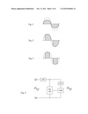 |
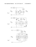 | 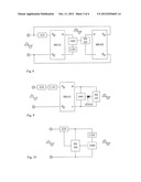 |
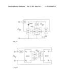 |
| Similar patent applications: | |
| Date | Title |
|---|---|
| 2013-10-03 | Bandgap reference circuit for providing reference voltage |
| 2013-10-10 | Power conversion device, control device for power conversion device, and control method for power conversion device |
| 2009-04-30 | Charging circuit for a vehicle charger |
| 2013-10-10 | Semiconductor driver circuit and power conversion device |
| 2013-10-03 | Constant-on-time generation circuit and buck converter |
| Top Inventors for class "Electricity: power supply or regulation systems" | |
| Rank | Inventor's name |
|---|---|
| 1 | Weihong Qiu |
| 2 | Benjamim Tang |
| 3 | Qian Ouyang |
| 4 | Ta-Yung Yang |
| 5 | John L. Melanson |