Patent application title: ASSEMBLED MAGNETIC TRACK STRUCUTRE FOR TOY VEHICLE
Inventors:
Hsu-Chu Lin (New Taipei City, TW)
Po-Jen Wu (New Taipei City, TW)
Assignees:
Cinken Co., Ltd.
IPC8 Class: AA63H3326FI
USPC Class:
446138
Class name: Having permanent magnet (not motor associated) contacting, mutually attracted members contact maintained during relative movement
Publication date: 2012-10-04
Patent application number: 20120252310
Abstract:
An assembled magnetic track structure for a toy vehicle includes a base
plate disposed on a ground, and a magnetic track magnetically attracted
to the base plate. The magnetic track is made by assembling a plurality
of magnetic track sections. Wheels of the toy vehicle run on the magnetic
track. By this structure, it is easy for manufacturing, saves the expense
of molds, and reduces the production cost and selling cost. Further, it
can be assembled easily and freely to increase the interest and
variability thereof.Claims:
1. An assembled magnetic track structure for a toy vehicle, including: a
base plate disposed on a ground; and a magnetic track magnetically
attracted to the base plate, a wheel of the toy vehicle running on the
magnetic track.
2. The assembled magnetic track structure for a toy vehicle according to claim 1, wherein the base plate has an inner iron sheet, the magnetic track is made of an integral magnetic element and magnetically attracted to the inner iron sheet.
3. The assembled magnetic track structure for a toy vehicle according to claim 1, wherein the base plate has an inner iron sheet, the magnetic track is made by assembling a plurality of magnetic track sections, each of the magnetic track sections is made of a magnetic element and magnetically attracted to the inner iron sheet.
4. The assembled magnetic track structure for a toy vehicle according to claim 3, wherein the magnetic element is one selected from a group including rigid magnets and soft magnets.
5. The assembled magnetic track structure for a toy vehicle according to claim 1, wherein the base plate has an inner iron sheet, the magnetic track is made by assembling a plurality of magnetic track sections, each of the magnetic track sections comprises a non-magnetic body and magnets adhered to the non-magnetic body, the magnetic track sections are magnetically attracted to the inner iron sheet.
6. The assembled magnetic track structure for a toy vehicle according to claim 1, wherein the base plate has an inner iron sheet, the magnetic track is made by assembling a plurality of magnetic pieces, gaps between any two magnetic pieces are connected to form the magnetic track, each of the magnetic pieces is made of a magnetic element and magnetically attracted to the inner iron sheet.
7. The assembled magnetic track structure for a toy vehicle according to claim 6, wherein the base plate further has an outer pattern layer adhered to the outside of the inner iron sheet.
8. The assembled magnetic track structure for a toy vehicle according to claim 2, wherein the magnetic track is configured to have a width allowing wheels of the toy vehicle to straddle thereon, the magnetic track is configured to guide the toy vehicle to run on the magnetic track.
9. The assembled magnetic track structure for a toy vehicle according to claim 3, wherein the magnetic track is configured to have a width allowing wheels of the toy vehicle to straddle thereon, the magnetic track is configured to guide the toy vehicle to run on the magnetic track.
10. The assembled magnetic track structure for a toy vehicle according to claim 2, further including at least one decorative element magnetically attracted to the base plate by magnets.
11. The assembled magnetic track structure for a toy vehicle according to claim 3, further including at least one decorative element magnetically attracted to the base plate by magnets.
12. The assembled magnetic track structure for a toy vehicle according to claim 2, further including at least one magnetic fixing strip for connecting a plurality of base plates, the magnetic fixing strip being made of a magnetic element and magnetically attracted to a bottom surface of the base plate near the ground.
13. The assembled magnetic track structure for a toy vehicle according to claim 3, further including at least one magnetic fixing strip for connecting a plurality of base plates, the magnetic fixing strip being made of a magnetic element and magnetically attracted to a bottom surface of the base plate near the ground.
14. The assembled magnetic track structure for a toy vehicle according to claim 3, wherein the magnetic track sections are assembled to form a track of a closed elliptic path.
15. The assembled magnetic track structure for a toy vehicle according to claim 3, wherein the magnetic track sections are assembled to form a track of an S-shape path.
16. The assembled magnetic track structure for a toy vehicle according to claim 3, wherein the magnetic track sections are assembled to form a track of an inverted U-shape path.
17. The assembled magnetic track structure for a toy vehicle according to claim 2, wherein the bottom surface of the toy vehicle is provided with a wheel, an upper surface of the magnetic track is provided with a guiding groove for guiding the wheel to run thereon.
18. The assembled magnetic track structure for a toy vehicle according to claim 3, wherein the bottom surface of the toy vehicle is provided with a wheel, an upper surface of the magnetic track is provided with a guiding groove for guiding the wheel to run thereon.
19. The assembled magnetic track structure for a toy vehicle according to claim 17, wherein the width of the guiding groove is larger than that of the wheel, so that the wheel can be disposed in the guiding groove and guided thereby.
20. The assembled magnetic track structure for a toy vehicle according to claim 18, wherein the width of the guiding groove is larger than that of the wheel, so that the wheel can be disposed in the guiding groove and guided thereby.
Description:
BACKGROUND OF THE INVENTION
[0001] 1. Field of the Invention
[0002] The present invention relates to a toy, in particular to an assembled magnetic track structure for a toy vehicle.
[0003] 2. Description of Prior Art
[0004] There are many kinds of track structures for toy vehicles, each of which includes a base plate and a track fixed onto the base plate. The base plate is depicted with background patterns to increase its interest. The toy vehicle runs on the track. Such a track structure for a toy vehicle includes a plurality of plastic track sections which are assembled together to form a track on which the toy vehicle runs.
[0005] However, in practice, the above track structure for a toy vehicle has the following problems. First, since the base plate and the track are made of plastic materials, the manufacturer has to design different molds to make the base plate and track for different kinds of toy vehicles. As a result, the expense of molds and the production cost are increased. Further, the inventory of different kinds of base plates and tracks has to be increased.
[0006] Second, the track sections of the conventional track structure are assembled together by means of engagement to form a track. The thus-formed track is fixed on the base plate without sliding. Accordingly, the base plate has to be provided with a plurality of fixing points for allowing the track to be fixed thereto, which increase the difficulty in manufacturing the base plate. Further, the track can be only fixed on the base plate at the fixing points, which restricts the interest and variability thereof.
[0007] Third, since the base plate and the track are made of plastic materials with fixed colors and patterns, the user cannot change the colors or patterns of the base plate and the track if necessary. Further, the conventional base plate cannot allow decorative elements to be additionally mounted thereon according to the user's demands.
[0008] Therefore, it is an important issued for the present Inventor to solve the above-mentioned problems.
SUMMARY OF THE INVENTION
[0009] The present invention is to provide an assembled magnetic track structure for a toy vehicle, which allows easy manufacture, saves the expense of molds, and reduces the production cost and selling cost.
[0010] The present invention is to provide an assembled magnetic track structure for a toy vehicle, which can be assembled together easily and freely, thereby increasing the interest and variability thereof.
[0011] The present invention is to provide an assembled magnetic track structure for a toy vehicle, including: a base plate disposed on a ground; and a magnetic track magnetically attracted to the base plate, a wheel of the toy vehicle running on the magnetic track.
[0012] According to one feature of the present invention, the base plate has an inner iron sheet. The magnetic track is made of magnetic elements and can be integrally formed or assembled by a plurality of magnetic track sections.
[0013] In comparison with prior art, the present invention has the advantageous features as follows.
[0014] The base plate is made of an iron sheet, so that the user can additionally dispose decorative elements on the base plate by magnets to thereby change the background and decoration of the base plate. Further, the magnetic track sections are made of magnetic elements such as rigid or soft magnets, so that the magnetic track sections can be magnetically attracted onto the base plate to form different paths freely. Further, the magnetic track sections made of magnetic elements can be colored freely, thereby increasing the interest and variability of the present invention. In this way, the user can bring his/her imagination and creativity into full play.
[0015] On the other hand, since the track sections and the base plate are not made of plastic materials, the manufacturer needs not to design different molds for various kinds of track sections and base plates. Thus, the expense of molds and the production cost are saved. Further, the inventory and the selling cost are reduced.
BRIEF DESCRIPTION OF DRAWING
[0016] FIG. 1 is an exploded perspective view showing a first embodiment of the present invention;
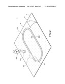
[0017] FIG. 2 is an assembled perspective view showing the first embodiment of the present invention;
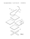
[0018] FIG. 3 is an exploded perspective view showing a second embodiment of the present invention;
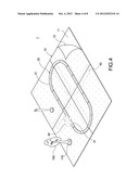
[0019] FIG. 4 is an assembled perspective view showing the second embodiment of the present invention;
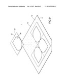
[0020] FIG. 5 is a schematic view showing an arrangement of the track structure of the present invention;
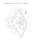
[0021] FIG. 6 is a schematic view showing another arrangement of the track structure of the present invention;
[0022] FIG. 7 is an exploded perspective view showing a third embodiment of the present invention;
[0023] FIG. 8 is an exploded perspective view showing a fourth embodiment of the present invention; and
[0024] FIG. 9 is an assembled perspective view showing the fourth embodiment of the present invention.
DETAILED DESCRIPTION OF THE INVENTION
[0025] The detailed description and technical contents of the present invention will become apparent with the following detailed description accompanied with related drawings. It is noteworthy to point out that the drawings is provided for the illustration purpose only, but not intended for limiting the scope of the present invention.
[0026] Please refer to FIGS. 1 and 2. The present invention relates to an assembled magnetic track structure 1 for a toy vehicle, which includes a base plate 10 and a magnetic track 20.
[0027] The base plate 10 is disposed on the ground (not shown). The base plate 10 is made of an inner iron sheet 11 and an outer pattern layer 12 adhered to the inner iron sheet 11. The outer pattern layer 12 is made of plastic films or cloth adhered to the inner iron sheet 11. A trademark or desired patterns can be printed or stitched on the outer pattern layer 12 of the base plate 10.
[0028] In the embodiment of FIG. 1, the magnetic track 20 is integrally formed by magnetic elements such as rigid or soft magnets. The magnetic track 20 can be magnetically attracted to the inner iron sheet 11 of the base plate 10. The width of the magnetic track 20 is configured to allow two side wheels 31 of a toy vehicle 30 to straddle thereon, so that the toy vehicle 30 can be guided by the magnetic track 20 to run thereon. The thickness and width of the magnetic track 20 can be changed based on practical demands.
[0029] The toy vehicle 30 may be a four-wheeled or multi-wheeled vehicle powered by a spring, an electric motor or solar energy. The wheels 31 on both sides of the toy vehicle 30 run on the magnetic track 20.
[0030] As shown in FIG. 2, since the base plate 10 has the inner iron sheet 11, the user can dispose other decorative elements 100 (such as artificial trees or dolls) on the base plate 10 by means of magnets 110, thereby improving the external appearance, interest and variability of the present invention.
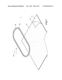
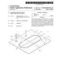
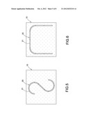
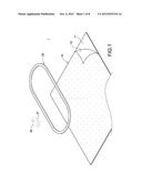
[0031] Please refer to FIGS. 3 to 6, which show the second embodiment of the present invention. The difference between the second embodiment and the first embodiment lies in that: the magnetic track 20 is made by assembling a plurality of magnetic track sections 21 together. Each of the magnetic track sections 21 is magnetically attracted to the base plate 10 to form the track 20. For example, FIG. 4 shows a track of a closed elliptic path. FIG. 5 shows a track of a S-shaped path. FIG. 6 shows a track of an inverted U-shaped path. Of course, the arrangement of the magnetic track sections 21 is not limited to the above, and it may be changed based on practical demands, thereby increasing the interest and variability of the present invention.
[0032] Like the first embodiment, each of the magnetic track sections 21 is made of a magnetic element, which can be magnetically attracted onto the inner iron sheet 11 of the base plate 10.
[0033] The width of the magnetic track section 21 is configured to allow the wheels 31 of the toy vehicle 30 to straddle thereon. The toy vehicle 30 is guided by the track 20 constituted of the magnetic track sections 21. The thickness and the width of each magnetic track section 21 can be changed based on practical demands.
[0034] Please refer to FIG. 7, which shows the third embodiment of the present invention. The difference between the third embodiment and the first embodiment lies in that: a wheel 31' is provided in the center portion of the bottom surface of the toy vehicle 30. An upper surface of the magnetic track 20 is provided with a guiding groove 22 for guiding the wheel 31' to run therein. More specifically, the width of the guiding groove 22 is larger that of the wheel 31' shown in FIG. 7, so that the wheel 31' can be put in the guiding groove 22 and guided thereby. In this way, the toy vehicle 30 can run in the guiding groove 22. Of course, the magnetic track 20 can be provided with a guiding groove 22 no matter it is an integral track shown in FIG. 1 or an assembled track shown in FIG. 3.
[0035] Since the magnetic track sections 21 can be assembled together freely, the user may connect a plurality of base plates 10 together to form a plate of a larger area. As shown in FIG. 3, four base plates 10 are connected together. To this end, magnetic fixing stripes 40 are magnetically attracted to the bottom surfaces of the base plates 10 for fixing the base plates 10 to each other.
[0036] It should be noted that, although the magnetic track section 21 shown in FIGS. 3 to 7 is completely made of a magnetic element, it can be easily though by those skilled in this art that, the magnetic track section 21 may be made of a non-magnetic body (such as paper) and two magnets adhered to both ends of the non-magnetic body. By this structure, the non-magnetic body having two magnets on its both ends can still achieve the same effect as that of the above-mentioned magnetic track section 21. With the two magnets having different magnetic polarities, a plurality of non-magnetic bodies can be connected in series.
[0037] Please refer to FIGS. 8 and 9, which show the fourth embodiment of the present invention. The difference between the fourth embodiment and the third embodiment lies in that: the magnetic track 20' is made by assembling a plurality of magnetic pieces 21' and 22' (or 23' and 24'). The gaps between any two magnetic pieces 21' and 22' are connected to form the magnetic track 20'. Thus, the wheel 31' of the toy vehicle 30 shown in FIG. 7 can also run in the magnetic track 20' formed by the magnetic pieces 21' and 22' or formed by the magnetic pieces 23' and 24'.
[0038] In comparison with prior art, the present invention has the advantageous features as follows.
[0039] The base plate 10 is made of an iron sheet, so that the user can additionally dispose decorative elements 100 on the base plate 10 by magnets 110 to thereby change the background and decoration of the base plate 10. Further, the magnetic track sections 21 are made of magnetic elements such as rigid or soft magnets, so that the magnetic track sections 21 can be magnetically attracted onto the base plate 10 to form the tracks 20 of different paths freely. Further, the magnetic track sections 21 made of magnetic elements can be colored freely, thereby increasing the interest and variability of the present invention. In this way, the user can bring his/her imagination and creativity into full play.
[0040] On the other hand, since the magnetic track sections 21 and the base plate 10 are not made of plastic materials, the manufacturer needs not to design different molds for various kinds of track sections 21 and base plates 10. Thus, the expense of molds and the production cost are saved. Further, the inventory and the selling cost are reduced.
[0041] Although the present invention has been described with reference to the foregoing preferred embodiments, it will be understood that the invention is not limited to the details thereof. Various equivalent variations and modifications can still occur to those skilled in this art in view of the teachings of the present invention. Thus, all such variations and equivalent modifications are also embraced within the scope of the invention as defined in the appended claims.
User Contributions:
Comment about this patent or add new information about this topic:
| People who visited this patent also read: | |
| Patent application number | Title |
|---|---|
| 20140109219 | TRANSITIONING BETWEEN ACCESS STATES OF A COMPUTING DEVICE |
| 20140109218 | PROVISIONAL ADMINISTRATOR PRIVILEGES |
| 20140109217 | APPARATUS AND METHOD FOR UNLOCKING SCREEN AND EXECUTING OPERATION IN A PORTABLE TERMINAL |
| 20140109216 | PORTABLE PERSONAL INFORMATION STORAGE DEVICE |
| 20140109215 | COMPUTER DEVICE CAPABLE OF LOCKING SCREEN AND THE SCREEN LOCKING METHOD THEREOF |
Images included with this patent application:
 |  |
 |  |
 |  |
 |  |
 |
| Similar patent applications: | |
| Date | Title |
|---|---|
| 2012-12-27 | Detachable garment or accessory for a toy |
| 2009-08-13 | Wall racer toy vehicles |
| 2011-11-17 | Wall racer toy vehicles |
| 2012-07-19 | Autotunes music movement toy vehicle |
| 2010-03-25 | Compressible mechanism for toy |
| New patent applications in this class: | |
| Date | Title |
|---|---|
| 2009-02-05 | Apparatus useful as a toy, puzzle or as an educational device |
| New patent applications from these inventors: | |
| Date | Title |
|---|---|
| 2015-08-13 | Fixing structure and electronic device therewith |
| Top Inventors for class "Amusement devices: toys" | |
| Rank | Inventor's name |
|---|---|
| 1 | Robert H. Mimlitch, Iii |
| 2 | David Anthony Norman |
| 3 | Michael Nuttall |
| 4 | Stacy Lynn O'Connor |
| 5 | Joel Reagan Carter |