Patent application title: WIRE BINDING TOOL
Inventors:
Paul Andrade (Kea'Au, HI, US)
Richard E. Gorman (Pahoa, HI, US)
IPC8 Class: AB21F1504FI
USPC Class:
140118
Class name: Joining wire implements twisters
Publication date: 2012-10-04
Patent application number: 20120247609
Abstract:
A wire bonding tool provides an improved and safer grip of wires during
bonding of lengthy wire strands. The tool includes a bar with a polygonal
outer perimeter, a slot in the bar for receiving wire, and a post on an
end face of the bar for receiving a wrapped end of the wire.Claims:
1. A wire binding tool, comprising: a bar; a plurality of lengthwise
faces on the bar arranged in a polygonal perimeter around a center
longitudinal axis of the bar, wherein one of the faces includes spaced
apart walls defining a slot there-between running from a first end of the
bar to a second end of the bar; and a post projecting from the first end
of the bar.
2. The wire binding tool of claim 1 comprising internal slanted surfaces on the spaced apart walls at an entrance to the slot wherein the internal slanted surfaces are arranged in a narrowing V-shape from the entrance.
3. The wire binding tool of claim 2 wherein the one face includes beveled edges at the entrance of the slot on the internal slanted surfaces.
4. The wire binding tool of claim 1 comprising a circular channel positioned at a bottom of the slot.
5. The wire binding tool of claim 4 wherein a bottom of the internal slanted surfaces are spaced from the circular channel.
6. A wire binding tool, comprising: an elongated hexagonal bar; opposing walls defining a slot running lengthwise from opposite ends of the bar; internal slanted surfaces on the opposing walls, wherein the internal slanted surface taper inwardly from an entrance of the slot; and a post projecting from one of the ends of the bar.
7. The wire binding tool of claim 6 comprising beveled edges at the entrance of the slot.
8. The wire binding tool of claim 6 comprising a circular channel positioned at a bottom of the slot, wherein the circular channel extends to at least one of the ends of the bar.
9. The wire binding tool of claim 6 wherein the post is adjustable to extend at different lengths from the end of the bar.
10. The wire binding tool of claim 6 comprising a beveled edge on an end face of the bar at an end of the circular channel.
Description:
CROSS-REFERENCE TO RELATED APPLICATIONS
[0001] This application claims the benefit of priority of U.S. Provisional patent application No. 61/469,238, filed Mar. 30, 2011, which is herein incorporated by reference.
BACKGROUND OF THE INVENTION
[0002] The present invention generally relates to tooling, and more particularly, to a wire binding tool.
[0003] It may be common to bond strands of wire together when a long perimeter or line or wiring is needed. Conventionally, two pieces of wire, for example barbed wire defining a fence line, may be manually held together by one hand while a second hand twists wire ends together with a pair of pliers. Over long distances, this may easily cause fatigue in the hands, particularly the one holding the two wires together. Moreover, when one wire is tensioned because it is secured on another end, the difficulty in bonding it to separate wire increases.
[0004] As can be seen, there is a need for a wire bonding tool that relieves fatigue in the hands and assists in tying two strands of wire together.
SUMMARY OF THE INVENTION
[0005] In one aspect of the present invention, a wire binding tool, comprises a bar; a plurality of lengthwise faces on the bar arranged in a polygonal perimeter around a center longitudinal axis of the bar, wherein one of the faces includes spaced apart walls defining a slot there-between running from a first end of the bar to a second end of the bar; and a post projecting from the first end of the bar.
[0006] In another aspect of the present invention, a wire binding tool comprises an elongated hexagonal bar; opposing walls defining a slot running lengthwise from opposite ends of the bar; internal slanted surfaces on the opposing walls, wherein the internal slanted surface taper inwardly from an entrance of the slot; and a post projecting from one of the ends of the bar.
[0007] These and other features, aspects and advantages of the present invention will become better understood with reference to the following drawings, description and claims.
BRIEF DESCRIPTION OF THE DRAWINGS
[0008] FIG. 1 is an end view of a wire bonding tool according to an exemplary embodiment of the present invention;
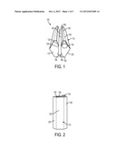
[0009] FIG. 2 is a side view of the wire bonding tool of FIG. 1;
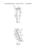
[0010] FIG. 3 is a perspective side view of the wire bonding tool of FIG. 1;
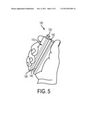
[0011] FIG. 4 is a perspective top view of the wire bonding tool of FIG. 1; and
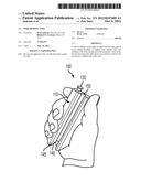
[0012] FIG. 5 is a perspective top view of the wire bonding tool of FIG. 1 held by a user.
DETAILED DESCRIPTION OF THE INVENTION
[0013] The following detailed description is of the best currently contemplated modes of carrying out exemplary embodiments of the invention. The description is not to be taken in a limiting sense, but is made merely for the purpose of illustrating the general principles of the invention, since the scope of the invention is best defined by the appended claims.
[0014] Various inventive features are described below that can each be used independently of one another or in combination with other features.
[0015] Broadly, embodiments of the present invention generally provide a hand tool used to secure, attach, connect, bind and anchor single strand wire in the process of fencing or extension of single strand wiring. Aspects of the wire binding tool may be used to quickly and consistently attach wire in a uniform manner to fixed objects such as fence posts or to affix the wire to another piece of wire for extension purposes such as continuing a fence line when an original wire supply is not long enough.
[0016] Referring now to FIGS. 1-4, a wire bonding tool 100 is shown according to an exemplary embodiment of the present invention. The wire bonding tool 100 may include an elongated bar 110. The bar 110 may be about 1.5'' in diameter and about 4.25'' long. The bar 110 may include one or more outer side faces 125. In an exemplary embodiment, the bar 110 includes a polygonal perimeter, for example, six lengthwise outer side faces 125 arranged as a hexagonal perimeter around the center lengthwise or longitudinal axis of the bar 110. End faces 115 may resemble hexagonal faces when viewed from an end perspective. One of the side faces 125 (for sake of illustration, designated as 125') may include a slot 160 defined by spaced apart opposing walls 135 running the length of the bar 110 from one end face 115 to the other end face 115. The walls 135 may include internal slanted surfaces 140. The internal slanted surfaces 140 may taper inwardly from the entrance in a narrowing V-shape. The walls 135 may include a beveled edge 145 leading into the slanted surfaces 140. A circular channel 150 may be bored along a bottom surface of the slot 160. The circular channel 150 may run lengthwise through the bar 110 from one end face 115 to the other end face 115. The end faces 115 may include a counter-bored bevel 155 at the end of the circular channel 150.
[0017] In an exemplary embodiment, the slated walls 140 may terminate down into the slot 160 above the circular channel 150 so that a section of the walls 135 are parallel to one another. The diameter of the circular channel 150 may be larger than the separation of side walls 135 where they run parallel to one another. For example, the slanted surfaces 140 may be about 7/16'' wide at the slot 160 entrance and gradually taper down to about 1/2'' to 3/8'' in width. The side walls 135 may continue for another 9/16'' in depth at 3/8'' of width running until intersecting with the circular channel 150. The circular channel 150 may have a diameter of approximately 5/16''. The total depth of the slot 160 from side 125' to the bottom surface 165 may be about 13/8'' leaving about 1/8'' to the base (side face 125) of the bar 110.
[0018] A post 130 may project from one or both end faces 115. The post 130 may be positioned proximate the side wall 125'. The post 130 may be a 1/4'' by 7/8'' protrusion such as a hex machine screw threaded into a 3/4'' machine threaded hole (not shown) located approximately 1/8'' from the side 125 closest to the entrance of slot 160. The hole may be evenly spaced between the slot 160 and the side 125. In one aspect, the post 130 is adjustable. When screwed into the threaded hole, a post head may be exposed about 1/8'' out of the threaded hole. However, depending on the gauge of wire being bound, the distance needed to expose the post head from the end face 115 may be adjusted.
[0019] Referring now to FIG. 5, an exemplary operation of the wire bonding tool 100 is shown according to an exemplary embodiment of the present invention. In an exemplary use of the wire bonding tool 110, a piece of wire (not shown) to be secured or bound may be placed lengthwise in the slot 160. The wire may first encounter one of the beveled edges 145, preventing unwanted fraying of the wire, and may be guided by the slanted side walls 140 down into the slot 160. The wire may be slid down the side walls 135 until it is positioned into the circular channel 150 where dislodgement of the wire back up the slot 160 is discouraged by the side walls 135 being barrower than the circular channel 150. An end of the wire may be lead out of the circular channel 150 circularly across the smooth bevel edge 155 and brought up toward the post 130. The cut end of the wire is wrapped around the exposed head of the post 130. A user (not shown) may grasp the tool 100 by wrapping his or her fingers around the hexagonal outer side faces 125. The user may manually twist around the wire to be secured. The wire may be twisted clockwise or counter-clockwise to complete securement. In cases where the wire length is to be extended, a pair of pliers may need to be used in order to stabilize the wire that is being extended until the securing process is complete.
[0020] Typical wire that may be used with the wire binding tool may include hog wire type fencing and other types of single stranded wire. The wire binding tool 100 is a fast and uniform way to wrap each individual wire end to complete the anchoring process of single strand wire fencing. The wire binding tool 100 may also be used to extend or join many other types of wire where a perfect wire loop is desired.
[0021] It should be understood, of course, that the foregoing relates to exemplary embodiments of the invention and that modifications may be made without departing from the spirit and scope of the invention as set forth in the following claims.
User Contributions:
Comment about this patent or add new information about this topic:
Images included with this patent application:
 |  |
 |  |
| Similar patent applications: | |
| Date | Title |
|---|---|
| 2009-04-30 | Wire twisting tool |
| 2009-12-17 | Handheld wire twisting tool |
| 2011-01-27 | Wire untwisting tool |
| 2012-03-08 | Wire twisting tools and methods |
| 2009-03-26 | Tie guide channel for cable tie installation tool |
| Top Inventors for class "Wireworking" | |
| Rank | Inventor's name |
|---|---|
| 1 | Takahiro Nagaoka |
| 2 | Ichiro Kusakari |
| 3 | Osamu Itagaki |
| 4 | Ian David Coles |
| 5 | Edward P. Dyer |