Patent application title: Fluorescent strip light style L.E.D. retrofit wiring methods
Inventors:
Andrew Russell Mellon (Seattle, WA, US)
IPC8 Class: AH01J902FI
USPC Class:
445 2
Class name: Electric lamp or space discharge component or device manufacturing process repairing, converting or salvaging
Publication date: 2012-09-13
Patent application number: 20120231693
Abstract:
The following depictions are of the retrofit wiring of a fluorescent
"strip-light" style fixture for conversion to an LED light. Some of the
drawings depict a fixture for use of a single lamp while others depict
accommodating multiple lamps. The pattern is essentially the same. The
perspective is from inside the fixture looking at the bottoms of the
"tombstones" or lamp holders. Notice that there is no ballast included in
the depictions. The ballast does not necessarily have to be removed
entirely from the fixture, but it may need to be bypassed. There are two
basic options of wiring methods used to make the conversion, one for
increased safety, the other for economy. The multiple depictions
represent the numerous variations of the conversion. FIGS. 1-26 represent
wiring for improved safety. FIGS. 27-38 represent wiring for improved
economy.Claims:
1. A method for utilizing fluorescent strip-light style fixtures for use
with LED lamps.
2. Improving the safety of retrofitting a fluorescent strip-light fixture for use of LED lamps, whereby keeping the positive and neutral terminals at opposing ends.
3. Improving the economy of retrofitting a fluorescent strip-light fixture for use of LED lamps, whereby keeping the positive and neutral terminals on the same end of the fixture.
Description:
DESCRIPTION OF THE DRAWINGS
[0001] Methods for retrofitting or converting a fluorescent fixture for use of LED lamp(s) [Ref app. #13/343,003 Jan. 4, 2012, provisional patent #61/416,691 Nov. 23, 2010]
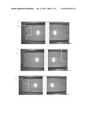
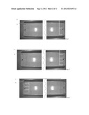
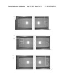
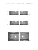
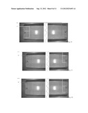
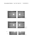
Option 1: Method of Wiring for Increased Safety. (FIG. 1-26)
[0002] Disconnect fixture from any source of power. Gain access to the wiring of the fixture by removing any backing or ballast cover. Once the wiring is exposed, note the termination of each wire into the "tombstones" (or lamp holders). The lamp holders may be located on opposing sides of the fixture. We shall call these sides left (L) and right (R) as the orientation would appear from retrofitter if they were positioned at the middle of the fixture. The ballast may need to be removed or bypassed. Do so by physically cutting the wires and removing the ballast or bypassing the ballast, properly terminating the wires as necessary. Next, take the wires terminating at the lamp holders on the (L) side and connect them to one of the "poles" either Positive or Neutral. Then, take the wires terminating at the lamp holders from the (R) side and connect them to the remaining "pole". Check all wires for proper termination and the ground wire (if available) for proper grounding. Replace the backing or ballast cover. Indicate that the fixture has been modified for LED usage on the exterior of the fixture.
[0003] Advantage: By keeping the terminating poles on opposing sides of the fixture, there are less chances of incident (such as arching, shorting). Disadvantage: Extra materials may be needed to make the connection from the side opposite the "Input" side.
[0004] FIG. 1 shows wiring using method for improved safety. Color red=positive and yellow=neutral
[0005] FIG. 2 shows wiring using method for improved safety. Color red=positive and yellow=neutral
[0006] FIG. 3 shows wiring using method for improved safety. Color red=positive and yellow=neutral
[0007] FIG. 4 shows wiring using method for improved safety. Color red=positive and yellow=neutral
[0008] FIG. 5 shows wiring using method for improved safety. Color red=positive and yellow=neutral
[0009] FIG. 6 shows wiring using method for improved safety. Color red=positive and yellow=neutral
[0010] FIG. 7 shows wiring using method for improved safety. Color red=positive and yellow=neutral
[0011] FIG. 8 shows wiring using method for improved safety. Color red=positive and yellow=neutral
[0012] FIG. 9 shows wiring using method for improved safety. Color red=positive and yellow=neutral
[0013] FIG. 10 shows wiring using method for improved safety. Color red=positive and yellow=neutral
[0014] FIG. 11 shows wiring using method for improved safety. Color red=positive and yellow=neutral
[0015] FIG. 12 shows wiring using method for improved safety. Color red=positive and yellow=neutral
[0016] FIG. 13 shows wiring using method for improved safety. Color red=positive and yellow=neutral
[0017] FIG. 14 shows wiring using method for improved safety. Color red=positive and yellow=neutral
[0018] FIG. 15 shows wiring using method for improved safety. Color red=positive and yellow=neutral
[0019] FIG. 16 shows wiring using method for improved safety. Color red=positive and yellow=neutral
[0020] FIG. 17 shows wiring using method for improved safety. Color red=positive and yellow=neutral
[0021] FIG. 18 shows wiring using method for improved safety. Color red=positive and yellow=neutral
[0022] FIG. 19 shows wiring using method for improved safety. Color red=positive and yellow=neutral
[0023] FIG. 20 shows wiring using method for improved safety. Color red=positive and yellow=neutral
[0024] FIG. 21 shows wiring using method for improved safety. Color red=positive and yellow=neutral
[0025] FIG. 22 shows wiring using method for improved safety. Color red=positive and yellow=neutral
[0026] FIG. 23 shows wiring using method for improved safety. Color red=positive and yellow=neutral
[0027] FIG. 24 shows wiring using method for improved safety. Color red=positive and yellow=neutral
[0028] FIG. 25 shows wiring using method for improved safety. Color red=positive and yellow=neutral
[0029] FIG. 26 shows wiring using method for improved safety. Color red=positive and yellow=neutral
DESCRIPTION OF THE DRAWINGS
[0030] Methods for retrofitting or converting a fluorescent fixture for use of LED lamp(s) [Ref app. #13/343,003 Jan. 4, 2012, provisional patent #61/416,691 Nov. 23, 2010]
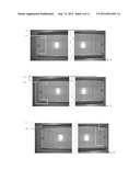
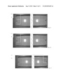
Option 2: Method of Wiring for Best Economy. (FIG. 27-33)
[0031] Disconnect fixture from any source of power. Gain access to the wiring of the fixture by removing any backing or ballast cover. Once the wiring is exposed, note the termination of each wire into the "tombstones" (or lamp holders). The lamp holders may be located on opposing sides of the fixture. Find the "Input" side of the fixture (or the side where the positive and neutral input wires exist). Remove all wiring and ballast(s) except for the wiring that terminates at the "tombstones" (lamp holders) at the "Input" side of the fixture. Now, there is only wiring at the "Input" side of the fixture, terminating at the lamp holders. Of these wires, there must be at least 1 wire per each side of 1 lamp holder. We shall call these sides (of each lamp holder) left (L) and right (R). Symmetry is recommended, so take the (L) side wires of each lamp holder and terminate at the "Input" pole (choose one, either positive or neutral). Then, connect the wires on the (R) side of each lamp holder and connect to the remaining pole. Only the "Input" side of the fixture should have wires terminating at the lamp holders of the "Input" side. The opposing end lamp holders should be "dead" and terminated properly. Check all wires for proper termination and the ground wire (if available) for proper grounding. Replace the backing or ballast cover. Indicate that the fixture has been modified for LED usage on the exterior of the fixture.
[0032] Advantages: This method uses less time and materials as the wiring in the "tombstones" (lamp holders) of the "Input" side should already be in place. They simply need to correspond with the correct pole. It is possible that no additional wire will be necessary. Disadvantage: By having the positive and neutral poles terminate at the same "tombstone" (lamp holder), there exists greater chance of incident (i.e. arcing, shorting).
[0033] FIG. 27 shows wiring using method for improved economy. Color red=positive and yellow=neutral
[0034] FIG. 28 shows wiring using method for improved economy. Color red=positive and yellow=neutral
[0035] FIG. 29 shows wiring using method for improved economy. Color red=positive and yellow=neutral
[0036] FIG. 30 shows wiring using method for improved economy. Color red=positive and yellow=neutral
[0037] FIG. 31 shows wiring using method for improved economy. Color red=positive and yellow=neutral
[0038] FIG. 32 shows wiring using method for improved economy. Color red=positive and yellow=neutral
[0039] FIG. 33 shows wiring using method for improved economy. Color red=positive and yellow=neutral
User Contributions:
Comment about this patent or add new information about this topic:
| People who visited this patent also read: | |
| Patent application number | Title |
|---|---|
| 20120230327 | TERMINAL APPARATUS FOR TRANSMITTING OR RECEIVING A SIGNAL INCLUDING PREDETERMINED INFORMATION |
| 20120230326 | BIOLOGICAL DATA NETWORKS AND METHODS THEREFOR |
| 20120230325 | FORWARDING INTER-SWITCH CONNECTION (ISC) FRAMES IN A NETWORK-TO-NETWORK INTERCONNECT TOPOLOGY |
| 20120230324 | Method and Apparatus for Identifying VoIP Traffic |
| 20120230323 | Smart Routing for Voice Over Internet Protocol |
Images included with this patent application:
 |  |
 |  |
 |  |
 |  |
| New patent applications in this class: | |
| Date | Title |
|---|---|
| 2015-10-29 | Polarizer removing device and method of using it |
| 2015-01-29 | Method of constructing a new type of spark plug |
| 2014-09-11 | Systems and methods for providing polarization compensated multi-spectral laser repair of liquid crystal display panels |
| 2014-07-24 | Method for repairing white defect of liquid crystal display panel |
| 2014-07-17 | Apparatus and method for repairing array substrate |
| Top Inventors for class "Electric lamp or space discharge component or device manufacturing" | |
| Rank | Inventor's name |
|---|---|
| 1 | Shou-Shan Fan |
| 2 | Peng Liu |
| 3 | Kai-Li Jiang |
| 4 | Liang Liu |
| 5 | Yang Wei |