Patent application title: Concealed Carry Garment
Inventors:
Andrew Reynolds (Grove City, OH, US)
IPC8 Class: AA41D100FI
USPC Class:
2 69
Class name: Apparel body garments
Publication date: 2012-09-13
Patent application number: 20120227152
Abstract:
A garment adapted for concealed carry weapons users wherein a passageway
within or upon the garment is adapted to receive a flexible cord. The
passageway extends from an opening on an upper exterior of the garment to
a lower section of the garment. The cord is attached at an end of the
passageway at the lower section and extends through the passageway,
through the opening, and to a second attachment point at a removable
piece. The removable piece releasably attachable to the garment. When
worn, to gain access to a weapon under the garment, the user grasps the
removable piece and pulls it away from the garment, raising the lower
section of the garment and allowing access to the weapon. When the
removable piece is replaced, the lower section lowers to its original
position.Claims:
1. A garment comprising: a concealed passageway within or upon the
garment adapted to receive a flexible cord, the passageway extending from
an opening on an upper exterior of the garment to a lower section of the
garment; the cord attached at an end of the passageway at the lower
section and extending through the passageway, through the opening, and to
a second attachment point at a removable piece; the removable piece
releasably attachable to the garment.
2. The garment of claim 1 wherein the removable piece is an item that normally appears on garments selected from the group an epaulette, a shoulder tab, a button, an artificial flower, a handkerchief, a piece of jewelry, a collar and a lapel.
3. The garment of claim 1 wherein the removable piece is removeably attached by a fastener selected from at least one of a snap, a tab, a clip, a hook and a hook and loop-type fastener.
4. The garment of claim 1 wherein the garment is a shirt and the removable piece is a shoulder tab.
5. The garment of claim 1 wherein the lower section of the garment is a bottom of the garment at a side seam.
6. The garment of claim 1 wherein the removable piece is located on a left side of the garment.
7. The garment of claim 1 wherein the removable piece is located on a right side of the garment.
8. The garment of claim 1 comprising two passageways, a first passageway extending from a lower section of the garment at a bottom of the garment at first side seam, and a second passageway extending from the bottom of the garment at a second side seam, each passageway enclosing a cord, a first cord attached to a first removable piece on a left side of the garment and a second cord attached to a second removable piece on a right side of the garment.
9. A method of providing access to a concealed weapon worn on a user's belt comprising the steps of: a) donning a garment, the garment comprising a replaceable removable piece located on an exterior of the garment, said removable piece attached to a cord, said cord concealed within the garment and attached at an opposite end to a lower section of the garment, said lower section proximate to the concealed weapon covered by the garment; b) grasping the removable piece; and c) pulling the removable piece in a direction away from the garment; whereby when the cord attached to the lower section of the garment is pulled, the lower section is raised and allows access to the weapon.
10. The method of claim 9 wherein the user replaces the removable piece and the lower section lowers to its original position.
Description:
CROSS-REFERENCES TO RELATED APPLICATIONS
[0001] This patent application is a continuation in part of patent application Ser. No. 13/046,128 ("Yank and Draw Concealed Carry Garment") filed Mar. 11, 2011, hereby incorporated by reference.
BACKGROUND OF THE INVENTION
[0002] The present invention relates to improvements in apparel worn by licensed concealed carry weapons users and allows a quick, easy and unobstructed weapons draw when a user is wearing the garment described herein.
[0003] In the prior art concealed carry handgun pistol holsters and carriers are known. However, when a weapon such as a handgun is covered or concealed by an outer garment, quick access to the concealed weapon may be hindered as an outer garment may obstruct removal of the handgun from its holster or carrier location when quick access to the weapon is necessary.
[0004] There are several ways of drawing a weapon from under a concealment garment. First, when wearing a pullover garment: You reach over with your support side hand, grab hold of the bottom edge of the garment under the weapon and pull the garment up and over the weapon. Because of a person's size, agility or lack of practice, this method can be impossible or too slow. Second, when an open or unsecured vest is worn, the draw involves using the hand that you are drawing the weapon with, cupping your fingers over the front opening of the garment and sweeping the side of the garment back far enough to get a good grip on the weapon. In this instance, the front of the garment must be open or able to be opened quickly. It also takes a lot of practice to become proficient.
SUMMARY OF THE INVENTION
[0005] The present invention is directed to overcoming the problems set forth above. It is an object of the present invention to facilitate a quick draw of a weapon when a holstered handgun is covered by a garment, namely, to unencumber access to the weapon concealed by a garment. The present invention is a garment comprising a concealed passageway within or upon the garment adapted to receive a flexible cord. The passageway extends from an opening on an upper exterior of the garment to a lower section of the garment. The cord is attached at an end of the passageway at the lower section and extends through the passageway, through the opening, and to a second attachment point at a removable piece. The removable piece is releasably attachable to the garment. The removable piece is an item that normally appears on garments, such as but not limited to an epaulette, a shoulder tab, a button, an artificial flower, a handkerchief, a piece of jewelry, a collar, a lapel, and the like. The removable piece is removeably attached by a fastener, such as but not limited to a snap, a tab, a clip, a hook, a hook and loop-type fastener, and the like. The lower section of the garment is a bottom of the garment at a side seam. The removable piece may be located on the left or right side of the garment, or the garment may have two passageways, with a first passageway extending from a lower section of the garment at a bottom of the garment at first side seam, and a second passageway extending from the bottom of the garment at a second side seam. Each passageway encloses a cord attached individual removable pieces. In an embodiment, the garment is a shirt and the removable piece is a shoulder tab.
[0006] A user uses the garment to access to a concealed weapon worn on his/her belt by: a) donning the garment with a concealed weapon covered by the garment; b) grasping the removable piece; and c) pulling the removable piece in a direction away from the garment. The pulling movement raises the lower section and allows access to the weapon. When the user wants to release the pulled lower section, he/she replaces the removable piece and the lower section lowers to its original position.
[0007] As used herein, "approximately" means within plus or minus 25% of the term it qualifies. The term "about" means between 1/2 and 2 times the term it qualifies.
[0008] The compositions and methods of the present invention can comprise, consist of, or consist essentially of the essential elements and limitations of the invention described herein, as well as any additional or optional ingredients, components, or limitations described herein or otherwise useful in compositions and methods of the general type as described herein.
[0009] Numerical ranges as used herein are intended to include every number and subset of numbers contained within that range, whether specifically disclosed or not. Further, these numerical ranges should be construed as providing support for a claim directed to any number or subset of numbers in that range or to be limited to the exact conversion to a different measuring system, such, but not limited to, as between inches and millimeters.
[0010] All references to singular characteristics or limitations of the present invention shall include the corresponding plural characteristic or limitation, and vice versa, unless otherwise specified or clearly implied to the contrary by the context in which the reference is made.
[0011] All combinations of method or process steps as used herein can be performed in any order, unless otherwise specified or clearly implied to the contrary by the context in which the referenced combination is made.
[0012] Terms such as "top," "bottom," "right," "left," "above", "under", "side" "front" and "back" and the like, are words of convenience and are not to be construed as limiting.
[0013] These and other aspects, objects, features and advantages of the present invention will be more clearly understood and appreciated from a review of the following detailed description of the preferred embodiments and appended claims, and by reference to the accompanying drawings.
BRIEF DESCRIPTION OF THE SEVERAL VIEWS OF THE DRAWING
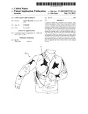
[0014] FIG. 1 is a front perspective view of an embodiment of the invention.
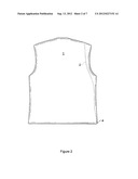
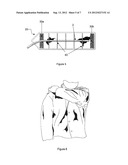
[0015] FIG. 2 is a back view of an embodiment of the body of the invention.
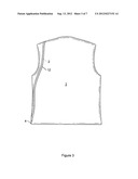
[0016] FIG. 3 is an inside view of an embodiment of the body of the invention with a single layer of material.
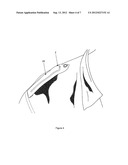
[0017] FIG. 4 is a detail perspective showing cord placement in an epaulette.
[0018] FIG. 5 is a bottom view of an epaulette showing cord placement.
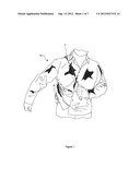
[0019] FIG. 6 is a perspective view of a garment n a user being activated.
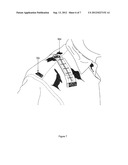
[0020] FIG. 7 is a perspective view of an epaulette removed from the shoulder fastener.
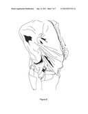
[0021] FIG. 8 is a perspective side view of a garment on a user with the garment activated, the pull cord fully extended, and the garment raised to expose the weapon and holster.
DETAILED DESCRIPTION OF THE INVENTION
[0022] Reference will now be made in detail to the exemplary embodiments of the invention, examples of which are illustrated in the accompanying drawings. As shown in FIG. 1, the invention is an upper torso garment that allows a user of a concealed carry weapon a quick, easy and unobstructed weapon draw. The garment includes a passageway or tunnel within or upon the garment adapted to receive a longitudinally extending flexible cord or lanyard. The passageway extends from the shoulder of the garment to a lower section of the garment body. The cord extends outside the garment from an opening in the passageway at the shoulder where it is reachable by the user. The lower end of the pull is secured to the garment at a location on the garment proximate a concealed weapon carried by the wearer beneath the garment. The terminal exterior section of the cord is concealed in a removable piece. The removable piece is preferably something that would normally appear on a garment, such as but not limited to, an epaulette or shoulder tab that extends inward from the sleeve seam and terminates typically with a button, at the edge of the collar, an artificial flower, a handkerchief in a pocket, a piece of jewelry, a collar or lapel, and the like. When the user pulls the removable piece downward, the cord pulls the lower section upward, raising the garment and allowing unimpeded access to the otherwise concealed weapon.
[0023] In variations, the garment can be made of multiple layers of material (e.g., a textile materials, leather, polymeric materials, nylon webbing, vinyl or other garment material or any other suitable material that is strong and flexible) forming the garment wherein a passageway is created between two of the layers. In another variation, the passageway may comprise a tunnel adapted to receive the pull wherein the tunnel is affixed to a layer of material forming the garment, or the tunnel may be affixed to the exterior of the garment, or configured in the interior of the garment.
[0024] Referring to the embodiment depicted in FIG. 1, the garment 10 is shown as a shirt, but any garment, such as a vest, coat, shawl, jacket, or any article of clothing that would conceal a weapon and provide an area to place a piece to act as an end for a pull cord can be used. Cord 2 is any strong, flexible cord, wire, rope, can be braided or twisted, and is secured (by stapling, sewing, heat bonding and the like) to the inside bottom of the side seam of the body 1 as indicated at 4 (see FIG. 2). In an embodiment, the cord 2 is parachute cord. The cord is positioned depending on which side a person wears a weapon (left side is a mirror image of the right). In an embodiment, the garment comprises a cord on each side of the garment.
[0025] As shown in FIG. 3, the body of the garment includes a tunnel 12. In an embodiment having a single layer of material at the body, the tunnel is formed from a strip material. The strip is sewn or attached to the body on both side edges to form the tunnel. In an embodiment, a one inch strip of material is attached from the lower side seam to an opening in the shoulder, which may be finished with an eyelet having a size, for example, about 1/4 inch inside diameter. When each side of the length of the strip is sewn from the lower seam to the eyelet, a tunnel pathway for the cord to run through is formed. In an embodiment, the body of the garment comprises two layers of material sewn together to form the tunnel 12 with enough space for cord to be able to move freely through it. The tunnel keeps the cord in proper placement so it will not slip down over the shoulder or be tangled in movement. The tunnel 12, within which the cord is located, extends from an opening in the shoulder to a bottom seam 4 of the garment.
[0026] Referring to an embodiment depicted in FIG. 4, the cord 2 exits the body 1 at the shoulder under the removable piece 20. The cord 2 exits from the body 1 and is attached to and concealed in or under the removable piece 20. In an embodiment depicted in FIG. 5, the cord 2 is fixed at various points to an epaulette on the bottom side. In an embodiment, the cord is fixed between two pieces of cloth that form the epaulette. The end of the cord (opposite the end fixed at the bottom section) is firmly attached to the removable piece. In an embodiment, the removable piece comprises pieces 40 to add stability and prevent tearing, etc.
[0027] As shown in FIG. 6, in an embodiment using an epaulette, a user grasps the epaulette and pulls it down, which pulls the cord 2. The cord pulls the bottom edge of the body of the garment up, revealing a weapon carried on the user's belt. As depicted in FIG. 7, the removable piece is removeably attached to the body by any known fastening means 30a,b,c,d, such as snaps, tabs, clips, hooks or a hook and loop-type fastener attached to the removable piece and the body. "Hook and loop-type" means of the type employed in separable fasteners that are marketed by Velcro USA, Inc., 406 Brown Avenue, Manchester, N.H., under the trademarks VELCRO® hook and loop fasteners, and VELCRO STICKY BACK® strips of hook and loop fasteners with adhesive backing type of VELCRO® brand tape which has a peel-off backing. The tape is also sold under the STICKY BACK® brand name.
[0028] FIG. 8 depicts a user removing a concealed weapon as the garment has been deployed. The invention includes accommodations for left-handed or persons that can use either hand as well.
[0029] The foregoing descriptions of specific embodiments and examples of the present invention have been presented for purposes of illustration and description. They are not intended to be exhaustive or to limit the invention to the precise forms disclosed, and obviously many modifications and variations are possible in light of the above teachings. It will be understood that the invention is intended to cover alternatives, modifications and equivalents. The embodiments were chosen and described in order to best explain the principles of the invention and its practical application, to thereby enable others skilled in the art to best utilize the invention and various embodiments with various modifications as are suited to the particular use contemplated. It is therefore to be understood that within the scope of the appended claims, the invention may be practiced otherwise than as specifically described herein.
User Contributions:
Comment about this patent or add new information about this topic:
Images included with this patent application:
 |  |
 |  |
 |  |
 |  |
| Similar patent applications: | |
| Date | Title |
|---|---|
| 2012-09-13 | Yank and draw concealed carry garment |
| 2012-04-05 | Convertible scarf garment |
| 2011-01-20 | Breast cancer recovery garment |
| 2012-02-09 | Anti-microbial medical garments |
| 2012-05-17 | Antimicrobial medical garment |
| New patent applications in this class: | |
| Date | Title |
|---|---|
| 2022-05-05 | Garment with directional indicia for visualizing and remembering a coordinated movement of body segments |
| 2019-05-16 | Aerodynamic garment with applied edge treatments |
| 2019-05-16 | Garment having targeted non-slip regions |
| 2018-01-25 | Garment |
| 2018-01-25 | Multipurpose garment |
| Top Inventors for class "Apparel" | |
| Rank | Inventor's name |
|---|---|
| 1 | William L. Grilliot |
| 2 | Mary I. Grilliot |
| 3 | David Turner |
| 4 | Patricia K. Waters |
| 5 | Caleb Clark Crye |