Patent application title: INJECTOR MOUNT AND EXHAUST LINE HAVING AN INJECTOR MOUNT
Inventors:
Jan Hodgson (Troisdorf, DE)
Sven Schepers (Troisdorf, DE)
Sven Schepers (Troisdorf, DE)
Assignees:
EMITEC GESELLSCHAFT FUER EMISSIONSTECHNOLOGIE MBH
IPC8 Class:
USPC Class:
60295
Class name: Internal combustion engine with treatment or handling of exhaust gas by means producing a chemical reaction of a component of the exhaust gas having means for regenerating, replacing, or feeding liquid or solid reagent or catalyst
Publication date: 2012-09-06
Patent application number: 20120222409
Abstract:
An injector mount for completely accommodating at least one injector
includes a housing having at least one injector chamber. The at least one
injector chamber has a first opening and a second opening. The first
opening of the injector chamber can be connected to a region of an
exhaust line that conducts exhaust gas, and the second opening of the
injector chamber can be closed repeatedly by a closure. An exhaust line
having an injector mount is also provided.Claims:
1. An injector mount, comprising: a housing having at least one injector
chamber configured for completely accommodating at least one injector;
said at least one injector chamber having a first opening and a second
opening; said first opening of said at least one injector chamber
configured to be connected to an exhaust-carrying region of an exhaust
line; and a closure configured to close said second opening of said at
least one injector chamber.
2. The injector mount according to claim 1, wherein said closure is configured to be closed in a repeatable manner.
3. The injector mount according to claim 1, which further comprises a first seal and a second seal configured for supporting an injector in said at least one injector chamber.
4. The injector mount according to claim 3, wherein said first seal is a radially acting seal composed at least partially of mica.
5. The injector mount according to claim 1, wherein said at least one injector chamber has at least one aperture in said housing.
6. The injector mount according to claim 1, which further comprises at least one radiation collar.
7. The injector mount according to claim 1, which further comprises at least one supply line leading into said at least one injector chamber.
8. The injector mount according to claim 1, which further comprises at least one control line leading into said at least one injector chamber.
9. The injector mount according to claim 7, wherein said at least one supply line leads into said at least one injector chamber through said closure.
10. The injector mount according to claim 8, wherein said at least one control line leads into said at least one injector chamber through said closure.
11. The injector mount according to claim 1, wherein said closure has at least one connector holder.
12. An exhaust line, comprising: a connecting element fixed at the exhaust line; and an injector mount according to claim 1 releasably connected to said connecting element.
Description:
CROSS-REFERENCE TO RELATED APPLICATION
[0001] This is a continuation, under 35 U.S.C. §120, of co-pending International Application No. PCT/EP2010/062071, filed Aug. 18, 2010, which designated the United States; this application also claims the priority, under 35 U.S.C. §119, of German Patent Application DE 10 2009 048 514.7, filed Oct. 7, 2009; the prior applications are herewith incorporated by reference in their entirety.
BACKGROUND OF THE INVENTION
[0002] 1. Field of the Invention:
[0003] The present invention relates to an injector mount for accommodating an injector. Such injectors can be used, in particular, to add a reducing agent to an exhaust system. The invention also relates to an exhaust line having an injector mount.
[0004] The practice of reducing the nitrogen oxide content of the exhaust gas from an internal combustion engine by selective catalytic reduction (SCR) is known. In that process, a substance with a directly reductive action, such as ammonia or a precursor thereof, is fed into the exhaust gas. One example of a precursor that can be used is an aqueous urea solution. During selective catalytic reduction, ammonia is converted with nitrogen monoxide and nitrogen dioxide to molecular nitrogen and water. Selective catalytic reduction takes place in an SCR catalytic converter.
[0005] Reducing agent is introduced into the exhaust gas through the use of an injector. As a rule, the injector has a fastening device, with the aid of which the injector is fastened on an exhaust line. The injector thus sprays the reducing agent directly into the exhaust line. As a rule, the injector is exposed to high thermal and mechanical stresses, and it must therefore be replaced when damaged. However, it is generally not possible to replace the injector in a simple and economical manner.
SUMMARY OF THE INVENTION
[0006] It is accordingly an object of the invention to provide an injector mount and an exhaust line having an injector mount, which overcome the hereinafore-mentioned disadvantages and at least partially solve the highlighted problems of the heretofore-known devices of this general type. In particular, the object is to provide an injector mount which reduces thermal and mechanical loads on the injector and enables the injector to be changed in a simple and economical manner and to provide an exhaust line which enables an injector to be attached to an injector mount in a particularly simple manner.
[0007] With the foregoing and other objects in view there is provided, in accordance with the invention, an injector mount, comprising a housing having at least one injector chamber configured for completely accommodating at least one injector, the at least one injector chamber having a first opening and a second opening, the first opening of the at least one injector chamber configured to be connected to an exhaust-carrying region of an exhaust line, and a closure configured to close the second opening of the at least one injector chamber.
[0008] The housing is, in particular, a metallic body, which preferably is formed of a tubular hollow profile. However, other forms of housing are nevertheless also possible if this enables an injector to be accommodated completely in an injector chamber. The housing has a length which extends along a central axis or (in the case of a tubular housing) along a center line. In the case of a tubular housing, the length furthermore extends from a first front face of the housing to a second front face of the housing. The length is no more than 20 cm, preferably no more than 15 cm, and particularly preferably no more than 10 cm. The housing furthermore has a width or (in the case of a tubular housing) a diameter which extends orthogonally with respect to the length (or central axis or center line) and which is no more than 10 cm, preferably no more than 5 cm, and particularly preferably no more than 2.5 cm. The housing of the injector mount furthermore has at least one injector chamber, which is a cavity in which at least one injector can be completely disposed. "Completely" means, in particular, that the injector does not protrude beyond an outer boundary of the housing (e.g. the openings) of the injector mount at any point. The injector is formed at least of an injector housing having a reducing agent feed, a nozzle and a valve for controlling a reducing agent discharge by the injector. Moreover, the injector can also have a connection for control signals of an SCR controller.
[0009] The first opening of the injector chamber is disposed and configured in such a way that a reducing agent can be introduced into an exhaust line by the injector. In particular, the first opening is in alignment with a nozzle of the injector and, especially in the case of a tubular housing, is situated in the region of a first front face of the housing. The second opening of the injector chamber is furthermore disposed and configured in such a way that the injector is easily replaceable and/or accessible. For this purpose, the second opening is preferably situated opposite the first opening, in particular in the region of a second front face of the housing. The second opening can furthermore be closed by a closure, wherein the second opening is preferably closed during an operational state of the injector and opened during the maintenance of the injector. The closure can be fastened on the housing of the injector mount by known measures, in particular through the use of a crimped joint.
[0010] In accordance with another feature of the invention, the closure can be closed repeatably. In order to obtain the possibility of a repeatable closing of the second opening, the closure can, in particular, be screwed to the housing of the injector mount in the region of the second opening. For this purpose, the housing has an appropriate thread in the region of the second opening and of the closure. However, the second opening of the injector chamber can also be fastened on the housing of the injector mount by clamping the closure or through the use of a bayonet fastening on the closure.
[0011] In accordance with a further feature of the invention, an injector which is disposed in the at least one injector chamber is supported in the injector chamber through the use of a first seal and through the use of a second seal.
[0012] The injector is supported in the injector chamber by the first seal and by the second seal in such a way that the injector is vibrationally damped or even vibrationally decoupled with respect to the housing of the injector mount. For this purpose, the injector is supported, in particular supported at a distance from the housing, with the aid of the first seal and the second seal. It is thereby possible to achieve an effective reduction in the mechanical loads, in particular vibrational loads, and/or thermal loads acting on the injector. The second seal is, in particular, an O-ring made of rubber.
[0013] In accordance with an added feature of the invention, the first seal is a radially acting seal, which is composed at least partially of rubber or at least partially of mica. In particular, the first seal is suitable for sealing off the injector chamber (together with the injector) from an exhaust-carrying region of an exhaust line. "Mica" is an aluminosilicate. Aluminosilicates are minerals in which silicon is surrounded by four oxygen atoms in a tetrahedral configuration.
[0014] In accordance with an additional feature of the invention, the second seal is composed at least partially of rubber or at least partially of mica. In this context, rubber has proven to have a particularly good vibration damping effect and mica has proven to be particularly heat resistant.
[0015] In accordance with yet another particularly preferred optional feature of the invention, the first seal is formed (exclusively) with mica and the second seal is formed (exclusively) with rubber.
[0016] In accordance with yet a further feature of the invention, the injector chamber has at least one aperture, preferably a plurality of apertures, in the housing. These apertures start from the injector chamber and preferably extend completely through the housing of the injector mount. At the same time, the apertures are preferably distributed radially (and uniformly), in particular over 360°, over a circumferential surface of the housing. It has surprisingly been found that noise caused by vibration and/or noise caused by the injector can be reduced by such apertures. Moreover, pressure equalization between the injector chamber and the surroundings can take place through these apertures when the injector is in the operational state, that is to say, in particular, when the injector mount is connected to an exhaust line through the first opening and the second opening is closed by the closure, if the injector chamber heats up during the operation of the injector.
[0017] In accordance with yet an added particularly advantageous feature of the invention, the injector mount has at least one radiation collar. This at least one radiation collar is disposed radially on the circumferential surface of the housing of the injector mount and is formed of a thermally conductive material, in particular metal. It is thereby possible, on one hand, to achieve cooling of the housing of the injector mount and, on the other hand, to protect connection lines of the injector from heat radiation from the injector mount and/or exhaust line.
[0018] In accordance with yet an additional advantageous feature of the invention, at least one supply line or at least one control line leads into the injector chamber. The supply line is preferably a line which carries a reducing agent from a reducing agent reservoir to the injector and/or vice versa. The control line is preferably an electric lead which connects the injector to a control device of an SCR system for data transmission and/or electrically.
[0019] In accordance with again another expedient feature of the invention, the closure has at least one connector holder. This is, for example, a clamping device which secures against slipping of a connector that fastens the supply line and/or control line on the closure. In this case, the connector is preferably seated on a supply connection of the closure and/or a control connection of the closure. The supply connection of the closure and the control connection of the closure serve to connect the supply line and/or control line to the injector disposed in the injector chamber.
[0020] With the objects of the invention in view, there is concomitantly provided an exhaust line, comprising a connecting element fixed at the exhaust line, and an injector mount according to the invention releasably connected to the connecting element.
[0021] The connecting element is, in particular, a sleeve, a nut or some other element suitable for accommodating an injector mount, wherein the connecting element is, in particular, fixed on the exhaust line through the use of a welded joint. An injector mount is connected releasably, through the use of a screwed joint for example, to this connecting element.
[0022] Other features which are considered as characteristic for the invention are set forth in the appended claims, noting that the features presented individually in the dependent claims can be combined in any technologically meaningful way and define additional embodiments of the invention.
[0023] Although the invention is illustrated and described herein as embodied in an injector mount and an exhaust line having an injector mount, it is nevertheless not intended to be limited to the details shown, since various modifications and structural changes may be made therein without departing from the spirit of the invention and within the scope and range of equivalents of the claims.
[0024] The construction and method of operation of the invention, however, together with additional objects and advantages thereof will be best understood from the following description of specific embodiments when read in connection with the accompanying drawings.
BRIEF DESCRIPTION OF THE SINGLE VIEW OF THE DRAWING
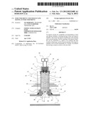
[0025] The figure of the drawing is a longitudinal-sectional view of an exhaust line having an injector mount.
DETAILED DESCRIPTION OF THE INVENTION
[0026] Referring now in detail to the single figure of the drawing, there is seen an exhaust line 8 having an outer wall 27 to which a connecting element 7 is attached through the use of a welded joint 11. This connecting element 7 has a receptacle 28 for an injector mount 1. The receptacle 28 of the connecting element 7 can have a non-illustrated thread for this purpose. The diameter of the receptacle 28 corresponds substantially to the width 22 of the housing 20 of the injector mount 1. In this embodiment, the housing 20 has a tubular construction. The housing 20 of the injector mount 1 furthermore has a length 21 which extends from a first opening 2 to a second opening 3, or from a first front face 24 to a second front face 25, in the direction of a central axis 23 which is illustrated herein as a center line. Within the housing 20 there is an injector chamber 9. This injector chamber 9 is connected at the first opening 2 to an exhaust-carrying region 12 of the exhaust line 8. The second opening 3 is closed in a repeatable manner through the use of a closure 6. The housing 20 and the closure 6 have a non-illustrated thread for this purpose. An injector 10 is supported in the injector chamber 9 through the use of a first seal 4 and a second seal 5 in such a way that a nozzle 32 of the injector 10 is in alignment with the first opening 2 of the housing 20. The first seal 4, together with the injector 10, seals off the injector chamber 9 from the exhaust-carrying region 12 of the exhaust line 8. The injector 10 has an injector housing 33 and a valve 34, which is connected to an SCR controller 31, although the connection of the valve 34 to the SCR controller 31 is not shown herein.
[0027] In addition, the closure 6 has a supply connection 18 and a control connection 19. A supply line 15 and a control line 16 are connected to the injector 10 through the supply connection 18 and the control connection 19 and through the use of a connector 29. In this configuration, the supply line 15 is connected to a reducing agent reservoir 30 and the control line 16 is connected to the SCR controller 31. The closure 6 furthermore has a connector holder 17 for securing the connector 29 against slipping.
[0028] The housing 20 of the injector mount 1 has a plurality of radially disposed apertures 13, which extend from the injector chamber 9 to a circumferential surface 26 of the housing 20. Moreover, a plurality of radiation collars 14 are disposed on the circumferential surface 26 of the housing 20.
[0029] Starting from the exhaust line 8, the elements of the injector mount 1 are spaced apart from the exhaust line 8 in the following sequence, from the bottom upward: connecting element 7, first seal 4, apertures 13, radiation collar 14, second seal 5 and closure 6.
[0030] Through the use of the injector mount shown herein, an injector can be protected effectively from thermal and mechanical stresses and can be changed in a particularly simple and economical manner.
User Contributions:
Comment about this patent or add new information about this topic:
Images included with this patent application:
 |  |
| New patent applications in this class: | |
| Date | Title |
|---|---|
| 2019-05-16 | An injection arrangement for injection of a urea solution into an exhaust gas passage |
| 2018-01-25 | Torque control system for dpf regeneration |
| 2017-08-17 | Fluid line |
| 2017-08-17 | System and methods for reducing sox gases in aftertreatment systems |
| 2016-12-29 | Exhaust gas mixer arrangement |
| New patent applications from these inventors: | |
| Date | Title |
|---|---|
| 2022-03-10 | Annular catalytic converter |
| 2016-05-26 | Module for the metered provision of a liquid |
| 2016-05-26 | Pump for pumping a liquid |
| 2016-05-19 | Pump for delivering a liquid |
| Top Inventors for class "Power plants" | |
| Rank | Inventor's name |
|---|---|
| 1 | Gabriel L. Suciu |
| 2 | Patrick Benedict Melton |
| 3 | Eugene V. Gonze |
| 4 | Thomas Edward Johnson |
| 5 | Frederick M. Schwarz |