Patent application title: TURBOMACHINE SERVICE ASSEMBLY
Inventors:
Rajesh Sarda (Bangalore, IN)
Assignees:
GENERAL ELECTRIC COMPANY
IPC8 Class: AF04D2900FI
USPC Class:
415201
Class name: Rotary kinetic fluid motors or pumps working fluid passage or distributing means associated with runner (e.g., casing, etc.) access opening through portion of casing or cover
Publication date: 2012-08-02
Patent application number: 20120195746
Abstract:
A system is provided that includes a turbo machine service assembly. The
turbomachine service assembly includes a cover configured to couple with
a port of a turbomachine. Additionally, the turbo machine includes a vane
configured to guide a fluid flow along a fluid flow path in the
turbomachine. A connection system connects the vane with the cover, and
blocks movement of the vane relative to the cover in an axial direction,
a radial direction, and a circumferential direction relative to a
rotational axis of the turbomachine.Claims:
1. A system, comprising: a turbomachine service assembly, comprising: a
cover configured to couple with a port of a turbomachine; a vane
configured to guide a fluid flow along a fluid flow path in the
turbomachine; a connection system that connects the vane with the cover,
wherein the connection system blocks movement of the vane relative to the
cover in an axial direction, a radial direction, and a circumferential
direction relative to a rotational axis of the turbomachine.
2. The system of claim 1, wherein the connection system comprises a rail system and a locking system, the vane connects with the cover along an axis of the rail system, and the locking system blocks movement of the vane along the axis of the rail system.
3. The system of claim 2, wherein the axis of the rail system is oriented in the circumferential direction.
4. The system of claim 2, wherein the rail system includes a rail track that mates with a rail groove, the rail track is disposed on the vane, and the rail groove is disposed on the cover.
5. The system of claim 4, wherein the rail track comprises a T-shaped rail track, and the rail groove comprises a T-shaped rail groove.
6. The system of claim 2, wherein the locking system comprises a fastener that intersects the rail system in a radial direction.
7. The system of claim 6, wherein the fastener comprises a threaded fastener that extends through the cover from an exterior surface to an interior surface, and the rail system is disposed along the interior surface.
8. The system of claim 1, wherein the connection system comprises a rotational system, and the vane rotates relative to the cover via the rotational system.
9. The system of claim 8, wherein the rotational system comprises a rotational shaft extending through the cover, and the vane is coupled to the rotational shaft.
10. The system of claim 1, wherein the turbomachine service assembly comprises a seal system configured to seal the cover with the port of the turbomachine.
11. The system of claim 1, wherein the cover comprises a radially outer portion and a radially inner portion, the radially outer portion supports a mounting system configured to couple the cover to the port, the radially inner portion comprises a fluid flow surface configured to face the fluid flow path, and the fluid flow surface is configured to overlap at least one rotary blade in the turbomachine.
12. The system of claim 11, wherein the fluid flow surface is configured to overlap a first rotary blade upstream of the vane and a second rotary blade downstream of the vane.
13. The system of claim 1, comprising the turbomachine.
14. The system of claim 13, wherein the turbomachine comprises a compressor having the turbomachine service assembly.
15. A system, comprising: a turbomachine service assembly, comprising: a cover configured to couple with a port of a turbomachine; a vane configured to guide a fluid flow along a fluid flow path in the turbomachine; a connection system that connects the vane with the cover, wherein the connection system comprises a rotational system, and the vane rotates relative to the cover via the rotational system.
16. The system of claim 15, wherein the rotational system comprises a rotational shaft extending through the cover, and the vane is coupled to the rotational shaft.
17. The system of claim 15, wherein the cover comprises a fluid flow surface configured to face the fluid flow path, and the fluid flow surface is configured to overlap at least one rotary blade in the turbomachine.
18. A system, comprising: a turbomachine service assembly, comprising: a cover configured to couple with a port of a turbomachine; and a vane configured to guide a fluid flow along a fluid flow path in the turbomachine, wherein the cover comprises a fluid flow surface configured to face the fluid flow path, and the fluid flow surface is configured to overlap at least one rotary blade in the turbomachine.
19. The system of claim 18, wherein the fluid flow surface is configured to overlap a first rotary blade upstream of the vane and a second rotary blade downstream of the vane.
20. The system of claim 19, comprising the turbomachine, wherein the turbomachine service assembly comprises a seal system that seals the cover with the port of the turbomachine.
Description:
BACKGROUND OF THE INVENTION
[0001] The subject matter disclosed herein relates to turbomachinery. More specifically, the disclosed subject matter relates to a turbomachine with a service assembly for inspecting and servicing rotary blades.
[0002] A variety of turbomachines, such as compressors and turbines, include rotary blades. For example, a turbine, such as a gas turbine or a steam turbine, may include a plurality of rotary blades coupled to a rotor. Similarly, a compressor may include a plurality of rotary blades coupled to a rotor. A gas turbine engine typically includes a compressor section, a combustor section, and a turbine section. In each type of turbomachine, the rotary blades may be exposed to elevated temperatures, elevated pressures, and chemical attack. As a result, the rotary blades may experience wear, oxidation, cracking, and other degradation during operation of the turbomachine. For these reasons, the turbomachine may require inspection and service to reduce the possibility of greater damage.
BRIEF DESCRIPTION OF THE INVENTION
[0003] Certain embodiments commensurate in scope with the originally claimed invention are summarized below. These embodiments are not intended to limit the scope of the claimed invention, but rather these embodiments are intended only to provide a brief summary of possible forms of the invention. Indeed, the invention may encompass a variety of forms that may be similar to or different from the embodiments set forth below.
[0004] In a first embodiment, a system includes a turbomachine service assembly having a cover configured to couple with a port of a turbomachine. The service assembly also contains a vane configured to guide a fluid flow along a fluid flow path in the turbomachine. Additionally, the service assembly contains a connection system that connects the vane with the cover. The connection system blocks movement of the vane relative to the cover in an axial direction, a radial direction, and a circumferential direction relative to a rotational axis of the turbomachine.
[0005] In a second embodiment, a system includes a turbomachine service assembly having a cover configured to couple with a port of a turbomachine. The service assembly also contains a vane configured to guide a fluid flow along a fluid flow path in the turbomachine. Additionally, the service assembly contains a connection system that connects the vane with the cover. The connection system has a rotational system, and the vane rotates relative to the cover via the rotational system.
[0006] In a third embodiment, a system includes a turbomachine service assembly, having a cover configured to couple with a port of a turbomachine. The service assembly also contains a vane configured to guide a fluid flow along a fluid flow path in the turbomachine. The cover has a fluid flow surface configured to face the fluid flow path. The fluid flow surface is configured to overlap at least one rotary blade in the turbomachine.
BRIEF DESCRIPTION OF THE DRAWINGS
[0007] These and other features, aspects, and advantages of the present invention will become better understood when the following detailed description is read with reference to the accompanying drawings in which like characters represent like parts throughout the drawings, wherein:
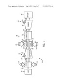
[0008] FIG. 1 is a block diagram of an embodiment of a turbine system having a service assembly with a removable access cover disposed over an access port;
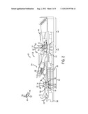
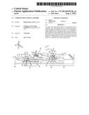
[0009] FIG. 2 is a cross-sectional side view of an embodiment of the turbine system of FIG. 1, illustrating a service assembly disposed between compressor stages and between turbine stages;
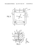
[0010] FIG. 3 is a partial top view of the turbine system of FIG. 2, as indicated by line 3-3 of FIG. 2, illustrating an embodiment of the service assembly with a removable access cover disposed over an access port along a casing of the turbine system;
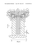
[0011] FIG. 4 is a partial cross-sectional side view of the turbine system of FIG. 2, taken within line 4-4 of FIG. 2, illustrating an embodiment of the service assembly with a removable access cover disposed over an access port, a vane, and a connection system between the removable access cover and the vane;
[0012] FIG. 5 is a partial cross-sectional side view of the service assembly of FIG. 4, taken within line 5-5 of FIG. 4, illustrating an embodiment of the connection system between the removable access cover and the vane;
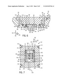
[0013] FIG. 6 is a partial cross-sectional side view of the turbine system of FIG. 2, taken within line 4-4 of FIG. 2, illustrating an embodiment of the service assembly with a removable access cover disposed over an access port, a vane, and a connection system between the removable access cover and the vane;
[0014] FIG. 7 is a cross-sectional end view of the service assembly taken along line 7-7 of FIG. 4, illustrating an embodiment of the connection system and a seal system of the removable access cover;
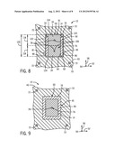
[0015] FIG. 8 is a cross-sectional end view of the service assembly taken along line 7-7 of FIG. 4, illustrating an embodiment of the connection system and a seal system of the removable access cover;
[0016] FIG. 9 is a cross-sectional end view of the service assembly taken along line 9-9 of FIG. 4, illustrating an embodiment of the connection system and a seal system of the removable access cover;
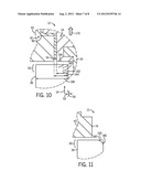
[0017] FIG. 10 is a partial cross-sectional side view of the service assembly taken within line 10-10 of FIG. 4, illustrating a rotary blade with damage (e.g., stress cracks) adjacent an access port covered by the removable access cover;
[0018] FIG. 11 is a partial cross-sectional side view of the service assembly taken within line 10-10 of FIG. 4, illustrating a rotary blade with repair (e.g., removal) of the damage after removal of the removable access cover from the access port;
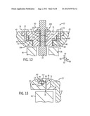
[0019] FIG. 12 is a partial cross-sectional side view of the turbine system of FIG. 2, taken within line 4-4 of FIG. 2, illustrating an embodiment of the service assembly with a removable access cover disposed over an access port, a vane, and a connection system enabling rotation of the vane relative to the removable access cover; and
[0020] FIG. 13 is a partial cross-sectional side view of the service assembly taken within line 10-10 of FIG. 4, illustrating an embodiment of a seal system between a removable access cover and an access port.
DETAILED DESCRIPTION OF THE INVENTION
[0021] One or more specific embodiments of the present invention will be described below. In an effort to provide a concise description of these embodiments, all features of an actual implementation may not be described in the specification. It should be appreciated that in the development of any such actual implementation, as in any engineering or design project, numerous implementation-specific decisions must be made to achieve the developers' specific goals, such as compliance with system-related and business-related constraints, which may vary from one implementation to another. Moreover, it should be appreciated that such a development effort might be complex and time consuming, but would nevertheless be a routine undertaking of design, fabrication, and manufacture for those of ordinary skill having the benefit of this disclosure.
[0022] When introducing elements of various embodiments of the present invention, the articles "a," "an," "the," and "said" are intended to mean that there are one or more of the elements. The terms "comprising," "including," and "having" are intended to be inclusive and mean that there may be additional elements other than the listed elements.
[0023] As discussed further below, the disclosed embodiments include a turbomachine service assembly with a removable access cover disposed over an access port of a turbomachine, such as a compressor or a turbine. For example, the access port may provide access to one or more rotary blades, thereby allowing inspection and servicing of the rotary blades without opening the entire casing of the turbomachine. In particular, the access port may overlap a blade tip of one or more rotary blades. If the blade tip has stress cracks or other damage, then the access port enables a tool to remove the damaged portion and blend or contour the rotary blade. In certain embodiment, the removable access cover may support a vane between adjacent rotary blades. The vane may be coupled to the removable access cover with a connection system, which blocks axial, radial, and circumferential movement of the vane relative to a rotational axis of the turbomachine. However, in some embodiments, the connection system may enable rotational motion of the vane relative to the removable access cover. Thus, the angle of the vane may be adjusted to control fluid flow through the turbomachine. Although the turbomachine service assembly may be employed in any type of turbomachine, the disclosed embodiments present the turbomachine service assembly in context of a turbine system.
[0024] Turning now to the drawings, FIG. 1 is a block diagram of an embodiment of a turbine system 10 having a plurality of service assemblies 12 configured to enable inspection and servicing of turbine components. In the illustrated embodiment, each service assembly 12 includes a removable access cover 14 disposed over an access port 16. As discussed below, each cover 14 and port 16 may overlap an internal turbine component, such as a rotary blade, to enable inspection and servicing of the component. The turbine system 10 includes a gas turbine engine 18 coupled to a load 20, such as an electrical generator. The gas turbine engine 18 includes a compressor 22 (e.g., one or more compressor stages), one or more combustors 24, and a turbine 26 (e.g., one or more turbine stages). In operation, the compressor 22 receives air 19 from an air intake 21, compresses the air in one or more compressor stages, and supplies compressed air 23 to each combustor 24 and associated fuel nozzles 28. The fuel nozzles 28 mix the compressed air 23 with fuel 25 to generate a fuel/air mixture 27, which is directed into the combustor 24. The fuel/air mixture 27 combusts in the combustor 24 to generate hot combustion gases 29, which are directed into the turbine 26. The hot combustion gases 29 drive the turbine 26 to rotate a shaft 30, which in turn drives rotation of the compressor 22 and the load 20. Eventually, the gases 29 exit the turbine 26 through an exhaust section 32.
[0025] FIG. 2 is a partial cross-sectional side view of an embodiment of the turbine system 10 of FIG. 1, illustrating an embodiment of the service assembly 12 disposed between adjacent rotary blades in both the compressor 22 and the turbine 26. In the illustrated embodiment, each service assembly 12 includes the cover 14, the port 16, and a vane 34 coupled to the cover 14. However, embodiments of the service assembly 12 may exclude the vane 34 depending on the particular location or configuration of the turbine system 10. The illustrated turbine system 10 includes the gas turbine engine 18 having a multi-stage compressor 22, a plurality of combustors 24, and a multi-stage turbine 26. For example, the multi-stage compressor 22 may include 1 to 20 compressor stages, wherein each compressor stage has a plurality of rotary blades 36 coupled to a compressor rotor 38 in an annular arrangement. The multi-stage compressor 22 also includes a plurality of stationary vanes 34 coupled to a compressor casing 40 (except for the vane 34 coupled to the cover 14) between compressor stages. Similarly, the multi-stage turbine 26 may include 1 to 20 turbine stages, wherein each turbine stage has a plurality of rotary blades 42 coupled to a turbine rotor 44 in an annular arrangement. The multi-stage turbine 26 also includes a plurality of stationary vanes or nozzles 46 coupled to a turbine casing 48 (except for the vane 46 coupled to the cover 14) between turbine stages. In both the multi-stage compressor 22 and the multi-stage turbine 26, a service assembly 12 may be disposed between any number of sequential stages of rotary blades 36 or 42.
[0026] As illustrated, each service assembly 12 enables access for inspection and servicing of internal components, such as rotary blades 36 within the compressor 22 and rotary blades 42 within the turbine 26. For example, the cover 14 and port 16 may at least partially overlap the adjacent rotary blades, such that the blade tips may be inspected and repaired through the port 16. The service assembly 12 also supports a vane (e.g., 34 or 46) between adjacent rotary blades (e.g., 36 or 42). In the illustrated embodiment, the vanes 34 and 46 are coupled to the respective covers 14 with a connection system 50. As discussed below, the connection system 50 is configured to block movement of the vanes 34 and 46 relative to the respective covers 14 in an axial direction 52, a radial direction 54, and a circumferential direction 56 with respect to a rotational axis 58. However, certain embodiments of the connection system 50 enable rotation movement 60 of the vanes 34 and 46 relative to the respective covers 14 to adjust the flow control provided by the vanes 34 and 46. Although the service assembly 12 may be coupled to the compressor 22, the turbine 26, or any other turbomachine, the following discussion presents embodiments of the service assembly 12 in context of the compressor 22.
[0027] FIG. 3 is a partial top view of the turbine system 10 of FIG. 2, as indicated by line 3-3 of FIG. 2, illustrating an embodiment of the service assembly 12 with the removable access cover 14 disposed over the access port 16 along the casing 40 of the compressor 22. The cover 14 is coupled to the casing 40 over the port 16 with a mounting system 70, which enables removal of the cover 14 for inspection and servicing through the port 16. As illustrated, the mounting system 70 includes fasteners 72 (e.g., threaded bolts) extending through the cover 14 into the casing 40 adjacent the port 16. For example, each fastener 72 may include a tool-engageable head 71 (e.g., a hex head) coupled to a threaded shaft 73, which threads through the cover 14 into the casing 40 until the head 71 biases an exterior surface 74 of the cover 14 inwardly toward the casing 40. As a result, the cover 14 is readily removable by unthreading the fasteners 72, and extracting the cover 14 from the port 16. The connection system 50 between the cover 14 and the vane 34 also includes a locking system 76 configured to lock the vane 34 in place, thereby blocking axial, radial, and circumferential movement of the vane 34 relative to the cover 14. For example, the illustrated locking system 76 includes a fastener 78 (e.g., a threaded bolt) that extends through the cover 14 into a portion of the vane 34. As discussed below, the fastener 78 may extend into a receptacle in the vane 34 to lock the position of the vane 34 relative to the cover 14. Again, the fastener 78 may include a tool-engageable head 77 (e.g., a hex head) coupled to a threaded shaft 79, which threads through the cover 14 into the vane 34.
[0028] FIG. 4 is a partial cross-sectional side view of the turbine system 10 of FIG. 2, taken within line 4-4 of FIG. 2, illustrating an embodiment of the service assembly 12 with the removable access cover 14 disposed over the access port 16, the vane 34, and the connection system 50 between the removable access cover 14 and the vane 34. In the illustrated embodiment, the cover 14 is coupled to the casing 40 over the port 16 via the mounting system 70, which includes the fasteners 72, a stepped mounting interface 80, and a seal system 81. The stepped mounting interface 80 includes a multi-step structure 82 of the cover 14 and a multi-step opening 83 of the port 16. As illustrated, the multi-step structure 82 of the cover 14 includes a radially outer portion (e.g., an upper flange portion 84) and a radially inner portion (e.g., an intermediate lip portion 85 and a plug portion 86). For example, the upper flange portion 84 is wider than the intermediate lip portion 85, while the intermediate lip portion 85 is wider than the plug portion 86. Similarly, the multi-step opening 83 of the port 16 includes an upper recess portion 87, an intermediate recess portion 88, and a through hole portion 89. For example, the upper recess portion 87 is wider than the intermediate recess portion 88, while the intermediate recess portion 88 is wider than the through hole portion 89. Accordingly, the service assembly 12 enables a stepped mounting of the cover 14 in the port 16. For example, the upper flange portion 84 rests in the upper recess portion 87, the intermediate lip portion 85 rests in the intermediate recess portion 88, and the plug portion 86 extends into the through hole portion 89.
[0029] In the illustrated embodiment, the mounting system 70 includes the fasteners 72 to secure the cover 14 to the casing 40 along the stepped mounting interface 80, while the seal system 81 includes a seal 90 (e.g., a step-shaped seal) configured to seal the cover 14 to the casing 40 along the stepped mounting interface 80. For example, the threaded shaft 73 of each fastener 72 threads through the upper flange portion 81 of the cover 14 into the casing 40 in the upper recess portion 85. As the fasteners 72 thread into the casing 40, the fasteners 72 drive the cover 14 against the casing 40 to compress the seal 90 along the stepped mounting interface 80. For example, the seal 90 may be compressed between the intermediate lip portion 85 and the intermediate recess portion 88, and between the plug portion 86 and the hole portion 89. In certain embodiments, the seal 90 may be made of metal, fabric, plastic, or any combination thereof.
[0030] As illustrated, the cover 14 (e.g., a fluid flow surface) and the hole portion 89 of the port 16 substantially overlap adjacent rotary blades 36 (e.g., different compressor stages), thereby enabling inspection and servicing of blade tips 37 of the rotary blades 36. For example, the hole portion 89 may overlap approximately 10 to 100 percent of the blade tips 37 of the adjacent rotary blades 36. In certain embodiments, the hole portion 89 may overlap at least approximately 10, 20, 30, 40, 50, 60, 70, 80, or 90 percent of one or both blade tips 37. As discussed in further detail below, this overlap of the hole portion 89 with the blade tips 37 enables in-situ service operations to repair blade tip damage (e.g., stress cracks) without disassembling the turbine system 10, e.g., the compressor 22. For example, the in-situ service operations may include removal of damaged material along the blade tips 37, and blending or contouring of the blade tips 37 after removal of the damaged material. In this manner, the performance of the rotary blades 36 may be improved without disassembling the turbine system 10, thereby improving fluid flow 62 along a fluid flow path 64 through stages of the rotary blades 36.
[0031] The vane 34 also improves the fluid flow 62 between stages of the rotary blades 36. In the illustrated embodiment, the connection system 50 couples the vane 34 to the cover 14 to fix the position of the vane 34. For example, the vane 34 may have a fixed angle relative to the fluid flow 62, and the connection system 50 may block movement of the vane 34 in the axial direction 52, the radial direction 54, and the circumferential direction 56 relative to the rotation axis 58 of the turbine system 10. In certain embodiments, the connection system 50 may enable rotation of the vane 34 relative to the cover 14 to enable adjustable flow control between the rotary blades 36. The illustrated connection system 50 includes the locking system 76 and a rail system 91, which includes a rail track 92 that mates with a rail groove 94. In the illustrated embodiment, the rail track 92 is disposed on the vane 34, while the rail groove 94 is disposed on the cover 14. In another embodiment, the rail track 92 may be disposed on the cover 14, while the rail groove 94 may be disposed on the vane 34. The illustrated rail system 91 provides a hook-type interface 96, e.g., a T-shaped interface, between the cover 14 and the vane 34. For example, the hook-type interface 96 includes a T-shaped cross-section 98 of the rail track 92 and a T-shaped cross-section 100 of the rail groove 94. In the illustrated configuration, the rail system 91 extends in the circumferential direction 56, such that the hook-type interface 96 blocks motion of the vane 34 relative to the cover 14 in the axial direction 52 and the radial direction 54. In another configuration, the rail system 91 may extend in the axial direction 52, such that the hook-type interface 96 blocks motion of the vane 34 relative to the cover 14 in the radial direction 54 and the circumferential direction 56.
[0032] In either configuration, the locking system 76 is configured to block movement of the vane 34 in the axial direction 52, the radial direction 54, the circumferential direction 56, or a combination thereof. As discussed above, the locking system 76 includes the fastener 78 to lock the position of the vane 34 relative to the cover 14. For example, the threaded shaft 79 of the fastener 78 may thread through the cover 14, penetrate the rail system 91, and contact the vane 34. As illustrated, the fastener 78 includes the tool-engageable head 77 coupled to the threaded shaft 79, which threads in the radial direction 54 through the cover 14 from the exterior surface 74 to an interior surface 102 of the rail groove 94, and into the rail track 92 from a surface 104 into a locking receptacle 106. For example, the locking receptacle 106 may be a cylindrical receptacle (e.g., a threaded receptacle), which receives a tip portion of the threaded shaft 79 to block movement of the vane 34 in the axial direction 52, the radial direction 54, and the circumferential direction 56.
[0033] FIG. 5 is a partial cross-sectional side view of the service assembly 12 of FIG. 4, taken within line 5-5 of FIG. 4, illustrating an embodiment of the connection system 50 between the removable access cover 14 and the vane 34. As illustrated, the locking system 50 includes the fastener 78 extending in the radial direction 54 through the cover 14 and partially into the rail track 92 within the rail groove 94. The threaded shaft 79 of the fastener 78 mates with a threaded hole 108 through the cover 14. Upon entering the rail system 91, the threaded shaft 79 extends in the radial direction 54 across a gap 110 between the interior surface 102 of the rail groove 94 (e.g., the cover 14) and the surface 104 of the rail track 92 (e.g., the vane 34). In one embodiment, the locking receptacle 106 in the rail track 92 may be a non-threaded cylindrical recess, such that the tip portion of the threaded shaft 79 biases the rail track 92 in the radial direction 54 toward the rotational axis 58 (e.g., biases the surfaces 102 and 104 away from one another to maintain or increase the gap 110). In another embodiment, the locking receptacle 106 in the rail track 92 may be a threaded cylindrical recess, such that the tip of the threaded shaft 79 pulls the rail track 92 in the radial direction 54 away from the rotational axis 58 (e.g., biases the surfaces 102 and 104 toward one another to decrease the gap 110). In either case, the engagement between the threaded shaft 79 and the locking receptacle 106 blocks movement of the vane 34 in the axial direction 52, the radial direction 54, and the circumferential direction 56.
[0034] FIG. 6 is a partial cross-sectional side view of the turbine system 10 of FIG. 2, taken within line 4-4 of FIG. 2, illustrating an embodiment of the service assembly 12 with the removable access cover 14 disposed over the access port 16, the vane 34, and the connection system 50 between the removable access cover 14 and the vane 34. In the illustrated embodiment, the locking system 76 and the seal system 81 have a different configuration than the embodiment of FIGS. 4 and 5. For example, the locking system 76 of FIG. 6 has the fastener 78 oriented in the axial direction 52, rather than the radial direction 54. In particular, the fastener 78 threads through a sidewall 111 of the rail groove 94 in the axial direction 52 into the locking receptacle 106 in a side surface 112 of the rail track 92. Thus, the fastener 78 biases the rail track 92 in the axial direction 52 within the rail groove 94. Similar to the embodiment of FIGS. 4 and 5, the engagement between the fastener 78 and the locking receptacle 106 blocks movement of the vane 34 in the axial direction 52, the radial direction 54, and the circumferential direction 56.
[0035] The seal system 81 of FIG. 6 has the seal 90 oriented along an interface 114 between the cover 14 and the casing 40. For example, the seal 90 may be a curved or a rectangular seal without any steps, rather than the stair-step configuration 109 of the seal 90 in FIGS. 4 and 5. In particular, the seal 90 extends into a recess 113 in the cover 14 and a recess 115 in the casing 40. As illustrated, the recess 113 is disposed along the intermediate lip portion 85 of the cover 14, while the recess 115 is disposed along the intermediate recess portion 88 of the port 16. However, one or more of the seals 90 may be disposed in various locations along the stepped mounting interface 80 between the cover 14 and the casing 40.
[0036] FIG. 7 is a cross-sectional end view of the service assembly 12 taken along line 7-7 of FIG. 4, illustrating an embodiment of the connection system 50 and the seal system 81 of the removable access cover 14. As discussed above, the connection system 50 may include the rail system 91 and the locking system 76. In the illustrated embodiment, the connection system 50 is configured to connect the vane 34 with the cover 14 along an axis 116 of the rail system 91. For example, the rail track 92 of the vane 34 may slide into the rail groove 94 of the cover 14 in the circumferential direction 56 along the axis 116, while the rail system 91 generally blocks movement of the vane 34 relative to the cover 14 in the axial direction 52 and the radial direction 54. As illustrated, the rail track 92 has a length 118 shorter than a length 120 of the rail groove 94. In other embodiments, the lengths 118 and 120 of the rail track 92 and the rail groove 94 may be substantially equal. However, as illustrated, the different lengths 118 and 120 may enable adjustability in the position of the rail track 92 in the rail groove 94, which in turn enables adjustability in the position of the vane 34 relative to the cover 14. For example, the rail track 92 may include a plurality of locking receptacles 106 at different positions along the axis 116, thereby enabling the fastener 78 to secure the rail track 92 at a plurality of different positions. As illustrated, the rail track 92 includes three locking receptacles 106 at different positions along the axis 116, although any number (e.g., 1 to 10 or more) of locking receptacles 106 may be disposed along the rail track 92. In this manner, the fastener 78 may lock the rail track 92 in the rail groove 94 at multiple positions to change the location of the vane 34 relative to the cover 14.
[0037] As illustrated in FIG. 7, the seal system 81 extends the seal 90 in the circumferential direction 56 along opposite sides 122 of the cover 14 between the cover 14 and the port 16, i.e., parallel to the axis 116 of the rail system 91. In addition, the seal system 81 may extend the seal 90 in the axial direction 52 along opposite sides 124 of the cover 14 between the cover 14 and the port 16, i.e., perpendicular to the axis 116 of the rail system 91. However, the seal 90 extending along the opposite sides 124 may be positioned above the rail system 91 (i.e., along a portion of the cover 14 away from the rail groove 94). For example, the seal 90 may extend along the opposite sides 124 between the intermediate lip portion 85 and the intermediate recess portion 88 and/or between the upper flange portion 84 and the upper recess portion 87.
[0038] FIG. 8 is a cross-sectional end view of the service assembly 12 taken along line 7-7 of FIG. 4, illustrating an embodiment of the connection system 50 and the seal system 81 of the removable access cover 14. In the illustrated embodiment, the connection system 50 mounts a plurality of vanes 34 to the cover 14 via the rail system 91. In particular, the rail system 91 supports a pair of vanes 34 along the cover 14. However, other embodiments of the connection system 50 may support any number of vanes 34 per cover 14 via the rail system 91 (e.g., 1 to 10 or more). Each vane 34 includes a rail track 92 disposed along the rail groove 94 in the cover 14. For example, the illustrated rail tracks 92 each have a length 118 approximately half the length 120 of the rail groove 94. Each rail track 92 is coupled to the rail groove 94 via the locking system 76. For example, the illustrated locking system 76 secures each rail track 92 within the rail groove 94 via a fastener 78 disposed in a locking receptacle 106 of the respective rail track 92. Similar to the embodiment of FIG. 7, the seal system 81 extends the seal 90 along the opposite sides 122 and the opposite sides 124 of the cover 14.
[0039] FIG. 9 is a cross-sectional end view of the service assembly 12 taken along line 9-9 of FIG. 4, illustrating an embodiment of the connection system 50 and the seal system 81 of the removable access cover 14. As shown, the seal system 81 includes the seal 90 extending completely around the cover 14 between the cover 14 and the port 16. For example, the illustrated seal 90 has a rectangular shape (with a stair-step configuration 109 as illustrated in FIG. 4) disposed between a rectangular portion of the cover 14 and a rectangular portion of the port 16. Accordingly, the seal 90 may completely seal the cover 14 to the port 16 to block any leakage from within the casing 40.
[0040] FIG. 10 is a partial cross-sectional side view of the service assembly 12 taken within line 10-10 of FIG. 4, illustrating a rotary blade 36 with damage 160 (e.g., stress cracks) along a blade tip portion 161 adjacent the access port 16 covered by the removable access cover 14. As illustrated, the cover 14 and the access port 16 substantially overlap the blade 36 (e.g., blade tip portion 161) in the axial direction 52, as indicated by overlap distances 162 and 164. The overlap distance 162 represents a portion of a fluid flow surface 166 of the cover 14 extending in the axial direction 52 along the blade tip portion 161, while the overlap distance 164 represents a portion of the port 16 extending in the axial direction 52 along the blade tip portion 161. In certain embodiments, the overlap distance 162 and/or 164 may be approximately 10 to 100 percent of a blade width 168. For example, the overlap distance 162 and/or 164 may be greater than approximately 10, 20, 30, 40, 50, 60, 70, 80, or 90 percent of the blade width 168. Furthermore, as discussed above, the service assembly 12 (e.g., cover 14 and port 16) may provide access to multiple stages of rotary blades 36, such as two stages of rotary blades 36. As a result, the rotary blade 36, and particularly the damage 160 along the blade tip portion 161, is viewable and accessible upon removal of the cover 14 and vane 34. For example, as discussed above, the cover 14 and vane 34 may be extracted from the port 16 in the radial direction 54, as indicated by arrow 170, after releasing the mounting system 70 (e.g., fasteners 72).
[0041] FIG. 11 is a partial cross-sectional side view of the service assembly 12 taken within line 10-10 of FIG. 4, illustrating the rotary blade 36 with repair 180 (e.g., removal) of the damage 160 after removal of the removable access cover 14 and vane 34 from the access port 16. As illustrated, the removal of the cover 14 and vane 34 provides a substantially unobstructed view of the rotary blade 36, and particularly the blade tip portion 161, through the port 16. Using the port 16, a service technician may view the rotary blade 36, identify any damage such as the damage 160 along the blade tip portion 161 as illustrated in FIG. 10, and then repair the damage as illustrated in FIG. 11. As illustrated, the original damage 160 is represented with a dashed line, whereas the repair 180 is represented with a solid line. In certain embodiments, the service technician may perform a blending or contouring procedure, such that the illustrated repair 180 has a blended or contoured surface 182, which is configured to reduce stress and improve performance of the rotary blade 36. After inspection and repair of the rotary blade 36, the service technician may rotate the rotor in the circumferential direction 56 to step to a subsequent rotary blade 36, inspect and repair (if needed) the rotary blade 36, and then continuing stepping through rotary blades 36 until all rotary blades have been inspected and repaired (if needed) in the particular stage. In this manner, the rotary blades 36 may be inspected and repaired to improve performance without substantially disassembling the turbine system 10, e.g., without removing the casing of the compressor 22 or the turbine 24.
[0042] FIG. 12 is a partial cross-sectional side view of the turbine system 10 of FIG. 2, taken within line 4-4 of FIG. 2, illustrating an embodiment of the service assembly 12 with the removable access cover 14 disposed over the access port 16, the vane 34 disposed between stages of rotary blades 36, and the connection system 50 enabling rotation of the vane 34 relative to the removable access cover 14. In the illustrated embodiment, the connection system 50 includes a rotational connection system 200 between the vane 34 and the cover 14. For example, the rotational connection system 200 includes a rotational shaft 202 disposed in a rotational support receptacle or bore 204, such that the rotational shaft 202 is able to rotate within the bore 204. The connection system 200 also may include an annular bushing, seal, and/or bearing 206 between the rotational shaft 202 and the bore 204. For example, the bushing 206 may be configured to reduce friction during rotation, while also maintaining a seal between the shaft 202 and the bore 204. As illustrated, the rotational shaft 202 supports the vane 34, thereby allowing rotational adjustment of the vane 34 in the rotational direction 60, as indicated by opposite rotational arrows 208 and 210. In this manner, the service assembly 12 enables removal of the cover 14 and vane 34 from the port 16 for servicing, while also enabling rotational adjustment of the vane 34 to improve performance of the turbine system 10.
[0043] FIG. 13 is a partial cross-sectional side view of the service assembly 12 taken within line 10-10 of FIG. 4, illustrating an embodiment of the seal system 81 between the removable access cover 14 and the access port 16. The illustrated seal system 81 is similar to the embodiment of FIG. 6, and may be used in any of the embodiments discussed above, including the embodiments of FIGS. 4 and 12. As illustrated, the seal system 81 includes the seal 90 oriented along the interface 114 between the cover 14 and the casing 40. For example, the illustrated seal 80 extends into the recess 113 in the cover 14 and the recess 115 in the casing 40. As illustrated, the recess 113 is disposed along the intermediate lip portion 85 of the cover 14, while the recess 115 is disposed along the intermediate recess portion 88 of the port 16. However, one or more of the seals 90 may be disposed in various locations along the stepped mounting interface 80 between the cover 14 and the casing 40. In this manner, the seal system 81 is configured to block any leakage through the access port 16 from within the casing 40.
[0044] Technical effects of the invention include a turbomachine service assembly to enable inspection and repair of rotary blades without substantially disassembling a turbomachine, e.g., without removing a casing. For example, the service assembly may include a cover disposed in an access port, which at least substantially overlaps blade tips of one or more stages of rotary blades. Upon removal of the cover, the access port provides an unobstructed view of a substantial portion of the rotary blades, e.g., greater than 50 percent of each blade tip. The unobstructed view of the blade tips simplifies inspection of the blade tips, and enables repair operations to remove damaged areas of the blade tips. As a result, a service technician is able to more quickly inspect and repair rotary blades, thereby improving operational performance and reducing the possibility of greater damage of the turbomachine.
[0045] This written description uses examples to disclose the invention, including the best mode, and also to enable any person skilled in the art to practice the invention, including making and using any devices or systems and performing any incorporated methods. The patentable scope of the invention is defined by the claims, and may include other examples that occur to those skilled in the art. Such other examples are intended to be within the scope of the claims if they have structural elements that do not differ from the literal language of the claims, or if they include equivalent structural elements with insubstantial differences from the literal language of the claims.
User Contributions:
Comment about this patent or add new information about this topic:
Images included with this patent application:
 |  |
 |  |
 |  |
 |  |
 |
| Similar patent applications: | |
| Date | Title |
|---|---|
| 2012-04-19 | Turbomachine seal assembly |
| 2013-02-21 | Turbomachine seal assembly |
| 2013-05-30 | Turbomachine casing assembly |
| 2013-06-13 | Turbomachine casing assembly |
| 2013-07-25 | Turbomachine casing assembly |
| New patent applications in this class: | |
| Date | Title |
|---|---|
| 2019-05-16 | Water pump |
| 2015-12-10 | Ventilation system and ventilation fan housing thereof |
| 2015-05-14 | Method and means for establishing access to the main parts in the nacelle on a wind turbine |
| 2015-05-07 | Atr axial v-groove |
| 2015-05-07 | Integrated nozzle and plug |
| New patent applications from these inventors: | |
| Date | Title |
|---|---|
| 2015-11-12 | System and method for evaluating opportunities to extend operating durations |
| Top Inventors for class "Rotary kinetic fluid motors or pumps" | |
| Rank | Inventor's name |
|---|---|
| 1 | Gabriel L. Suciu |
| 2 | Frederick M. Schwarz |
| 3 | United Technologies Corporation |
| 4 | Brian D. Merry |
| 5 | Craig M. Beers |