Patent application title: ELECTRONIC DEVICE AND PORT CONNECTOR THEREOF
Inventors:
Yung-Hung Chu (Tu-Cheng, TW)
Fu-Fa Le (Shenzhen City, CN)
Song-Ling Yang (Shenzhen City, CN)
Assignees:
HON HAI PRECISION INDUSTRY CO., LTD.
HONG FU JIN PRECISION INDUSTRY (ShenZhen) CO., LTD.
IPC8 Class:
USPC Class:
361748
Class name: Housing or mounting assemblies with diverse electrical components for electronic systems and devices printed circuit board
Publication date: 2012-06-14
Patent application number: 20120147569
Abstract:
An electronic device includes a main body and a port connector. The main
body includes a printed circuit board, a bottom plate and a side plate
cooperatively defining a opening. The printed circuit board is fixed
parallelly to the bottom plate. The port connector includes an outer
angled plate having a first wall, a second wall, and first pins and
second pins. The first wall is attached to the bottom plate and defines
first ports. The second wall is attached to the side plate and defines
second ports. Each of the first pins is retained within one of the first
ports and contacting the printed circuit board. Each of the second pins
is retained within one of the second ports and contacting the printed
circuit board.Claims:
1. An electronic device comprising: a main body comprising a bottom
plate, a side plate, and a printed circuit board, wherein the bottom
plate and the side plate cooperatively defines an opening, and the
printed circuit board is fixed parallelly to the bottom plate; and a port
connector comprising: an outer angled plate comprising a first wall
attached to the bottom plate and a second wall attached to the side
plate, wherein the first wall defines a plurality of first ports, the
second wall defines a plurality of second ports; a plurality of first
pins, wherein each of the first pins is retained within one of the first
ports and contacting the printed circuit board; and a plurality of second
pins, wherein each of the second pins is retained within one of the
second ports and contacting the printed circuit board.
2. The electronic device as described in claim 1, wherein the electronic device is a watch phone.
3. The electronic device as described in claim 1, wherein the bottom plate comprises a first support edge, the side plate comprises a second support edge adjacent to the first edge, the first support and the second support edge cooperatively define the opening therethrough, and the port connector is attached to the first support edge and the second support edge.
4. The electronic device as described in claim 1, wherein the port connector further comprises an inner angled plate comprising a third wall attached to the first wall and a fourth wall attached to the second wall, wherein the third wall defines a plurality of third ports and fourth ports, each of the third ports is correspondingly aligned with one of the first ports, and each of the fourth ports is correspondingly aligned to one of the second ports.
5. The electronic device as described in claim 4, wherein each of the first pins includes a first tab and a second tab extending perpendicular to each other, the first tab is retained within the first port, and the second tab is retained within the third port for contacting the printed circuit board.
6. The electronic device as described in claim 4, wherein each of the second pins includes a third tab and a fourth tab extending parallel to each other, the third tab is retained within the second port, and the fourth tab is retained with the in fourth port for contacting the printed circuit board.
7. A port connector comprising: an outer angled plate comprising a first wall and a second wall connected to each other, wherein the first wall defines a plurality of first ports, the second wall defines a plurality of second ports; a plurality of first pins, wherein each of the first pins is retained within one of the first ports and contacting the printed circuit board; and a plurality of second pins, wherein each of the second pins is retained within one of the second ports and contacting the printed circuit board.
8. The port connector as described in claim 7, wherein the port connector further comprises an inner angled plate comprising a third wall attached to the first wall and a fourth wall attached to the second wall, wherein the third wall defines a plurality of third ports and fourth ports, each of the third ports is correspondingly aligned with one of the first ports, and each of the fourth ports is corresponding aligned to one of the second ports.
9. The port connector as described in claim 8, wherein each of the first pins includes a first tab and a second tab extending perpendicular to each other, the first tab is retained within the first port, and the second tab is retained within the third port for contacting the printed circuit board.
10. The port connector as described in claim 8, wherein each of the second pins includes a third tab and a fourth tab extending parallel to each other, the third tab is retained within the second port, and the fourth tab is retained with the in fourth port for contacting the printed circuit board.
Description:
BACKGROUND
[0001] 1. Technical Field
[0002] The present disclosure relates to an electronic device and a port connector thereof.
[0003] 2. Description of Related Art
[0004] Electronic devices such as digital cameras and others often have a port connector for exchange of data with other devices. Although conventional port connectors satisfy basic requirements, there is still a need for an improved port connector for electronic devices.
BRIEF DESCRIPTION OF THE DRAWINGS
[0005] Many aspects of the embodiments can be better understood with reference to the following drawings. The components in the drawings are not necessarily drawn to scale, the emphasis instead being placed upon clearly illustrating the principles of the present disclosure. Moreover, in the drawings, like reference numerals designate corresponding parts throughout the several views.
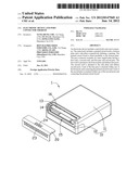
[0006] FIG. 1 is an isometric of view of an electronic device according to an exemplary embodiment.
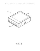
[0007] FIG. 2 is an isometric view of the electronic device of FIG. 1, viewed from a reverse perspective.
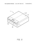
[0008] FIG. 3 is an exploded view of the electronic device of FIG. 1.
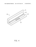
[0009] FIG. 4 is an enlarged, isometric view of a port connector of the electronic device of FIG. 1.
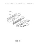
[0010] FIG. 5 is an exploded view of the port connector of FIG. 4.
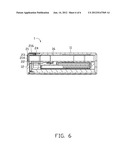
[0011] FIG. 6 is a cross-section view of the electronic device taken along the line VI-VI of FIG. 1.
DETAILED DESCRIPTION
[0012] Embodiments of the present disclosure are now described in detail, with reference to the accompanying drawings.
[0013] Referring to FIGS. 1 and 2, an electronic device 1 according to an exemplary embodiment is illustrated. The electronic device 1 includes a main body 10 and a port connector 20 connected to the main body 10. In the embodiment, the electronic device 1 is a watch phone.
[0014] Referring to FIG. 3, the main body 10 includes a bottom plate 11 and a side plate 12 connected to the bottom plate 11. The bottom plate 11 includes a first support edge 13, and the side plate 12 includes a second support edge 14 adjacent to the first support edge 13. The main body 10 defines an opening 15 extending through both the first support edge 13 and the second support edge 14. The main body 10 further includes a printed circuit board 16 extending parallel to the bottom plate 11.
[0015] Referring to FIGS. 4 and 5, the port connector 20 includes an outer angled plate 21, an inner angled plate 22, and a number of first pins 23 and second pins 24. The outer angled plate 21 includes a first wall 210 and a second wall 212 connected to each other, forming an angle. The first wall 210 defines a number of first ports 214 extending therethrough. The second wall 212 defines a number of second ports 216 extending therethrough. The inner angled plate 22 includes a third wall 220 attached to the first wall 210 and a fourth wall 222 attached to the second wall 212. The fourth wall 222 defines a number of third ports 224 and fourth ports 226. The third ports 224 are correspondingly aligned with the first ports 212, and the fourth ports 226 are correspondingly aligned with the second ports 216. The first pins 23 and the second pins 24 are made of electrically conductive material. The first pin 23 includes a first tab 230 and a second tab 232 extending perpendicular to each other. The first tab 230 is retained within the first port 214, and the second tab 232 is retained within the third port 224 for contacting the printed circuit board 16. The second pin 24 includes a third tab 240 and a fourth tab 242 extending parallel to each other. The third tab 240 is retained within the second port 216, and the fourth tab 242 is retained with the in fourth port 226 for contacting the printed circuit board 16.
[0016] Referring also to FIG. 6, after assembling the port connector 20 to the main body 10, the outer angled plate 21 is attached to the first support edge 13 and the second support edge 14, and the inner angled plate 22 is retained within the opening 15. The first pins 23 and the second pins 24 electrically contact the printed circuit board 16. Thus the electronic device 1 can exchange data with other devices through the port connector 20.
[0017] While various embodiments have been described and illustrated, the disclosure is not to be constructed as being limited thereto. Various modifications can be made to the embodiments by those skilled in the art without departing from the true spirit and scope of the disclosure as defined by the appended claims.
User Contributions:
Comment about this patent or add new information about this topic:
Images included with this patent application:
 |  |
 |  |
 |  |
 |
| Similar patent applications: | |
| Date | Title |
|---|---|
| 2011-08-18 | Electronic device and plug connector thereof |
| 2011-10-06 | Electronic device with rotatable keypad and method for controlling the electronic device |
| 2011-09-29 | Electronic device and method for producing electronic device |
| 2011-10-06 | Power source voltage protective device and power source voltage protection method |
| 2011-09-22 | Electronic device, and method of manufacturing electronic device |
| New patent applications in this class: | |
| Date | Title |
|---|---|
| 2022-05-05 | Force sensing dome switch |
| 2019-05-16 | Circuit board structure |
| 2019-05-16 | Devices comprising a capacitor and support material that laterally supports the capacitor |
| 2018-01-25 | Heat-insulation material and production method thereof |
| 2017-08-17 | Three-dimensional circuit substrate and sensor module using three-dimensional circuit substrate |
| New patent applications from these inventors: | |
| Date | Title |
|---|---|
| 2013-12-12 | Electronic device with camera module and remote signal receiver |
| 2013-01-03 | Heat dissipater and printed circuit board module |
| 2012-12-27 | Wireless keyboard and computer system using the same |
| 2012-12-06 | Projector holder and projector system having the same |
| 2012-11-29 | Projector and reflector thereof |
| Top Inventors for class "Electricity: electrical systems and devices" | |
| Rank | Inventor's name |
|---|---|
| 1 | Zheng-Heng Sun |
| 2 | Levi A. Campbell |
| 3 | Li-Ping Chen |
| 4 | Robert E. Simons |
| 5 | Richard C. Chu |