Patent application title: TOWER FOR A SOLAR CONCENTRATION PLANT WITH NATURAL DRAUGHT COOLING
Inventors:
Rafael Olavarria Rodríguez-Arango (Sevilla, ES)
Elena García Ramírez (Sevilla, ES)
Josê Barragán Jiménez (Sevilla, ES)
Assignees:
ABENGOA SOLAR NEW TECHNOLOGIES, S.A.
IPC8 Class: AF24J207FI
USPC Class:
126569
Class name: Stoves and furnaces solar heat collector
Publication date: 2012-05-31
Patent application number: 20120132193
Abstract:
Solar concentration plant placed on tower technology wherein the tower is
used not only to equate the receiver devices at great height but also as
a natural-draft cooling system. The tower is hollow and has a
hyperboloid. structure that may exceed 200 m in height, accommodating
devices for receiving saturated or superheated steam in cavities with
different orientations. There is a dynamic control for adapting the
heliostat field so that the heliostats can be focussed on different focal
points for producing electricity, producing process heat, producing solar
fuels or for application to thermochemical processes.Claims:
1. Tower for a solar concentration plant with natural-draught cooling
having a hollow circular base and hyperboloid structure, wherein it
comprises a tower with sufficient height to minimise the cosine effect
and having, on its highest part, several rectangular balconies or
overhangs with different orientations; each of said balconies or
overhangs contains a cavity with an outer opening accommodating one or
several solar receiver devices, the construction material of the tower
being concrete, metal or an equivalent material, except for the areas
adjacent to the outer openings of the cavities, which will be protected
by insulating plates, as in the case of the inner areas of the cavities
that are not occupied by the solar receiver device.
2. Tower for a solar concentration plant with natural-draught cooling, according to claim 1, wherein the receiver devices may be saturated or superheated steam receiver devices installed independently on the different balconies or overhangs, including a tank by way of connection therebetween.
3. Tower for a solar concentration plant with natural-draught cooling, according to claim 1, wherein the tower exceeds 100 m in height.
4. Tower for a solar concentration plant with natural-draught cooling, according to claim 1, wherein the hollow circular base has a diameter of approximately 50 m, the tower exceeds 200 m in height, the dimensions of the overhangs are approximately 24 m wide by 50 m high and the cavities have an outer opening approximately 20 m wide by 17 m high which accommodates a solar receiver device.
Description:
TECHNICAL FIELD OF THE INVENTION
[0001] The present invention relates to solar concentration plants placed on tower technology having a natural-draught system and physically separated from the evaporator and superheater, as well as dynamic control for adapting the heliostat field for producing electricity, producing process heat, producing solar fuels or for application to thermochemical processes.
BACKGROUND OF THE INVENTION
[0002] Within high solar concentration plants we can distinguish Stirling disks, parabolic trough collectors and the technology discussed herein, central receiver technology.
[0003] Central receiver systems consist of a heliostat field, made up of mirrors with a large surface area (40-125 m2 per unit) called sun-tracking heliostats, which reflect the direct solar radiation incident upon one or several central receiver devices located on the highest part of a very high tower. These receiver devices are usually found accommodated in cavities "excavated" in the tower itself.
[0004] Concentrated solar radiation heats a fluid inside the receiver, the thermal energy of which can subsequently be used to generate electricity.
[0005] At present, water/steam technology is that most frequently used in central receiver systems, using both saturated and superheated steam as a heat-transfer fluid.
[0006] In order to reduce electricity consumption in conventional thermal plants, so-called natural-draught cooling or hyperbolic cooling is used.
[0007] The air flow through the natural-draught tower is mainly due to the difference in density between the cold inflowing air and warm outflowing air, thereby eliminating the need for mechanical fans. These towers have low maintenance costs and are highly recommended for cooling large amounts of water.
[0008] Natural-draught towers must be high and must also have a large cross section in order to facilitate the flow of ascendant air.
DESCRIPTION OF THE INVENTION
[0009] The invention being discussed is that of a solar tower used as a natural-draught cooling tower in a high concentration thermoelectric solar plant, where the concentrator element is a field of heliostats that concentrate solar radiation on several receiver devices installed on the highest part of said tower.
[0010] The steam originating in said receiver devices is pumped towards a turbine for producing electricity.
[0011] In order to facilitate this natural-draught effect, the tower of the invention also has a hyperbolic and hollow structural design, in such a manner as to enable an ascendant air current for cooling the steam by natural convection to travel up therethrough.
[0012] Using the solar tower as a cooling tower, it has a dual function: that of accommodating the receiver devices at the necessary height for concentrating the radiation and use as a cooling tower.
[0013] The tower of our heliostat field has the necessary height to concentrate the solar energy reflected by the heliostat field onto a focus or focal point located on the highest part thereof, thereby minimising cosine effect losses (angle formed between the incident ray and the normal to the heliostat, completely shadowing the sun). We are referring to tower heights in excess of 100 m, said height being sufficient to facilitate use of the tower for this natural-draught cooling effect.
[0014] This natural circulation is also aided by the existence of a hot focal point such as the receiver devices on the highest part of the tower.
[0015] The hollow design of the tower for use as a natural-draught tower obliges us to devise another way of accommodating the receivers so that these do not interrupt the outward flow of air, as in the towers of the state of the art the receiver devices are disposed within inner cavities, which significantly hampers outflow of air.
[0016] To this end, the use of balconies or overhangs that include the different cavities or receiver devices has been devised in such a manner that the equipment does not interrupt the natural-draught effect achieved using a completely hollow tower.
[0017] These receiver devices can be saturated and superheated steam receiver devices or receiver devices of any other heat-transfer fluid, disposed independently on the different balconies or overhangs and including a tank by way of connection therebetween in the case of water/steam receiver devices. The tower could also be designed in such a manner as to accommodate several receiver devices in the same cavity.
[0018] In order for the plant to produce high outputs (approximately 50 MWe) of commercial interest, the heliostat field required for this type of high-output plant tends towards field configurations having a large number of heliostats.
[0019] Therefore, the tower proposed herein would have three or four focal points with different orientations, depending on the number of cavities chosen.
DESCRIPTION OF THE DRAWINGS
[0020] In order to complete the description being made and with the object of helping to better understand the invention, it is accompanied by a set of drawings wherein, in an illustrative and non-limiting manner, the following have been represented:
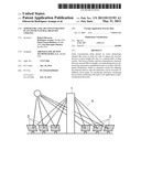
[0021] FIG. 1 shows a general schematic view of a solar concentration plant with a tower-type central receiver
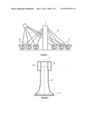
[0022] FIG. 2 shows an elevational view of the tower
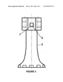
[0023] FIG. 3 shows a rear elevational view of the tower
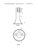
[0024] FIG. 4 shows a side elevational view of the tower
[0025] FIG. 5 shows a top plan view of the tower
[0026] The references used in the figures correspond to: [0027] (1) Tower [0028] (2) Heliostats [0029] (3) Solar radiation [0030] (4) Tower base [0031] (5) Tower hyperboloid structure [0032] (6) Overhangs or balconies [0033] (7) Receiver devices [0034] (8) Cavity [0035] (9) Cavity [0036] (10) Cavity
PREFERRED EMBODIMENT OF THE INVENTION
[0037] In order to better understand the invention, a description of the tower design and geometry is provided below.
[0038] FIG. 1 shows the usual configuration of a solar concentration plant having a central receiver in the form of a tower. It is composed of the tower (1) which accommodates, on the highest part thereof, the receiver devices (3) whereonto the solar radiation is reflected by the heliostats (2), which are subject to different focussing strategies in order to achieve the required thermal output and concentration in each receiver device.
[0039] FIG. 2 shows a detailed view of the tower (1) geometry. The tower (1) has a hollow circular base (4) with a diameter of approximately 50 m. The tower has a hyperboloid structural design (5) that may exceed 200 m in height, taking into account that these dimensions may vary according to the concentration plant's requirements.
[0040] Three or four rectangular overhangs (6) or balconies, depending on the distribution of the heliostats (2), are deployed on the highest part of the tower. The dimensions of said overhangs (6) are 24 m wide by 50 m high, although said dimensions may vary in accordance with design requirements.
[0041] Each of the overhangs (6) contains a cavity (8, 9, 10) with an outer opening approximately 20 m wide by 17 m high that accommodates a solar receiver device.
[0042] The receiver devices (7) can be saturated or superheated steam receivers and are installed independently on the different balconies or overhangs (6), including a tank by way of connection therebetween.
[0043] The construction material of the tower (1) can be concrete, metal or an equivalent material, except for the areas adjacent to the outer openings of the cavities (8, 9, 10), which will be protected by insulating plates in order to protect the concrete from the solar radiation.
[0044] The interior of the cavity that is not occupied by the solar receiver device (7) will also be protected by this insulating material.
[0045] In relation to the heliostat field (2), these types of high-output plants require field configurations with a large number of heliostats (2) and different orientations. Therefore, the tower (1) of the proposed thermoelectric solar plant would have three or four focal points with different orientations, depending on the chosen number of cavities.
[0046] Additionally, in order to manage the steam produced and ensure availability thereof in the absence of daylight hours, the plant includes a storage system based on either water/steam tanks or molten salts.
[0047] As explained earlier, the choice of this tower design is basically due to the possibility of reducing the internal electricity consumption and water consumption of a themiosolar power generation plant using one of the existing construction elements: the tower. The tower thus becomes a dual-function element: it raises the solar receiver devices and enables an air-based natural cooling system. This cooling system substitutes conventional water-based cooling towers, thus reducing in-plant electricity consumption and water consumption.
User Contributions:
Comment about this patent or add new information about this topic:
Images included with this patent application:
 |  |
 |  |
| Similar patent applications: | |
| Date | Title |
|---|---|
| 2013-05-23 | Modular solar receiver and solar power plant comprising at least one such receiver |
| 2013-02-07 | Oven appliance with dual opening doors |
| 2013-05-16 | Solar tube panel with dual-exposure heat absorption |
| 2008-12-25 | Condensate pan with condensate trap |
| 2011-05-05 | Low cost fixed focal point parabolic trough |
| New patent applications in this class: | |
| Date | Title |
|---|---|
| 2016-09-01 | Solar energy absorptive coating, arrangement of the coating on a substrate, method for manufacturing the arrangement and use of the arrangement |
| 2013-09-19 | Solar system cleaning apparatus |
| 2013-07-04 | Thermal insulator having infrared-reflective coating |
| 2013-04-25 | Solar water heating system with double-row vacuum tubes |
| 2013-01-24 | Solar energy collecting modules and method for assembling the same |
| New patent applications from these inventors: | |
| Date | Title |
|---|---|
| 2012-05-31 | Method for the natural-draught cooling of a solar concentration plant |
| 2012-05-31 | System and method for accumulating steam in tanks for solar use |
| Top Inventors for class "Stoves and furnaces" | |
| Rank | Inventor's name |
|---|---|
| 1 | Paul Bryan Cadima |
| 2 | David Deng |
| 3 | Andrew Plotkin |
| 4 | Peter Emery Von Behrens |
| 5 | Derek W. Schrock |