Patent application title: All-in-one hand held wrap material dispensing and storage apparatus
Inventors:
Henry Mathew Elash (Surrey, CA)
Sandra Corinne Elash (Surrey, CA)
IPC8 Class: AB65D8567FI
USPC Class:
206389
Class name: Special receptacle or package for roll or reel
Publication date: 2012-05-24
Patent application number: 20120125794
Abstract:
A cylindrical tube for dispensing wrap material, comprising an outer
surface having a flat portion, the flat portion for resting on a surface;
an inside diameter sized for receiving the wrap material; a cut-out in
the cylindrical tube for exposing an end of the wrap material; and a
groove formed in an outer surface of the cylindrical tube.Claims:
1. A cylindrical tube for dispensing wrap material, comprising: an outer
surface having a flat portion, the flat portion for resting on a surface;
an inside diameter sized for receiving the wrap material; a cut-out in
the cylindrical tube for exposing an end of the wrap material; and a
groove formed in an outer surface of the cylindrical tube.
2. A cylindrical tube as claimed in claim 1, comprising end caps received on ends of the cylindrical tube.
3. A cylindrical tube as claimed in claim 1, comprising a partition for defining a portion of the cylindrical tube for receiving accessories.
Description:
CROSS REFERENCE TO RELATED APPLICATIONS
[0001] The present application claims the benefit of priority of U.S. Provisional Patent Application No. 61/415,583, filed Nov. 21, 2010, which incorporated herein by reference in its entirety.
FIELD
[0002] The present disclosure relates to hand held material dispensing and storage apparatus.
SUMMARY
[0003] A new and useful hand-held apparatus for storing, dispensing and cutting wrap material in selected lengths that may be comprised of wrap such as gift wrap paper, foil, plastic, kraft paper, construction paper, packaging paper, but are not limited to and is not intended to limit the scope of the invention.
[0004] The distinguishable feature; a novel characteristic of the apparatus is that it could be used for storing wrap material and for storing wrapping accessories within the apparatus, such as a plastic cutting knife, tape, bows, ribbons, gift tags, writing device, but are not limited to and is not intended to limit the scope of the invention. Another distinguishable characteristic is that the apparatus is cylindrical tubing with a notched-out groove, a cut-out portion and a cut off portion removed.
[0005] The notched-out groove provides for a cutting edge to be used as a guide with the application of the cutting knife for cutting the wrap material straight. The cut-out portion allows for loading the wrap material into the centre of the apparatus and same cut-out portion allows for dispensing of the desired, selected length of wrap. A portion of the cylindrical tubing is cut off the entire length of the apparatus to make a flat bottom surface which provides stability while cutting the desired length of wrap material. No features protrude from the apparatus itself other than the wrap material when in use and the two end caps. The apparatus consists of a cylindrical tube with a partition separating the wrap material and the wrapping accessories. The apparatus also includes two removable end caps (one on each end of the tube) to hold in the wrap material during use and storage and also to secure the accessories when the apparatus is not in use. A spacer is provided which could be inserted into the end of the apparatus in which the roll of wrap is inserted to accommodate for shorter lengths of the wrap material, enabling the roll to remain in a proper position for dispensing the wrap material straight.
BRIEF DESCRIPTION OF THE DRAWINGS
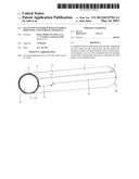
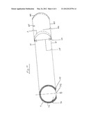
[0006] FIG. 1 is a front view of an apparatus for dispensing and storing wrap material;
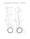
[0007] FIG. 2 is a back view of the apparatus of FIG. 1;
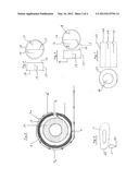
[0008] FIG. 3 is an end view of the apparatus of FIG. 1;
[0009] FIGS. 4 and 5 are views of end caps of the apparatus of FIG. 1;
[0010] FIG. 6 is a side view and end view of a cutting device;
[0011] FIG. 7 is a side view and an end view of a spacer material;
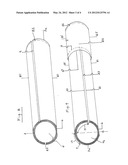
[0012] FIG. 8 is a front view of an apparatus for dispensing and storing wrap material according to another embodiment;
[0013] FIG. 9 is a front view of the apparatus for dispensing and storing wrap material of FIG. 8 including an end cap;
[0014] FIG. 10 is a front view of an apparatus for dispensing and storing wrap material yet another embodiment.
[0015] The drawings that are provided are for specific examples, but are not limited to and are not intended to limit the scope of the invention. The drawings are referred to as Figures referred to as {FIG. 1,2,3,4,5,6,7,8,9 and 10} respectively, with Reference points referred to as (1) through (104).
DETAILED DESCRIPTION
[0016] The apparatus {FIG. 1} for dispensing and storing wrap material and accessories comprises (1) a rigid tubular material of any hard material such as metal, plastic, rubber, wood, paper and can take any shape such as rectangular, square, triangular, circular, spherical.
[0017] {FIG. 1} is a front view of the apparatus which could be (2) 37'' in length. The thickness (3) could be 3/16''. The inside diameter (4) of the apparatus could be 2''. The notched-out groove (7) runs the full length of the apparatus and could be 3/4 of the thickness of (3). The cut off portion (6) runs the full length of the apparatus and could be 3/4 of the thickness of (3). The inside partition (5) could be 1/8'' thick and the distance (9) from the end (3) to the partition (5) could be 5 1/8''. The distance (10) from (5) to (3a) could be 30 1/4''.
[0018] {FIG. 2} is a back view of the apparatus. The cut-out portion (8) could be 3/16'' wide and is the same length as (10). The cut-out portion (8) could be 1 3/4'' (13) from the centre of the circumference of the tube. The notched-out groove (7) could be (12) 1'' from the center on the circumference of the tube.
[0019] {FIG. 3} is an end view of the apparatus (3a) showing the wrap material (14) within the apparatus (4a) and demonstrating the wrap material (15) being dispensed through the cut-out portion (8) and further around past the notched-out groove (7) continuing around the apparatus and past cut off portion(6) and extended to the desired length of wrap material (15) required. The wrap material (15) then is pulled snugly around the apparatus (FIG. 1} (1) to hold wrap material (15) in place while hand is positioned on top of the apparatus {FIG. 1} (1) and then with other hand the wrap material (15) is cut with cutting device {FIG. 6} (11) along the notched-out groove (7). The cut-out portion (8) shows that the cut-out is made on an angle that could be 45 degrees to allow for the even dispensing of the wrap material (15) which allows for the natural contour of the wrap material (15) to follow the contour of the apparatus (1) which, in turn, allows for easy storage and, therefore, it is not necessary to re-wind the wrap back into the tube for storage purposes, thus allowing for easy visual identification of the pattern of wrap for the next time desired selected wrap is required.
[0020] {FIG. 4} and {FIG. 5} are the end caps that could be 2'' inside diameter (16) to fit in (FIG. 1} (4). (17) could be 3/4''. (18) outside diameter could be 2 1/8''. (19) attached to inside recessed area (17) to allow for ease of installing and removing end cap.
[0021] {FIG. 6} (11) shows the side view of cutting device which could be 3''×3/4''. (20) shows the front view of cutting device.
[0022] (FIG. 7} (21) shows the spacer material which could be composed of foam, styrofoam, paper or other semi-rigid material to be inserted {FIG. 1} (4) into and used when the wrap material {FIG. 3} (14) is less than 30'' in length. (22) the inside diameter of (FIG. 3} (4). (23) could be cut into the desired length required to snugly fit a smaller length of wrap material into the apparatus to keep it in the correct position. (24) is a finger hole to allow for easy removal of the spacer.
Two Piece Alternative Embodiment #1 Description
[0023] {FIG. 8} shows the apparatus with the section (that holds the accessories) removed. (81) could be 31 3/4'' in length to allow for the length of the wrap 30'' with 1/4'' gap, and 1 1/2'' to allow for two end caps 3/4'' each in length. (82) is an end cap.
[0024] {FIG. 9} shows an alternative embodiment comprised of two pieces instead of the one piece design. The two piece design indicates the removal of the accessory storage portion of the original embodiment. The accessory portion will now be used as a cap that will now fit over the tube portion that contains the wrap material. The cap portion can be comprised of thin wall material rather than the rigid wall material that is used in the tubular device in which the wrap material is inserted. {FIG. 9} (83) is now extended for the full length of the tube (81) which is now 31 3/4'' in length. (86) is the cap portion which overlaps over to (81). (85) is the cap portion which could be 6 1/2''of which 1 1/2'' would overlap when inserted over (81). (82) is the end of the cap (86) which would be a solid piece comprising the end of the cap. (87) is the inside diameter of the cap (86) which would fit over the outside diameter of {FIG. 1} (1).
Two Piece Alternative Embodiment #2 Description
[0025] {FIG. 10} shows where {FIG. 2} (8) is not removed from the apparatus and (6) is now cut so that a portion of (4a) is removed to allow for the dispensing of the wrap material. (104) inside diameter of the cap would be such that it would fit over outside diameter of (81) and (101) of the cap (86) would follow the contour of the cut of (103) of the bottom of (81). (102) shows where a portion of (4a) is now removed to allow for the dispensing of the wrap material.
User Contributions:
Comment about this patent or add new information about this topic:
| People who visited this patent also read: | |
| Patent application number | Title |
|---|---|
| 20170054445 | Mixed-Radix and/or Mixed-Mode Switch Matrix Architecture and Integrated Circuit, and Method of Operating Same |
| 20170054444 | RESOLUTION TIMING |
| 20170054443 | Clock Distribution Architecture for Logic Tiles of an Integrated Circuit and Method of Operation Thereof |
| 20170054442 | SEMICONDUCTOR DEVICE AND SEMICONDUCTOR SYSTEM |
| 20170054441 | OPERATING DEVICE, IN PARTICULAR FOR AN ELECTRONIC HOUSEHOLD APPLIANCE AND ELECTRONIC HOUSEHOLD APPLIANCE HAVING THE OPERATING DEVICE |
Images included with this patent application:
 |  |
 |  |
 |
| Similar patent applications: | |
| Date | Title |
|---|---|
| 2009-06-11 | Drill and driver bit organizer and storage case |
| 2011-04-21 | Yarn-carrying and dispensing apparatus |
| 2012-08-02 | Compact disk (cd) jewel case hinge storage apparatus and marketing method |
| 2011-03-31 | Mayo stand drape with self-disposing feature |
| 2011-06-02 | Bulk material storage apparatus |
| New patent applications in this class: | |
| Date | Title |
|---|---|
| 2016-04-21 | Attachable extendable and retractable earpiece and protective casing assembly for mobile communication and sound devices |
| 2016-02-18 | Method for producing carbonaceous film, method for producing graphite film, roll of polymer film, and roll of carbonaceous film |
| 2016-01-21 | Shaving oil wipe |
| 2015-12-03 | Infusion set improvements |
| 2015-10-29 | Heat insulating foot pad |
| New patent applications from these inventors: | |
| Date | Title |
|---|---|
| 2012-05-31 | Inside drawer mounted food wrap cutter |
| Top Inventors for class "Special receptacle or package" | |
| Rank | Inventor's name |
|---|---|
| 1 | Donald E. Weder |
| 2 | Brett R. Glass |
| 3 | Daniel Lee Bizzell |
| 4 | Andrea Biondi |
| 5 | Nicole E. Glass |