Patent application title: ELECTRICAL CONNECTOR INCORPORATED WITH POSITIONING PLATE AND LATCH
Inventors:
Cheng-Chi Yeh (New Taipei, TW)
Cheng-Chi Yeh (New Taipei, TW)
Assignees:
HON HAI PRECISION INDUSTRY CO., LTD.
IPC8 Class: AH01R1362FI
USPC Class:
439345
Class name: Electrical connectors with coupling movement-actuating means or retaining means in addition to contact of coupling part retaining means
Publication date: 2012-05-03
Patent application number: 20120108096
Abstract:
An electrical connector includes an insulative housing having a base and
a plurality of periphery walls extending upward from the base to define
an inner cavity. A fastening assembly includes a retention plate
pivotally assembled with a rear end of the insulative housing and a latch
assembled at a front end of the insulative housing, the latch including a
retention arm assembled in the periphery wall, a linking portion
extending upwardly from the retention arm, and a handle portion extending
from the linking portion and having a bottom surface locking the
retention plate and a top surface for operating.Claims:
1. An electrical connector comprising: an insulative housing having a
base and a plurality of periphery walls extending upward from the base to
define an inner cavity; a fastening assembly including a retention plate
pivotally assembled in a rear end of the insulative housing and a latch
assembled at a front end of the insulative housing, the latch comprising
a retention arm assembled with the periphery wall, a linking portion
extending upwardly from the retention arm, and a handle portion extending
from the linking portion and having a bottom surface locking the
retention plate and a top surface for operating.
2. The electrical connector as claimed in claim 1, wherein the fastening assembly is made by metal sheet.
3. The electrical connector as claimed in claim 1, wherein the retention plate has two tongues extending from a front end and being pressed by the latch passing through therebetween when the retention plate is rotated in a predetermined position.
4. The electrical connector as claimed in claim 1, wherein the insulative housing has a plurality of protrusions disposed at corners and higher than the periphery walls in a vertical direction, wherein each protrusion includes two perpendicular sidewalls.
5. The electrical connector as claimed in claim 4, wherein the insulative housing has a plurality of ribs which are disposed at an upper and a lower positions of the periphery walls of the front end to define a channel for receiving the latch.
6. The electrical connector as claimed in claim 5, wherein the protrusions are defined mating holes extending horizontally and corresponding to the channel, and the mating holes used to retain free end of the retention arm to secure the latch.
7. The electrical connector as claimed in claim 5, wherein one of the ribs which is disposed at a middle lower position has a block protruding upwardly and a flange disposed at the outer sides of the block, and wherein the upper position of the periphery wall corresponding to the middle rib defines a gap to allow the latch passing through.
8. An electrical connector comprising: an insulative housing having a base and a plurality of periphery walls extending upward from the base to define an inner cavity; a retention plate assembled to one end of the insulative housing and having a tongue; a latch comprising a retention arm assembled in the periphery wall and a handle portion extending outwardly away from the cavity to press the tongue of the retention plate and be pressed by operator.
9. The electrical connector as claimed in claim 8, wherein a plurality of ribs are defined on outer side of the periphery wall to define a horizontal channel to receive the retention arm.
10. The electrical connector as claimed in claim 8, wherein the periphery wall of insulative housing has at least two protrusions defining mating holes extending horizontally to retain two free ends of the retention arm.
11. The electrical connector as claimed in claim 8, wherein the retention arm and the handle portion are connected by a linking portion which is narrow than the handle portion for allowing a bottom surface of the handle portion to press the tongue.
12. The electrical connector as claimed in claim 8, wherein one of the ribs has a block protruding upwardly and match with a cutout defined on the retention arm, and a flange is disposed at the outer sides of the block to secure the latch.
13. An electrical connector comprising: an insulative housing defining a receiving cavity a plurality of contacts disposed in the housing with contacts therein; a metallic fastening assembly including a retention plate pivotally assembled to a rear end of the housing; and a latch assembled to a front end of the housing to lock a support portion which is located at a front end of the retention plate; wherein said latch functions as a torsion spring and defines a long and narrow retention arm having two opposite ends retained to the housing and a handle portion around a middle region under condition that downward pressing the handle portion results in twisting of the long and narrow retention arm around the middle region while the two opposite ends are essentially fixed to the housing so as to form a displacement around said middle region in a front-to-back direction for unlatching the support portion.
14. The electrical connector as claimed in claim 13, wherein the housing defines upper and lower ribs at the front end thereof to retain the retention arm in position with regard to the front end of the housing.
Description:
BACKGROUND OF THE INVENTION
[0001] 1. Field of the Invention
[0002] The present invention relates to an electrical connector, and more particularly to an electrical connector having a latch assembled on an insulative housing to lock a retention plate thereof
[0003] 2. Description of Related Art
[0004] U.S. Pat. No. 7,753,703 issued to Liao et al. on Jul. 13, 2010 discloses a land grid array (LGA) connector electrically connecting an electronic package and a printed circuit board. The LGA connector includes an insulative housing surrounded by periphery sidewalls and a plurality of contacts received in the insulative housing. The insulative housing provides a pair of latchs on the periphery sidewalls for providing sustaining retention force to the electronic package. The latch includes a body portion extending upwardly from the periphery sidewall, a hook extending toward the electronic package, and a pressing portion extending away from the electronic package. The latch has little elastic for being integrally formed with the insulative housing with a small construction.
[0005] Therefore, an improved electrical connector is needed.
SUMMARY OF THE INVENTION
[0006] An object of the present invention is to provide an electrical connector having a latch assembled on an insulative housing to lock a retention plate thereof
[0007] To achieve the aforementioned object, an electrical connector comprises an insulative housing having a base and a plurality of periphery walls extending upward from the base to define an inner cavity. A fastening assembly includes a retention plate pivotally assembled in a rear end of the insulative housing and a latch assembled at a front end of the insulative housing, the latch comprising a retention arm assembled with the periphery wall, a linking portion extending upwardly from the retention arm, and a handle portion extending from the linking portion and having a bottom surface locking the retention plate and a top surface for operating.
[0008] To further achieve the aforementioned object, an electrical connector comprises an insulative housing, a retention plate, and a latch. The insulative housing has a base and a plurality of periphery walls extending upward from the base to define an inner cavity. The retention plate is assembled to one end of the insulative housing and has a tongue. The latch comprises a retention arm assembled in the periphery wall and a handle portion extending outwardly away from the cavity to press the tongue of the retention plate and be pressed by operator.
[0009] Other objects, advantages and novel features of the invention will become more apparent from the following detailed description of a preferred embodiment when taken in conjunction with the accompanying drawings.
BRIEF DESCRIPTION OF THE DRAWINGS
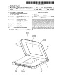
[0010] FIG. 1 is an assembly, perspective view of an electrical connector of the present invention, showing a retention plate positioned at an open position;
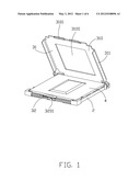
[0011] FIG. 2 is an exploded, perspective view of the electrical connector of FIG. 1;
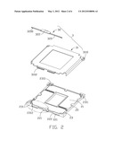
[0012] FIG. 3 is an enlarged view of the part labeled by a circle as shown in FIG. 2;
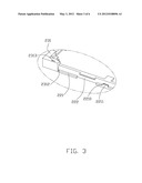
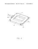
[0013] FIG. 4 is an assembly, perspective view of the electrical connector, showing the retention plate positioned at a closed position;
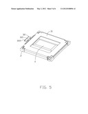
[0014] FIG. 5 is a schematic view of the electrical connector, showing a force exerted on a latch of the electrical connector; and
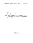
[0015] FIG. 6 is a cross-section view taken along line 6-6 of FIG. 4.
DETAILED DESCRIPTION OF THE INVENTION
[0016] Referring to FIG. 1 to FIG. 2, an electrical connector is used for electrically connected an electronic package 4 to a printed circuit board (not shown). The electrical connector includes an insulative housing 2, a plurality of contacts (not shown) received in the insulative housing 2, and a fastening assembly 3. The fastening assembly 3 comprises a retention plate 31 pivotally assembled in a rear end of the insulative housing 2 and a latch 32 assembled at a front end of the insulative housing 2.
[0017] Referring to FIG. 2 to FIG. 3, the insulative housing 2 is configured with a substantially rectangular structure and comprises a base 21 and a plurality of periphery walls 22 extending upward from the base 21 to define an inner cavity for receiving the electronic package 4. Four protrusions 23 are disposed at corners of the periphery walls 22 and each comprises two part sidewalls 231 perpendicular to each other. Each sidewalls 231 has a datum 2310 protruding toward the cavity for orientating the electronic package 4. The protrusions 23 are divided into two groups, and each group has the same configuration. A group of protrusions 23 positioned at the rear end of the insulative housing 2, and each protrusion 23 has a receiving hole 2311 to retain the retention plate 31.
[0018] Continue referring to FIG. 2 to FIG. 3, the insulative housing 2 has a plurality of ribs 221 which are disposed at an upper and a lower positions of the periphery walls 22 of the front end to define a channel 222 for receiving the latch 32. The protrusions 23 has mating holes 2312 extending horizontally and corresponding to the channel 222, and retention holes 2313 extending vertically and communicating with the mating holes 2312. One of the ribs 221 defined at a lower middle position of the periphery wall 22 has a block 2210 protruding upwardly and a flange 221 disposed at the outer sides of the block 2210. The upper position of the periphery wall 22 corresponding to the rib 221 with the block 2210 defines a gap to allow the latch 32 passing through.
[0019] Referring to FIGS. 1 and 2, the retention plate 310 includes a planar board 310 with an opening 3100 and a pair of sidewalls 311 extending downwardly at opposite sides of the board 310. A pair of tongues 3101 are extending downwardly and then horizontally from the front end of the planar board 310, and the horizontal part formed a supporting portion 3102. Each sidewall 311 has a bearing portion 3110 with a half-hoop shape to assembled in the receiving holes 2311 for allowing the retention plate 31 to rotate related to the insulative housing 2.
[0020] The latch 32 is made by a metal sheet and includes a long and narrow retention arm 320 received in the channel 222 of the insulative housing 2. The retention arm 320 defines a cutout 3201 disposed at a middle bottom for retain the block 2210 of the rib 221. A pair of grooves 3200 are defined near free ends of the retention arm 320 to be retained in the mating holes 2312 and the free ends of the retention arm 320 are assembled in the retention holes 2313. The latch 32 further includes a linking portion 321 extending upwardly from the retention arm 320 and a handle portion 322 extending horizontally from the linking portion 322. The linking portion is narrow than the handle portion 322 for allowing the bottom surface of two sides of the handle portion 322 to press the supporting portions 3102 of the tongues 3101. Referring to FIGS. 4 and 6, the handle portion 322 extends outwardly away from the receiving cavity of the insulative housing 2 and has a bottom surface locking and pressing the retention plate 31 and a top surface for operating by operators.
[0021] Referring to FIG. 5, the retention plate 310 is opened or closed by exerting an exerted force to the handle portion 322. Then the retention plate 310 is released since the handle portion 322 is rotated about the retention arm 320 by the force.
[0022] Although the present invention has been described with reference to particular embodiments, it is not to be construed as being limited thereto. Various alterations and modifications can be made to the embodiments without in any way departing from the scope or spirit of the present invention as defined in the appended claims.
User Contributions:
Comment about this patent or add new information about this topic:
Images included with this patent application:
 |  |
 |  |
 |  |
 |
| Similar patent applications: | |
| Date | Title |
|---|---|
| 2013-11-21 | Plug-connector with cap-holding mechanism |
| 2013-11-21 | Socket connector with signal contacts |
| 2013-11-21 | Connector with sensing component |
| 2013-11-21 | Multi-socketed electrical conduit apparatus |
| 2010-04-08 | Electrical termination |
| New patent applications in this class: | |
| Date | Title |
|---|---|
| 2019-05-16 | Anti-loose socket |
| 2019-05-16 | Mounting metal fitting, connector and connection system |
| 2017-08-17 | Connector receptacle having a shield |
| 2016-06-23 | Power connector |
| 2016-06-02 | Connector locking mechanism |
| New patent applications from these inventors: | |
| Date | Title |
|---|---|
| 2015-10-29 | Retention mmeber for positioning optical module |
| 2015-10-29 | Retention memeber for positioning optical module |
| 2015-10-08 | Retention module with protection cap |
| 2015-09-17 | Electrical connector with improved load plate |
| 2015-07-23 | Flippable electrical connector |
| Top Inventors for class "Electrical connectors" | |
| Rank | Inventor's name |
|---|---|
| 1 | Jerry Wu |
| 2 | Noah Montena |
| 3 | Qi-Sheng Zheng |
| 4 | Jun Chen |
| 5 | Norman R. Byrne |