Patent application title: Burner Assembly
Inventors:
Matthew James (St. Albans, GB)
Assignees:
Reckitt Benckiser (UK) Limited
IPC8 Class: AF23K500FI
USPC Class:
431 87
Class name: Timer, programmer, retarder or condition responsive control by manually started timer or retarder, or by time of day device of combustion initiating means, e.g., match striker, etc.
Publication date: 2012-04-26
Patent application number: 20120100494
Abstract:
A burner assembly comprising a burner element (8) at which gas is
combusted. A valve (2) allows selective release of gas from a source into
an expandable space (4) when the valve is opened. The space is
expanadable up to a fixed volume (3) against the action of a restoring
means. The space is arranged to contract under the action of the
restoring means to force gas out of the space and to the burner element.Claims:
1. A burner assembly comprising a burner element at which gas is
combusted, a gas source, a valve to allow selective release of gas from
the source, an expandable space to which gas from the gas source is
arranged to flow when the valve is opened, the space being expandable up
to a fixed volume against the action of a restoring means, the space
being arranged to contract under the action of the restoring means to
force gas out of the space and to the burner element.
2. An assembly according to claim 1, wherein the restoring means is a resilient member.
3. An assembly according to claim 2, wherein the resilient member is a balloon.
4. An assembly according to claim 1, wherein the valve is separate from the gas source.
5. An assembly according to claim 4, wherein the valve comprises a manually operable member which the user presses to initiate the release of gas.
6. An assembly according to claim 4, wherein the valve is a timed valve which is configured to close automatically at a predetermined time after it is opened.
7. An assembly according to claim 1, further comprising an ignition system which is activated by the manually operable member.
8. An assembly according to claim 1, wherein the burner is a catalytic burner.
9. An assembly according to claim 1, further comprising a heat distribution plate provided downstream of and spaced from the burner.
10. An assembly according to claim 9, wherein the plate is provided with a plurality of holes to promote air flow through the plate.
11. An assembly according to claim 10, wherein the holes furthest from the burner are larger than those closer to the burner.
Description:
[0001] The present invention relates to a burner assembly.
[0002] In our earlier application, PCT/GB2005/002735, we disclosed a heater for heating an active agent selected from cleaning, personal care, pesticidal and air care agents. The heater uses a gas burner in order to provide the heat.
[0003] Such a heater is particularly advantageous in that as it has an on-board power source, it offers the convenience and portability of a battery-based system. However, it is able to generate much higher levels of heat in a much shorter space of time than a battery-based system.
[0004] The present invention is directed to an improvement of such a heating system.
[0005] According to the present invention, there is provided a burner assembly, comprising a burner element at which gas is combusted, a gas source, a valve to allow selective release of gas from the source, an expandable space to which gas from the gas source is arranged to flow when the valve is opened, the space being expandable up to a fixed volume against the action of a restoring means, the space being arranged to contract under the action of the restoring means to force gas out of the space and to the burner element.
[0006] The expandable space and restoring means effectively act as a flow-smoothing device. In practice, gas leaving the gas source is not a consistent gas phase. The balloon smoothes this flow providing a constant flow to the burner thereby providing efficient and reliable combustion.
[0007] The expandable space may be provided, for example, by a piston in a cylinder. In this case, the restoring means may be a resilient member such as a spring against which the piston moves, or may be a closed gas volume, the pressure of which increases as the expandable space is filled with gas and decreases as the gas is expelled.
[0008] However, preferably, the expandable space'is provided by a resilient member such as a balloon housed within a rigid container which defines the fixed volume. Such an arrangement has the advantage that it can be implemented at low cost. The rigid container may be sealed and may be pressurised prior to balloon expansion to exert greater force on the balloon. Alternatively, it may have one or more small holes to provide less of a force on the balloon.
[0009] The valve may be an integral part of the gas source. In this case, an actuator is provided to depress the valve. The actuator may either move the valve element itself or may be configured to move the gas source itself while the valve is restrained thereby, effectively depressing the valve with respect to the gas source.
[0010] However, preferably, the valve is separate from the gas source. The valve preferably comprises a manually operable member which the user presses to initiate the release of gas. The valve is preferably a timed valve which is configured to close automatically at a pre-determined time after it is opened.
[0011] The burner may have an ignition system which is activated independently of the valve. However, preferably, the burner assembly has an ignition system which is activated by the manually operable member. As a safety feature, the manually operable member is preferably configured to stop the gas flow from the gas source prior to initiating ignition.
[0012] The burner may be any suitable burner, but is preferably a catalytic burner. In order to provide an even distribution of heat from the catalytic burner, a heat distribution plate is preferably provided downstream of and spaced from the catalytic burner. The plate is preferably provided with a plurality of holes to promote air flow through the plate and hence, enhance the heat distribution. Preferably, the holes furthest from the burner are larger than those closer to the burner as this encourages preferential air flow towards the periphery of the plate thereby ensuring even heat distribution.
[0013] An example of a burner in accordance with the present invention will now be described with reference to the accompanying drawings in which:
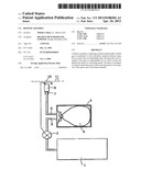
[0014] FIG. 1 is a schematic diagram of the burner assembly; and
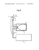
[0015] FIG. 2 is a schematic diagram of the same assembly in a second configuration.
[0016] The burner can be used to heat any active agent selected from the cleaning, personal care, pesticidal and air care agents. The full range of such agents is set out in PCT/032005/002735 and will not be repeated here as this invention is concerned with an improvement in the burner system, per se. However, the described burner of the particular example has been designed to heat wax strips which are useful in removing body hair.
[0017] The burner assembly comprises a source of combustible gas. In this case, a butane gas canister 1. Flow through the-gas canister is controlled by a valve 2. This is a timed valve which is designed to remain open for a fixed period following actuation as described in more detail below. Downstream of the valve 2 is a rigid chamber 3 in which an expandable balloon 4 is mounted. The expandable balloon receives gas from the canister 1 along inlet line 5 and expels gas along outlet line 6 as described below. The outlet line 6 leads via a flow restriction 7 to a catalytic burner 8 which is well-known in the art.
[0018] A piezo-electric ignition electrode 9 is positioned in close proximity to the burner 8 so that a spark is generated between the electrode 9 and burner 8 to ignite the gas. A metal flow distribution plate 10 is provided above and spaced from the burner 8. This plate has a plurality of holes 11 which are larger away from the burner 8 to ensure an even distribution of heat across the plate.
[0019] In use, a user will place, a wax strip on the plate 10 and will then operate the valve 2. This is done by depressing a manually depressible member (not shown) against the action of a spring. The manually depressible member has a helical groove which co-operates with a complimentary follower to cause it to rotate as it is depressed, the rotation opening the valve 2 to allow gas to flow from the burner 1 into the balloon 4 thereby expanding the balloon as shown in FIG. 2. Further rotation of the valve 2 causes the follower to pass beyond the end of the helical groove. At this time, the user feels a click so that they instinctively know how to release the button. This releases the manually operable member and the spring, then urges it back to its starting position. On its return stroke, the manually operable member closes the valve 2. The manually operable member has a lug which operates a piezo-electric spark generator in order to generate a spark at electrode 9 to ignite the gas. This is timed to be generated after the valve 2 has shut off the flow of gas from the gas canister 1. Typically, the time for which the valve 2 is open will be-very short (approximately 1 to 10 seconds) as a short burst of gas is all that is required to fill the balloon 4. Once full, the pressure generated by the resilience of the balloon 4 is sufficient to force the gas out of the balloon. The pressures in the system ensure that this gas is forced out of outlet line 6 rather than the inlet line 5. The gas 6 flows through the flow restriction 7 to the burner 8 where it is ignited by the spark to generate heat. Typically, the rigid chamber 3 and balloon 4 have a volume of 1 to 40 cm3 and are designed to provide a flow of gas to the burner for around 1 to 60 seconds. In one particular, example, the button is pressed filling the balloon in 0.5 seconds, 0.1 seconds later the valve is closed, and 0.1 seconds after that the ignition produces a spark. The gas finishes burning 16 seconds after the button is pressed.
[0020] In alternative embodiments, the balloon 4 may be replaced by a piston which, as it is displaced to the right as shown in FIG. 1, bears against a spring or compresses gas to generate a restoring force on the piston.
[0021] As an alternative to the valve 2, an actuation mechanism may be used to depress a valve in the canister 1 either by directly pressing the valve stem, or by moving the canister 1 against a fixed stop which contacts the valve stem and causes it to be depressed into the canister 1 upon further movement of the canister 1.
User Contributions:
Comment about this patent or add new information about this topic:
| People who visited this patent also read: | |
| Patent application number | Title |
|---|---|
| 20220216830 | MIXER AND SEMICONDUCTOR DEVICE |
| 20220216829 | ADAPTIVE MICROPHONICS NOISE CANCELLATION |
| 20220216828 | COMPLEX ENERGY GENERATION DEVICE USING SUNLIGHT AND SOLAR HEAT |
| 20220216827 | COMPLEX ENERGY GENERATION DEVICE USING SUNLIGHT AND SOLAR HEAT |
| 20220216826 | Photovoltaic Panel Cleaning System |
Images included with this patent application:
 |  |
 |
| Similar patent applications: | |
| Date | Title |
|---|---|
| 2008-11-13 | Coal burner assembly |
| 2008-11-13 | Burner assembly |
| New patent applications in this class: | |
| Date | Title |
|---|---|
| 2012-05-10 | Device for controlling gas supply to a burner |
| Top Inventors for class "Combustion" | |
| Rank | Inventor's name |
|---|---|
| 1 | Christopher A. Wiklof |
| 2 | Igor A. Krichtafovitch |
| 3 | Joseph Colannino |
| 4 | David Deng |
| 5 | Robert E. Breidenthal |