Patent application title: TURBOCHARGER TURBINE
Inventors:
Thomas Ramb (Worms, DE)
Thomas Ramb (Worms, DE)
Assignees:
BorgWarner Inc.
IPC8 Class: AF01D1700FI
USPC Class:
415145
Class name: Rotary kinetic fluid motors or pumps working fluid bypass selectively adjustable vane or working fluid control for bypass
Publication date: 2012-04-26
Patent application number: 20120099965
Abstract:
A turbocharger turbine which has a wastegate slide sleeve (8), which is
provided in a wastegate arrangement (5) and which closes off the
wastegate duct, as a shut-off element. The wastegate arrangement (5)
comprises a bypass duct (6) which runs in the turbine housing (2); a
wastegate duct (7) which runs in the turbine housing (2) to the turbine
housing outlet (4) and which is connected via the bypass duct (6) to the
turbine housing inlet (3); and a shut-off element (8) which is arranged
in the turbine housing (2). The shut-off element (8) is provided to open
and close the wastegate duct (7) and can be moved by means of an
actuating device (9) into an open position and closed position.Claims:
1. A turbocharger turbine (1), having a turbine housing (2) in which a
turbine wheel (10) is arranged so as to be rotatable about a turbine
housing axis (L) and which has a turbine housing inlet (3) and a turbine
housing outlet (4); and having a wastegate arrangement (5) which has: a
bypass duct (6) which runs in the turbine housing (2), a wastegate duct
(7) which runs in the turbine housing (2) to the turbine housing outlet
(4) and which is connected via the bypass duct (6) to the turbine housing
inlet (3); and a shut-off element (8) which is arranged in the turbine
housing (2) and which, in order to open and close the wastegate duct (7),
can be moved by means of an actuating device (9) into an open position
and closed position, wherein the shut-off element is designed as a slide
sleeve (8).
2. The turbine as claimed in claim 1, wherein the bypass duct (6) opens out into an annular chamber (11) which is arranged in the turbine housing (2) upstream of the wastegate duct (7) as viewed in the flow direction of the exhaust gases conducted around the turbine wheel (10).
3. The turbine as claimed in claim 1, wherein the slide sleeve (8) is guided, at its inner surface (12) which points toward the turbine housing axis (L), by means of a bearing sleeve (13) which is fixed in the turbine housing (2).
4. The turbine as claimed in claim 1, wherein the slide sleeve (8) is guided, at its outer surface (14) pointing away from the turbine housing axis (L), by means of a bearing sleeve (15) which is fixed in the turbine housing (2).
5. The turbine as claimed in claim 1, wherein the bearing sleeve (15) extends into the region of the turbine housing wall (19) and is provided with at least one opening (16) in said region.
6. The turbine as claimed in claim 1, wherein the turbine housing (2) is provided with at least two channels (17, 18) which are assigned in each case one bypass duct (6; 6') and one annular chamber segment (11; 11').
7. The turbine as claimed in claim 6, wherein a bearing sleeve (15) is provided with openings (16; 16') assigned to annular chambers (11; 11').
8. The turbine as claimed in claim 1, wherein the slide sleeve (8) is guided, in the closed position, as far as a point at which it abuts against the turbine housing wall (19).
9. The turbine as claimed in claim 1, wherein the wastegate duct (7) generates an axial flow component.
10. The turbine as claimed in claim 1, wherein the cross-sectional area of the wastegate duct (7) is dimensioned so as to create an ejector effect with high flow speeds.
11. The turbine as claimed in claim 1, wherein the axis of the slide sleeve (8) is inclined in relation to the turbine housing axis (L).
12. The turbine as claimed in claim 1, wherein the actuating device (9) is designed as an actuating fork.
13. The turbine as claimed in claim 1, wherein the actuating device (9) is designed as a lever which can be moved by means of a guide slot/groove arrangement.
Description:
[0001] The invention relates to a turbocharger turbine according to the
preamble of claim 1.
[0002] In supercharged internal combustion engines which use an exhaust-gas turbocharger, the latter is often provided with a wastegate. An exhaust-gas turbocharger having a wastegate is known from EP 1 256 703 B1.
[0003] In the present prior art, the regulation of a wastegate arrangement takes place by means of the regulating valve or regulating flap. The latter is actuated by means of a control capsule or another actuator, such as for example an electric actuator, and remains closed for as long as no bypass quantity is desired. To be able to further reduce the exhaust-gas back pressure with ever-increasing throughput, wastegate cross sections in particular in spark-ignition engines are becoming ever larger. As a result, the force with which the flap must be held closed also increases. There are thus often resulting installation space problems as a result of excessively large control capsules or with available electric actuators.
[0004] It is therefore an object of the present invention to provide a turbine of the type specified in the preamble of claim 1 whose wastegate can be regulated and held closed in a reliable and simple manner even for large wastegate cross sections.
[0005] Said object is achieved by means of the features of claim 1.
[0006] Subclaims 2 to 9 relate to further advantageous refinements of the invention.
[0007] According to the invention, a shut-off element in the form of a wastegate slide is provided which can open and close the wastegate duct. The wastegate slide is provided with a suitable actuating device for this purpose.
[0008] According to the invention, the slide as a sleeve can be guided, at its inner or outer circumferential surface, by means of a bearing sleeve which is fixed in the turbine housing. In particular, the wastegate arrangement according to the invention can be used for all types of turbine housings (single-channel, multi-channel, double-flow) and can be produced at low cost and installed with a minimal spatial requirement.
[0009] Further details, advantages and features of the present invention will emerge from the following description of exemplary embodiments on the basis of the appended drawing, in which:
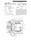
[0010] FIG. 1 shows a simplified sectional view of a first embodiment of the exhaust-gas turbocharger with a wastegate slide sleeve mounted at the inside;
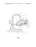
[0011] FIG. 2 shows a simplified sectional view of a second embodiment of the exhaust-gas turbocharger with a wastegate slide sleeve mounted at the outside;
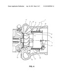
[0012] FIG. 3 shows a simplified sectional view of a wastegate slide sleeve which is guided in a bearing sleeve which extends as far as the turbine housing wall;
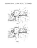
[0013] FIG. 4 shows a simplified sectional illustration of a two-channel exhaust-gas turbocharger with separate bypass guidance.
[0014] The turbocharger turbine 1 illustrated in FIG. 1 has, according to a first embodiment, a turbine housing 2 and a wastegate arrangement 5. The turbine housing 2, in which a turbine wheel 10 is arranged so as to be rotatable about a turbine housing axis L, comprises a turbine housing inlet 3 and a turbine housing outlet 4.
[0015] The wastegate arrangement 5 comprises a bypass duct 6, which runs in the turbine housing 2, and a wastegate duct 7 which runs to the turbine housing outlet 4 and which is connected via the bypass duct 6 to the turbine housing inlet 3. Furthermore, the wastegate arrangement 5 comprises a shut-off element 8 which is arranged in the turbine housing 2 and which, in order to open and close the wastegate duct 7, can be moved by means of an actuating device 9 into an open position and closed position. Said shut-off element is designed as an axially movable annular wastegate slide sleeve 8.
[0016] The slide sleeve 8 is guided, at its inner surface 12 pointing toward the turbine housing axis L, by means of a bearing sleeve 13 which is fixed to the turbine housing 2.
[0017] The bearing housing 13 projects as far as the turbine housing wall 19 and has openings 16 which open out into a wastegate duct 7. In the closed position, the slide sleeve 8 does not generate any axial sealing action with the turbine housing wall 19, such that no high closing forces are required.
[0018] Targeted guidance of the bypass flow to the exhaust-gas flow emerging from the turbine wheel is obtained by means of the shaping of the wastegate duct 7. This results in good thermal mixing of the two flows. Furthermore, by means of corresponding selection of the duct cross-sectional areas, it is possible to obtain a pressure reduction at the turbine wheel outlet by means of high bypass flow speeds (ejector effect).
[0019] In the second embodiment according to FIG. 2, in which all the features corresponding to FIG. 1 are provided with the same reference symbols, the slide sleeve 8 is guided, at its outer surface 14 pointing away from the turbine housing axis L, by means of a bearing sleeve 15 which is fixed in the turbine housing 2. Here, the bearing sleeve 15 does not extend as far as the turbine housing wall 19. The remaining spacing corresponds to the opening 16, and the slide sleeve 8 seals off against the turbine housing wall 19 in the closed position.
[0020] It can also be seen from FIG. 3 that, in said embodiment, the bearing sleeve 15 extends into the region of the turbine housing wall 19 and is provided with a least one opening 16 in the region of the wastegate duct 7. As a result of said opening 16, the axial slide pressing force for sealing against the turbine housing wall 19 by means of the bearing sleeve 15 can be eliminated. The axial force for moving the slide can accordingly be selected to be only so high that the slide opens and closes the opening 16 of the bearing sleeve 15, as in FIG. 1.
[0021] As illustrated in FIG. 4, the turbine housing 2 is provided in this embodiment with two channels 17, 18 which are assigned in each case one bypass duct 6 and 6' and one annular chamber segment 11 and 11'. Here, the turbine housing 2 may also have more than two channels.
[0022] Openings 16 and 16' are provided in the bearing sleeve 15', which openings 16 and 16' are assigned to the annular chamber segments 11 and 11'.
[0023] Furthermore, the actuating device 9 may be designed as an actuating fork or as a lever which can be moved by means of a guide slot and groove arrangement.
[0024] To supplement the above disclosure, reference is made explicitly to the diagrammatic illustration of the invention in FIGS. 1 to 4.
LIST OF REFERENCE SYMBOLS
[0025] 1 Turbocharger turbine [0026] 2 Turbine housing [0027] 3 Turbine housing inlet [0028] 4 Turbine housing outlet [0029] 5 Wastegate arrangement [0030] 6; 6' Bypass duct [0031] 7 Wastegate duct [0032] 8 Shut-off element [0033] 8 Slide sleeve [0034] 9 Actuating device [0035] 10 Turbine wheel [0036] 11; 11' Annular chamber or annular chamber segment [0037] 12 Inner surface [0038] 13, 15, 15' Bearing sleeve [0039] 14 Outer surface [0040] 16; 16' Opening [0041] 17, 18 Channels [0042] 19 Turbine housing wall [0043] L Turbine housing axis
User Contributions:
Comment about this patent or add new information about this topic:
Images included with this patent application:
 |  |
 |  |
| Similar patent applications: | |
| Date | Title |
|---|---|
| 2010-08-05 | Turbocharger with variable turbine geometry |
| 2012-04-26 | Turbocharger turbine |
| 2012-10-04 | Turbocharger with variable turbine geometry |
| 2009-08-13 | Turbocharger shaft bearing system |
| 2011-07-14 | Turbocharger and adjustment ring therefor |
| New patent applications in this class: | |
| Date | Title |
|---|---|
| 2019-05-16 | Gas turbine engine with mid-compressor bleed |
| 2018-01-25 | Exhaust gas turbocharger |
| 2016-07-14 | Systems and methods controlling fan pressure ratios |
| 2016-06-09 | Turbocharger combining axial flow turbine with a compressor stage utilizing active casing treatment |
| 2016-06-09 | Turbine engine assembly and method of manufacturing |
| New patent applications from these inventors: | |
| Date | Title |
|---|---|
| 2015-05-14 | Exhaust-gas turbocharger |
| 2015-04-30 | Exhaust-gas turbocharger |
| 2015-03-26 | Exhaust-gas turbocharger |
| 2014-06-05 | Exhaust-gas turbocharger |
| 2014-06-05 | Turbocharger |
| Top Inventors for class "Rotary kinetic fluid motors or pumps" | |
| Rank | Inventor's name |
|---|---|
| 1 | Gabriel L. Suciu |
| 2 | Frederick M. Schwarz |
| 3 | United Technologies Corporation |
| 4 | Brian D. Merry |
| 5 | Craig M. Beers |