Patent application title: Polymeric Bags
Inventors:
Michael A. Ross (Dallas, TX, US)
Michael A. Ross (Dallas, TX, US)
Assignees:
Poly-America, L.P.
IPC8 Class: AB65D3328FI
USPC Class:
383 75
Class name: Gathered bag mouth including drawstring-type securing element in bag hem
Publication date: 2012-04-26
Patent application number: 20120099807
Abstract:
The present invention is directed to a polymeric bag having an elastic
portion extending generally across the width of the bag, wherein the
elastic portion has a lower modulus of elasticity than the remainder of
the bag. The bag is primarily comprised of a first polymer blend while
the elastic portion is comprised of a second polymer blend.Claims:
1. A thermoplastic bag comprising: a first panel and a second panel, the
first panel and second panel joined along a first side edge, a second
side edge, and a bottom edge, a top edge of the first panel and second
panel defining an upper opening of the bag, the first panel being
substantially comprised of a first polymer blend, an elastic portion of
the first panel being comprised of a second polymer blend, the elastic
portion of the first panel extending across a width of the first panel,
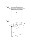
and the second polymer blend having a lower modulus of elasticity than
the first polymer blend.
2. The thermoplastic bag of claim 1, further comprising: the first polymer blend comprises at least 80% LLDPE, and the second polymer blend comprising less than 80% LLPDE.
3. The thermoplastic bag of claim 1, further comprising: the second polymer blend comprising at least 20% of polymers selected from the group consisting of ethylene-vinyl acetate (EVA), ethylene-acrylic acid (EAA), very low density polyethylene (VLDPE), ultra low density polyethylene (ULDPE), and a combination thereof.
4. The thermoplastic bag of claim 1, further comprising: the second polymer blend comprising at least 50% of polymers selected from the group consisting of ethylene-vinyl acetate (EVA), ethylene-acrylic acid (EAA), very low density polyethylene (VLDPE), and ultra low density polyethylene (ULDPE), and a combination thereof.
5. The thermoplastic bag of claim 1, further comprising: a drawstring disposed within a hem of the first panel, the elastic portion of the first panel including the hem of the first panel.
6. The thermoplastic bag of claim 5, further comprising: the drawstring is an elastic drawstring.
7. The thermoplastic bag of claim 1, further comprising: the elastic portion of the first panel is proximate the upper opening of the bag.
8. The thermoplastic bag of claim 1, further comprising: a first flap and a second flap, the first flap and the second flap located along the upper opening of the bag.
9. The thermoplastic bag of claim 8, further comprising: the elastic portion of the first panel is proximate the first flap.
10. The thermoplastic bag of claim 8, further comprising: the elastic portion of the first panel includes at least a part of the first flap.
Description:
CROSS-REFERENCE TO RELATED APPLICATIONS
[0001] Not applicable.
BACKGROUND OF THE INVENTION
[0002] 1. Field of the Invention
[0003] The present invention relates to improvements in the construction and manufacture of polymeric bags. In particular, the present invention relates to improvements to trash bags.
[0004] 2. Description of the Related Art
[0005] Polymeric bags are ubiquitous in modern society and are available in countless combinations of varying capacities, thicknesses, dimensions and colors. The bags are available for numerous applications including typical consumer applications such as long-term storage, food storage, and trash collection. Like many other consumer products, increased demand and new technology has driven innovations in polymeric bags improving the utility and performance of such bags. The present invention is an innovation of particular relevance to polymeric bags used for trash collection.
[0006] Polymeric bags are manufactured from polymeric film produced using one of several manufacturing techniques that are well-known in the art. However, the two most common manufacturing methods for creating polymeric film are blown-film extrusion and cast-film extrusion. Both blown-film extrusion and cast-film extrusion offer certain advantages versus the other. The ultimate selection of a method of manufacture is often driven by considerations such as the desired properties for the final product as well as by financial considerations.
[0007] In both blown-film extrusion and cast-film extrusion, an extruder is used to push molten polymeric material through a die. In the case of blown-film extrusion, the film during processing is tubular in shape. In cast-film extrusion, the film during processing is substantially flat. Certain dies also allow for the manufacture of polymeric films having multiple layers co-extruded through a single die. An early die designed to produce multi-layer blown-film tubes is described in U.S. Pat. No. 4,185,954 entitled Die for Extruding Tubes Composed of Plurality of Layers. Furthermore, other types of co-extrusion dies are available which allow for different polymer blends to be extruded through a single die to provide distinct sections across the width, or circumference, of the extruded film. Such dies might be used with polymer blends having different color additives to provide stripes in the extruded blown-film.
[0008] As previously stated, the present invention relates to polymeric trash bags, which are available in several popular configurations such as drawstring trash bags and wave-cut trash bags, the latter of which have two or more flaps extending from the top of the bag. Both drawstring and wave-cut trash bags are popular among consumers and, given their popularity, recent innovations have attempted to improve the bags' performance.
[0009] One common complaint, which is applicable to many different types of trash bags, revolves around the tendency of the trash bag to fall into the trash can during use. Specifically, during use of the product, the top of the trash bag, which is placed over the top of the can, often has a tendency to fall into the trash can as the weight of the trash pulls the bag downward into the can.
[0010] To address this issue, trash bag manufacturers have come up with several methods intended to enhance the ability of the bag to "grip" the outside of the trash can near the top of the trash can. With respect to drawstring trash bags, elastic drawstrings have been introduced which stretch outward and retract in order to grip the outside of a trash receptacle. However, the physical properties and strength of the panels comprising the trash bags, specifically the area near the top of the bag at or around the hem area, can make it difficult to stretch the mouth of the bag over the perimeter of the trash receptacle.
[0011] One prior art attempt to address this problem is to provide perforations or notches near the upper corners of the bag thereby allowing the ends of an elastic drawstring to be separated from the bag proper and stretched over and around the upper opening of a trash receptacle. However, the perforations or notches result in large openings at the top of the bag when it is closed. Additionally, when compared with traditional drawstring trash bags, the perforations and/or notches in the bag can increase the risk that tears will propagate away from the cutouts when stress is placed on the bag.
[0012] In view of the foregoing, it would be desirable to provide a trash bag that is easier to extend over the upper opening of a trash can, keeps the structural integrity of the bag intact, and overcomes challenges of the prior art. Additionally, it would also be desirable to provide a trash bag that effectively grips trash cans. The present invention addresses these and other needs.
SUMMARY OF THE INVENTION
[0013] In one embodiment of the present invention, a thermoplastic bag comprises a first panel and a second panel. The first panel and second panel are joined along a first side edge, a second side edge, and a bottom edge. A top edge of the first panel and second panel defines an upper opening of the bag. The first panel is substantially comprised of a first polymer blend with an elastic portion of the first panel comprised of a second polymer blend. The elastic portion of the first panel extends across a width of the first panel. The second polymer blend has a lower modulus of elasticity than the first polymer blend.
[0014] It is contemplated that the present invention may be utilized in ways that are not fully described or set forth herein. The present invention is intended to encompass these additional uses to the extent such uses are not contradicted by the appended claims. Therefore, the present invention should be given the broadest reasonable interpretation in view of the present disclosure, the accompanying figures, and the appended claims.
BRIEF DESCRIPTION OF THE RELATED DRAWINGS
[0015] A full and complete understanding of the present invention may be obtained by reference to the detailed description of the present invention and certain embodiments when viewed with reference to the accompanying drawings. The drawings can be briefly described as follows.
[0016] FIG. 1 provides a perspective view of a first embodiment of the present invention.
[0017] FIG. 2 provides an elevation view of a panel used to construct the first embodiment of the present invention.
[0018] FIG. 3 provides a perspective view of a second embodiment of the present invention.
[0019] FIG. 4 provides a perspective view of a third embodiment of the present invention.
DETAILED DESCRIPTION OF THE INVENTION
[0020] The present disclosure illustrates several embodiments of the present invention. It is not intended to provide an illustration or encompass all embodiments contemplated by the present invention. In view of the disclosure of the present invention contained herein, a person having ordinary skill in the art will recognize that innumerable modifications and insubstantial changes may be incorporated or otherwise included within the present invention without diverging from the spirit of the invention. Therefore, it is understood that the present invention is not limited to those embodiments disclosed herein. The appended claims are intended to more fully and accurately encompass the invention to the fullest extent possible, but it is fully appreciated that certain limitations on the use of particular terms are not intended to conclusively limit the scope of protection.
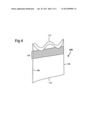
[0021] Referring initially to FIG. 1, a perspective view of drawstring trash bag 100 is shown according to one embodiment of the present invention. The drawstring trash bag comprises a first panel 102 and a second panel 104, each panel being substantially rectangular in shape. The first panel 102 and second panel 104 are coupled along a first side edge 106, a second side edge 108, and a bottom edge 110 of the respective panels 102 and 104. In some embodiments, the first panel 102 and second panel 104 may be formed from a single piece of polymeric film, folded to define a bottom edge 110 and sealed along the first side edge 106 and second side edge 108.
[0022] The unsealed top edge 112 of the respective panels 102 and 104 defines the upper opening of the drawstring trash bag. A pair of drawstrings 140 are disposed within hems 142 located proximate the top edge 112 of the respective first panel 102 and second panel 104. The drawstrings are generally loose within the hems 142 and sealed near the upper corners of the drawstring trash bag 100 by short seals 120 and 122. Therefore, when the drawstrings 140 are pulled through the drawstring cutouts 144 of the bag 100, the respective upper corners of the bag 100 are pulled together, facilitating closure of the bag.
[0023] In the depicted embodiment of FIG. 1, the panels 102 and 104 of the drawstring trash bag 100 are primarily comprised of a polymer blend which generally comprises linear low density polyethylene (LLDPE) although other polyethylenes may be utilized as the primary component such as high density polyethylene (HDPE) or low density polyethylene (LDPE). Typically, the LLDPE comprises at least 80% of the polymer blend. The remaining 20% of the polymer blend may comprise additives to provide color for the final product, increased resistance to blocking, odor control, or other properties.
[0024] A modified polymer blend is used for an elastic portion 150 of the drawstring trash bag 100. The elastic portion 150 generally extends across the width of the drawstring trash bag 100 and may generally encompass the hems 142 and may also encompass a small area of the drawstring trash bag 100 below the hems 142. The modified polymer blend has a lower modulus of elasticity than the remainder of the panels 102 and 104 facilitating the elastic portion 150 of the drawstring trash bag 100 to be stretched over the outside of a trash receptacle. Additionally, the modified blend may provide greater elastic recovery improving the grip of the drawstring trash bag 100 on the outside of the trash receptacle after being placed over it while keeping the structural integrity of the bag intact. It is contemplated that several different polymers may be used in the elastic portion 150 including, but not limited to, ethylene-vinyl acetate (EVA), ethylene-acrylic acid (EAA), very low density polyethylene (VLDPE), and ultra low density polyethylene (ULDPE). In some embodiments of the present invention, the modified blend may comprise at least 20% ULDPE or VLDPE. However, in certain preferred embodiments, the modified polymer blend has at least 50% ULDPE or VLDPE.
[0025] Referring now to FIG. 2, first panel 102 is depicted to better illustrate the first panel 102 made with a first polymer blend and the elastic portion 150 made with a second, modified polymer blend. As can be seen, elastic portion 150 of the first panel 102 encompasses the entire area of the hems 142 and extends slightly below the hem 142 as well.
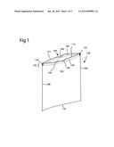
[0026] Referring now to FIG. 3, another embodiment of the present invention is depicted. The embodiment depicted in FIG. 3 is an improved drawstring bag 300 similar to the drawstring trash bag 100 of FIG. 1. However, in this improved drawstring trash bag 300, a first inner short seal 320 and a second inner short seal 322 seal the drawstrings 140 and panels 102 and 104 together effectively reducing the width of the upper opening of the improved drawstring bag 300.
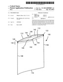
[0027] Referring now to FIG. 4, a wave-cut bag 400 is depicted with four flaps along the top edge 112 of the bag. The flaps can be used to tie the bag. An elastic portion 150 of the wave-cut bag 400 depicted uses the modified polymer blend previously described and is shown in dashed line for illustrative purposes. Like the earlier depicted embodiments, the modified polymer blend may have a lower modulus of elasticity.
[0028] As previously noted, the specific embodiments depicted herein are not intended to limit the scope of the present invention. Indeed, it is contemplated that any number of different embodiments may be utilized without diverging from the spirit of the invention. Therefore, the appended claims are intended to more fully encompass the full scope of the present invention.
User Contributions:
Comment about this patent or add new information about this topic:
Images included with this patent application:
 |  |
 |  |
| Similar patent applications: | |
| Date | Title |
|---|---|
| 2012-09-06 | Polymeric bag with elastic drawtape |
| 2012-04-05 | Drawstring polymeric bag |
| New patent applications in this class: | |
| Date | Title |
|---|---|
| 2016-04-07 | Draw tape bag |
| 2016-02-18 | Bag |
| 2016-02-04 | Extended hem fold drawstring bag |
| 2015-12-03 | Plastic liner bag with drawstring |
| 2015-02-19 | Fabric wrap |
| New patent applications from these inventors: | |
| Date | Title |
|---|---|
| 2012-05-17 | Bags |
| 2011-03-17 | Apparatus and method for an elastic drawstring trash compactor bag |
| 2010-09-30 | Elastic drawstring trash bag |
| 2010-05-06 | Reduced opening elastic drawstring bag |
| Top Inventors for class "Flexible bags" | |
| Rank | Inventor's name |
|---|---|
| 1 | Shaun T. Broering |
| 2 | Robert R. Turvey |
| 3 | Brian C. Dais |
| 4 | Bryan L. Ackerman |
| 5 | Robert W. Fraser |