Patent application title: PERMANENT MAGNET ROTOR FOR ELECTRIC MACHINE
Inventors:
Michael D. Bradfield (Anderson, IN, US)
Michael D. Bradfield (Anderson, IN, US)
Assignees:
REMY TECHNOLOGIES, L.L.C.
IPC8 Class: AH02K922FI
USPC Class:
310 52
Class name: Dynamoelectric rotary cooling or fluid contact
Publication date: 2012-03-15
Patent application number: 20120062054
Abstract:
A permanent magnet rotor assembly for an electric machine includes a
rotor core including one or more axially-extending openings and one or
more permanent magnets located in the one or more axially-extending
openings defining one or more gaps between the one or more permanent
magnets and the one or more axially-extending openings. One or more
thermally-conductive bars are located in the one or more gaps to transfer
thermal energy from an interior of the rotor assembly toward an axial end
of the rotor assembly.Claims:
1. A permanent magnet rotor assembly for an electric machine comprising:
a rotor core including one or more axially-extending openings; one or
more permanent magnets disposed in the one or more axially-extending
openings defining one or more gaps between the one or more permanent
magnets and the one or more axially-extending openings; and one or more
thermally-conductive bars disposed in the one or more gaps to transfer
thermal energy from an interior of the rotor assembly toward an axial end
of the rotor assembly.
2. The rotor assembly of claim 1, wherein the one or more conductive bars are disposed between the one or more permanent magnets and a wall of the axially-extending opening.
3. The rotor assembly of claim 1, wherein the one or more axially-extending openings have a closed cross-section.
4. The rotor assembly of claim 3, wherein the closed cross-section is substantially oval.
5. The rotor assembly of claim 1, wherein the one or more axially-extending openings extend from a first axial end of the rotor core to a second axial end of the rotor core.
6. The rotor assembly of claim 1, wherein the one or more thermally-conductive bars are formed from an aluminum or copper based material.
7. The rotor assembly of claim 1, wherein the one or more thermally-conductive bars are formed from a powdered metal material.
8. The rotor assembly of claim 7, wherein particles of the powdered metal are individually coated with a magnetically and/or electrically insulative material.
9. An electric machine comprising: a stator; a rotor assembly disposed at a central axis of the electric machine and interactive with the stator, the rotor assembly including: a rotor core including one or more axially-extending openings; one or more permanent magnets disposed in the one or more axially-extending openings defining one or more gaps between the one or more permanent magnets and the one or more axially-extending openings; and one or more thermally-conductive bars disposed in the one or more gaps to transfer thermal energy from an interior of the rotor assembly toward an axial end of the rotor assembly.
10. The electric machine of claim 9, wherein the one or more conductive bars are disposed between the one or more permanent magnets and a wall of the axially-extending opening.
11. The electric machine of claim 9, wherein the one or more axially-extending openings have a closed cross-section.
12. The electric machine of claim 11, wherein the closed cross-section is substantially oval.
13. The electric machine of claim 9, wherein the one or more axially-extending openings extend from a first axial end of the rotor core to a second axial end of the rotor core.
14. The electric machine of claim 9, wherein the one or more thermally-conductive bars are formed from an aluminum or copper based material.
15. The electric machine of claim 9, wherein the one or more thermally-conductive bars are formed from a powdered metal material.
16. The electric machine of claim 15, wherein particles of the powdered metal are individually coated with a magnetically and/or electrically insulative material.
17. The electric machine of claim 9, wherein the electric machine is a hybrid motor.
18. A method of cooling a rotor of a permanent magnet electric machine comprising: disposing one or more thermally conductive bars in one or more axially-extending openings in a rotor core; transferring thermal energy to the one or more thermally conductive bars from the rotor; and transferring the thermal energy along a length of the one or more conductive bars to an axial end of the rotor; and dissipating the thermal energy from the axial end of the rotor.
Description:
BACKGROUND
[0001] The subject matter disclosed herein relates generally to electric machines. More specifically, the subject disclosure relates to permanent magnet rotor construction for electric machines.
[0002] Typical permanent magnet rotors used in electric machines, such as hybrid motors, include slots extending through a rotor lamination stack to receive the permanent magnets. The slots are typically oval in shape, and receive rectangular magnets, so there are gaps between each slot and each magnet. This gap is then injected molded with nylon or filled with an epoxy or varnish material to fill the gap.
[0003] Cooling the permanent magnets in such a rotor is a challenge. Operation of the rotor at elevated temperatures causes degradation in magnet performance, and even demagnetization of the magnets resulting in failure of the motor.
BRIEF DESCRIPTION
[0004] A permanent magnet rotor assembly for an electric machine includes a rotor core including one or more axially-extending openings and one or more permanent magnets located in the one or more axially-extending openings defining one or more gaps between the one or more permanent magnets and the one or more axially-extending openings. One or more thermally-conductive bars are located in the one or more gaps to transfer thermal energy from an interior of the rotor assembly toward an axial end of the rotor assembly.
[0005] An electric machine for a motor vehicle includes a stator, and a rotor assembly located at a central axis of the electric machine and interactive with the stator. The rotor assembly includes a rotor core having one or more axially-extending openings and one or more permanent magnets located in the one or more axially-extending openings defining one or more gaps between the one or more permanent magnets and the one or more axially-extending openings. One or more thermally-conductive bars are located in the one or more gaps to transfer thermal energy from an interior of the rotor assembly toward an axial end of the rotor assembly.
[0006] A method of cooling a rotor of a permanent magnet electric machine includes locating one or more thermally conductive bars in one or more axially-extending openings in a rotor core. Thermal energy is transferred to the one or more thermally conductive bars from the rotor and is transferred along a length of the one or more conductive bars to an axial end of the rotor. The thermal energy is dissipated from the axial end of the rotor.
BRIEF DESCRIPTION OF THE DRAWINGS
[0007] FIG. 1 is a cross-sectional view of an embodiment of a permanent magnet electric machine;
[0008] FIG. 2 is a cross-sectional view of another embodiment of a permanent magnet electric machine; and
[0009] FIG. 3 is a partial perspective view of an embodiment of a rotor of a permanent magnet electric machine.
The detailed description explains embodiments of the invention, together with advantages and features, by way of example with reference to the drawings.
DETAILED DESCRIPTION
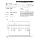
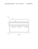
[0010] Shown in FIG. 1 is an embodiment of an electric machine 10. In some embodiments, the electric machine 10 is a motor for a hybrid vehicle or an electric vehicle. The electric machine 10 includes a rotor 12 rotably secured about a central axis 14 of the electric machine 10. A stator 16 is located to be interactive with the rotor 12. The rotor 12 includes a rotor core 18, which in some embodiments is formed from a plurality of rotor laminations 20 stacked along the axis 14. The rotor laminations 20 are typically formed from a metallic material, for example, steel. The rotor core 18 includes a plurality of axially-extending magnet openings 22. The magnet openings 22 may have a closed cross-section or, as shown in FIG. 2, may have a cross-section which breaks through an outer perimetrical surface 24 of the rotor core 18.
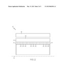
[0011] Referring now to FIG. 3, a plurality of rotor magnets 26 are located in the plurality of magnet openings 22. In the embodiment of FIG. 3, one rotor magnet 26 is located in each magnet opening 22, but it is to be appreciated any suitable number of rotor magnets 26, for example, two or more rotor magnets 26, may be located in the magnet openings 22. The rotor magnets 26 extend from a first axial end 28 of the rotor core 18 to a second axial end 50 of the rotor core 18, and have a cross-section such that when the rotor magnet 26 is inserted into the magnet opening 22, there is a gap 30 between a lateral end 32 of the rotor magnet 26 and a magnet opening wall 34. In some embodiments, the gap 30 is a result of the rotor magnet 26 having a rectangular cross-section and the magnet opening 22 having an oval or elliptical cross-section. The gap 30 is included by design and serves both magnetic and structural purposes. Magnetically, the gap aids in preventing short-circuiting of magnetic flux from the rotor magnet 26. The rotor magnets 26 are magnetized such that a direction of magnetization is along the lateral ends 32 of the rotor magnets 26, thus without the presence of the gap 30, a short circuit path would exist for the magnetic flux. Additionally, the gap 30 between the rotor laminations 20 and the rotor magnets 26 at the lateral ends 32 aids in preventing demagnetization of the rotor magnets 26 during operation of the electric machine 10. Further, rounded ends of the magnet opening 22 reduce stress concentrations in the rotor laminations 20 compared to magnet openings 22 having sharp corners.
[0012] A thermally conductive bar 36 extending a length of the magnet opening 22 is installed in the gap 30. In some embodiments, the conductive bar 36 is formed from an aluminum or copper based material. An aluminum based conductive bar 36 has a thermal conductivity about 4 times that of the steel rotor laminations 20, while a copper based conductive bar 36 has a thermal conductivity about 8 times that of the rotor laminations 20. In some embodiments, the conductive bar 36 is a single, solid piece of material, while in other embodiments, the conductive bar 36 may be a tubular form or other hollow shape. Further the conductive bar 36 may comprise more than one piece of material, or may be formed of more than one type of material. For example, the conductive bar 36 may be a layered structure including layers of conductive materials arranged to form the conductive bar 36. It is to be appreciated that the conductive bar 36 structures described herein are merely exemplary, and that other conductive bar 36 structures are contemplated by the present disclosure. During operation of the electric machine 10, the rotor 12, and particularly the rotor magnets 26 increase in temperature, with the greatest temperature occurring at or near an axial midpoint of the rotor 12. The conductive bars 36 are utilized to transfer thermal energy from the interior of the rotor 12 toward the axial ends 28, 50 of the rotor 12 where the thermal energy can be dissipated by the cooling system (either fluid or air cooled) of the electric machine 10. Locating the conductive bars 36 in the magnet opening 22 with the rotor magnet 26, closest to the accumulated thermal energy, increases effectiveness of the thermal energy removal by the conductive bars 36 over locating the conductive bars elsewhere in the rotor 12.
[0013] In some electric machines 10, eddy current within the conductive bars 36 may cause operability problems for the electric machine 10. In such cases, the conductive bars 36 may be formed from a powdered metal, such as aluminum or copper. The flakes or particles of powdered metal are individually coated with a magnetically and electrically insulative material, such that a magnetic and electrical barrier is formed to prevent the eddy current problems, while the conductive bar 36 retains its thermal conductivity.
[0014] While the invention has been described in detail in connection with only a limited number of embodiments, it should be readily understood that the invention is not limited to such disclosed embodiments. Rather, the invention can be modified to incorporate any number of variations, alterations, substitutions or equivalent arrangements not heretofore described, but which are commensurate with the spirit and scope of the invention. Additionally, while various embodiments of the invention have been described, it is to be understood that aspects of the invention may include only some of the described embodiments. Accordingly, the invention is not to be seen as limited by the foregoing description, but is only limited by the scope of the appended claims.
User Contributions:
Comment about this patent or add new information about this topic:
| People who visited this patent also read: | |
| Patent application number | Title |
|---|---|
| 20140295822 | SYSTEMS AND METHODS FOR COOKING WITH A SMARTCOOK ARCHITECTURE |
| 20140295821 | PROVIDING MOBILE DEVICE MANAGEMENT FUNCTIONALITIES |
| 20140295820 | METHOD AND APPARATUS FOR EFFECTIVELY REDUCING POWER CONSUMPTION OF TERMINAL IN MOBILE COMMUNICATION SYSTEM |
| 20140295819 | AUTOMATIC MOBILE COMMUNICATOR DEPOT SYSTEM AND METHODOLOGY |
| 20140295818 | Method, Base Station, and Network System for Automatic X2 Configuration Deletion |
Images included with this patent application:
 |  |
 |  |
| Similar patent applications: | |
| Date | Title |
|---|---|
| 2013-11-07 | Stator coil of electric machine |
| 2012-01-05 | Permanent magnet rotor |
| 2013-02-14 | Permanent magnet rotor |
| 2013-03-21 | Permanent magnet rotor |
| 2013-06-27 | Permanent magnet rotor |
| New patent applications in this class: | |
| Date | Title |
|---|---|
| 2019-05-16 | Electric rotating machine |
| 2018-01-25 | Case for electric motor |
| 2017-08-17 | Rotor shaft arrangement and method for manufacturing the same |
| 2017-08-17 | Electric machine for a motor vehicle, coil carrier for an electric machine, and motor vehicle |
| 2016-06-30 | Electronic device and actuator using the same |
| New patent applications from these inventors: | |
| Date | Title |
|---|---|
| 2017-06-01 | Starter |
| 2016-04-14 | Circuit layout for electric machine control electronics |
| 2016-04-14 | Axially extending electric machine electronics cooling tower |
| 2016-04-14 | Radially adaptable phase lead connection |
| 2016-04-14 | Bi-directional mosfet cooling for an electric machine |
| Top Inventors for class "Electrical generator or motor structure" | |
| Rank | Inventor's name |
|---|---|
| 1 | Bradley D. Chamberlin |
| 2 | Alex Horng |
| 3 | Rolf Vollmer |
| 4 | Michael D. Bradfield |
| 5 | Edward L. Kaiser |