Patent application title: COMPRESSOR OF AN EXHAUST-GAS TURBOCHARGER
Inventors:
Peter Friedrich (Lampertheim, DE)
Assignees:
BorgWarner Inc.
IPC8 Class: AF04D2966FI
USPC Class:
415119
Class name: Rotary kinetic fluid motors or pumps with sound or vibratory wave absorbing or preventing means or arrangement
Publication date: 2012-03-08
Patent application number: 20120057963
Abstract:
The present invention relates to a compressor (1) of an exhaust-gas
turbocharger having a compressor housing (2) which has a compressor
outlet connecting pipe (3), and having a sound absorber (4), wherein the
sound absorber (4) is formed as a separate component which can be
connected to the outlet connecting pipe (3).Claims:
1. A compressor (1) of an exhaust-gas turbocharger having a compressor
housing (2) which has a compressor outlet connecting pipe (3), and having
a sound absorber (4), wherein the sound absorber (4) is formed as a
separate component releasably connected to the outlet connecting pipe
(3).
2. The compressor (1) as claimed in claim 1, wherein the sound absorber (4) is clipped onto the outlet connecting pipe (3).
3. The compressor as claimed in claim 2, wherein an end side (7) pointing away from the compressor housing (2) has a multiplicity of clips (8, 9) which, in the assembled state, engage into a holding groove (6) of the outlet connecting pipe (3).
4. The compressor as claimed in claim 1, wherein the sound absorber (4) is pushed on and fixed on the outlet connecting pipe (3) by means of a separate holding element (10).
5. The compressor as claimed in claim 4, wherein the holding element (10) is a circlip which, in the assembled state, engages into a holding groove (11) of the outlet connecting pipe (3).
6. The compressor as claimed in claim 1, wherein the sound absorber (4) is constructed from shell components (16, 16') adapted to be connected to one another.
7. The compressor as claimed in claim 6, wherein the shell components (16, 16') are half shells.
8. The compressor as claimed in claim 7, wherein the shell components (16, 16') are differently-shaped components.
Description:
[0001] The invention relates to a compressor of an exhaust-gas
turbocharger, as per the preamble of claim 1.
[0002] A generic compressor is known from WO 2005/124159 A1.
[0003] Here, the compressor has a sound absorber element which is integrated in the compressor housing and which performs the sound absorbing function in the interior of the compressor. Said design has the disadvantage not only of being complex and expensive but rather also of not permitting sound-related adjustment without it being necessary to make changes to the compressor housing.
[0004] It is therefore an object of the present invention to provide a compressor for a turbocharger of an internal combustion engine as per the preamble of claim 1 which overcomes the disadvantages mentioned above.
[0005] Said object is achieved by means of the features of claim 1.
[0006] The compressor according to the invention has the advantage that it has a sound absorber which is formed as a separate component which is connected to the outlet connecting pipe of the compressor by means of assembly without screws. As a result of the use of lightweight materials for the sound absorber which is arranged outside the compressor housing, in relation to the abovementioned compressor of the prior art, not only is a weight reduction of the entire compressor assembly obtained but simplified adaptation to sound-related requirements without modification of the compressor housing is also enabled.
[0007] The subclaims relate to advantageous refinements of the invention.
[0008] Further details, features and advantages of the invention will emerge from the following description of an exemplary embodiment and from the drawing, in which:
[0009] FIG. 1 shows a sectional view through a first embodiment of a sound absorber of the compressor according to the invention,
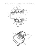
[0010] FIG. 2 shows a perspective view of the sound absorber of the compressor from FIG. 1,
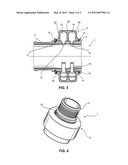
[0011] FIG. 3 shows an illustration, corresponding to FIG. 1, of a second embodiment of the sound absorber of the compressor,
[0012] FIG. 4 shows an illustration, corresponding to FIG. 2, of the second embodiment of the sound absorber of the compressor, and
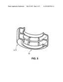
[0013] FIG. 5 shows a partially cut-away perspective view of a half-shell of the sound absorber of the compressor according to the invention.
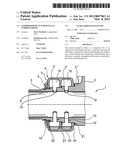
[0014] A first embodiment of a compressor 1 according to the invention will be described in detail below on the basis of a juxtaposition of FIG. 1 and FIG. 2. As can be seen from FIG. 1, the compressor 1, of which only an outlet connecting pipe 3 can be seen here, has an annular sound absorber 4 which is arranged, as a separate component, on the outer side of the outlet connecting pipe 3.
[0015] Two chambers 14, 15 which are divided by radial walls 22, 23 and 24 are formed in the interior of the sound absorber 4, which chambers 14, 15 are connected to the interior of the outlet connecting pipe 3 via two radial connecting ducts 12, 13 and two connecting ducts 12', 13' arranged opposite the connecting ducts 12, 13, and which chambers 14, 15 serve to generate sound absorption of the gas flow flowing out of the compressor housing (not illustrated).
[0016] A holding device 5 which is arranged on an end side 7, which points away from the compressor 1, of the sound absorber 4 has a multiplicity of clips, two of which clips are denoted, as representatives of all of the clips, by the reference numerals 8 and 9 in FIG. 2.
[0017] To fasten the sound absorber 4 to the outlet connecting pipe 3 of the compressor 1, after the walls 22, 23, 24 of the two chambers 14, 15 of the sound absorber 4 have been pushed against three shoulders 3', 3'', 3''' which are formed on the outer circumference of the outlet connecting pipe 3, the clips 8, 9 are clipped into an encircling holding groove 6 which is formed in the outlet connecting pipe 3. In each case one seal 19, 20 and 21 is arranged between the shoulders 3', 3'', 3''' of the outlet connecting pipe 3 and the walls 22, 23, 24, in order to seal off the sound absorber 4 with respect to the outside and to separate the two chambers 14 and 15.
[0018] FIG. 3 illustrates a further embodiment of a sound absorber 4' of the compressor 1 according to the invention. Here, identical components are denoted by the same reference symbols as in the first embodiment of FIG. 1. As can be seen from FIG. 3, the outlet connecting pipe 3 of the compressor 1 in this embodiment has, in contrast to the first embodiment, only one shoulder 3''' and no holding device 5 formed on the sound absorber 4', as in the first embodiment of FIG. 1. In this embodiment, to fasten the sound absorber 4' on the outlet connecting pipe 3 of the compressor 1, the sound absorber 4' is pushed against the shoulder 3''' of the outlet connecting pipe 3 and is fastened by means of a holding element 10 which is preferably designed as a circlip and engages into a holding groove 11 of the outlet connecting pipe 3. A seal 17 is arranged between the shoulder 3''' of the outlet connecting pipe 3 and the wall 24 of the sound absorber 4, and a seal 18 is arranged between the wall 22 and the circlip 10, in order to seal off the sound absorber 4' to the outside.
[0019] The above-described embodiments of the sound absorber 4 and 4' are constructed from two annular shell components or half shells 16, 16' which can be connected to one another, with the perspective, partially cut-away view of FIG. 5 illustrating only the half shell 16, which is preferably formed as a plastic injection-molded part, of the sound absorber 4, 4', and the chambers 14, 15 arranged therein. The two annular half shells 16, 16' may be differently-shaped components or, for adaptation to an available installation space of the compressor housing 2, may if necessary have a geometric shape differing from a circular cross section. To simplify assembly, the two half shells 16, 16' are connected to one another preferably by means of plastic welding, adhesive bonding or by means of clips. It is alternatively also conceivable for a complete sound absorber housing to have more than two components.
[0020] To complement the disclosure, reference is explicitly made to the diagrammatic illustration of the invention in FIGS. 1 to 5.
LIST OF REFERENCE SYMBOLS
[0021] 1 Compressor [0022] 2 Compressor housing [0023] 3 Outlet connecting pipe [0024] 3', 3'', 3''' Shoulder on outlet connecting pipe [0025] 4 Sound absorber [0026] 5 Holding device of the sound absorber [0027] 6 Holding groove in the outlet connecting pipe [0028] 7 End side pointing away from the compressor housing [0029] 8, 9 Clips [0030] 10 Holding element, circlip [0031] 11 Holding groove in the outlet connecting pipe [0032] 12, 13 Connecting duct [0033] 12', 13' Connecting duct [0034] 14, 15 Chambers [0035] 16, 16' Shell component, half shell [0036] 17, 18 Seals [0037] 19, 20, 21 Seals [0038] 22, 23, 24 Radial walls of the sound absorber
User Contributions:
Comment about this patent or add new information about this topic:
Images included with this patent application:
 |  |
 |  |
| Similar patent applications: | |
| Date | Title |
|---|---|
| 2009-03-05 | Compressor casing for an exhaust gas turbocharger |
| 2010-05-06 | Compressor for an exhaust gas turbocharger |
| 2011-09-15 | Device for sealing a bearing housing of an exhaust gas turbocharger |
| 2011-05-05 | Bearing housing body group of an exhaust-gas turbocharger |
| 2010-07-15 | Radial compressor with a diffuser for use in a turbocharger |
| New patent applications in this class: | |
| Date | Title |
|---|---|
| 2017-08-17 | Fan and air-conditioning apparatus using the same |
| 2016-12-29 | Turbine exhaust cylinder strut strip for shock induced oscillation control |
| 2016-07-14 | Suction device with sound mirror device |
| 2016-07-07 | Centrifugal fan, and fan equipped with sound-muffling box and using centrifugal fan |
| 2016-06-30 | Flexibly damped mounting assemblies for power gear box transmissions in geared aircraft engine architectures |
| New patent applications from these inventors: | |
| Date | Title |
|---|---|
| 2014-11-20 | Bearing housing of an exhaust-gas turbocharger |
| Top Inventors for class "Rotary kinetic fluid motors or pumps" | |
| Rank | Inventor's name |
|---|---|
| 1 | Gabriel L. Suciu |
| 2 | Frederick M. Schwarz |
| 3 | United Technologies Corporation |
| 4 | Brian D. Merry |
| 5 | Craig M. Beers |