Patent application title: DATA CENTER
Inventors:
Yao-Ting Chang (Tu-Cheng, TW)
Yao-Ting Chang (Tu-Cheng, TW)
Chao-Ke Wei (Tu-Cheng, TW)
Chao-Ke Wei (Tu-Cheng, TW)
Assignees:
HON HAI PRECISION INDUSTRY CO., LTD.
IPC8 Class: AA47F700FI
USPC Class:
211 26
Class name: Supports: racks special article electrically powered
Publication date: 2012-02-23
Patent application number: 20120043287
Abstract:
A data center includes a rack, and a server module installed in the rack.
The server module includes a top surface, a bottom surface, and left and
right surfaces. A number of closing members are positioned on the top
surface, the bottom surface, and the left and right surfaces of the
server module. The closing members resist against the rack to close the
interstices between the rack and the server module, to avoid hot air
vented from the server module flowing back through the interstice.Claims:
1. A data center comprising: a rack; a server module installed in the
rack, the server module comprising a top surface, a bottom surface, and
left and right side surfaces; and a plurality of closing members
positioned on the top surface, the bottom surface, and the left and right
surfaces of the server module; wherein each of the plurality of closing
members resists against an inner surface of the rack to close an
interstice between each of the top surface, bottom surface, left and
right surfaces of the server module and the rack, to avoid hot air vented
from the server module flowing back through the interstice.
2. The data center of claim 1, wherein the plurality of closing members comprising two bar-shaped first closing members respectively positioned on the top and bottom surfaces of the server module and adjacent to the front side of the server module, and two bar-shaped second closing members respectively positioned on the left and right surfaces of the server module and adjacent to the front side of the server module.
3. The data center of claim 2, wherein the first closing members and the second closing members cooperate to form a closing rectangle to resist against the rack to close the interstices between the rack and the server module.
4. The data center of claim 2, wherein a rear side of each of the first and second closing members is wedge-shaped, to reduce grip assistance between each of the first closing members and the second closing members, and the rack for easily sliding the server module in the rack.
5. The data center of claim 1, wherein each of the plurality of closing members is made of heat insulation material.
6. The data center of claim 5, wherein an outside of each of the plurality of closing member is made of plastic film.
7. The data center of claim 6, wherein an inside of each of the plurality of closing member is full of foam.
Description:
BACKGROUND
[0001] 1. Technical Field
[0002] The present disclosure relates to a data center.
[0003] 2. Description of Related Art
[0004] A data center usually includes a number of server modules arranged on a rack of the data center. The airflow for heat dissipating is generally from front to back in the server modules. However, the interstices between two adjacent server modules and between the server modules and the rack may let hot air vented out at the back flows back into the front side of the server modules.
BRIEF DESCRIPTION OF THE DRAWINGS
[0005] Many aspects of the present embodiments can be better understood with reference to the following drawings. The components in the drawings are not necessarily drawn to scale, the emphasis instead being placed upon clearly illustrating the principles of the present embodiments. Moreover, in the drawings, all the views are schematic, and like reference numerals designate corresponding parts throughout the several views.
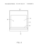
[0006] FIG. 1 is a schematic, front plan view of an exemplary embodiment of a data center including a server module, two first closing members, and two second closing members.
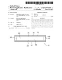
[0007] FIG. 2 is a schematic, top plan view of the data center of FIG. 1, with a top wall of the data center omitted.
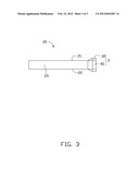
[0008] FIG. 3 is a schematic, side plan view of the server module, the two first closing members, and the two second closings member of FIG. 1.
DETAILED DESCRIPTION
[0009] The present disclosure, including the accompanying drawings, is illustrated by way of examples and not by way of limitation. It should be noted that references to "an" or "one" embodiment in this disclosure are not necessarily to the same embodiment, and such references mean at least one.
[0010] Referring to FIGS. 1 to 3, an exemplary embodiment of a data center includes a rack 10, a server module 20 received in the rack 10, and a number of closing members 3. The rack 10 includes a top wall 11, a bottom wall 12 substantially parallel to the top wall 10, left and right sidewalls 15 perpendicularly connected between the top wall 11 and the bottom wall 12, and front and back walls 16, 18 perpendicularly connected between the top wall 11 and the bottom wall 12.
[0011] The server module 20 includes a top surface 21, a bottom surface 22 substantially parallel to the top surface 21, a front surface 23, and left and right surfaces 25. The closing members 3 include two first closing members 30 and two second closing members 40. The first closing members 30 are positioned on the top surface 21 and the bottom surface 22, respectively. The second closing members 40 are positioned on the side surfaces 25, respectively. The first closing members 30 and the second closing members 40 are adjacent to the front side surface 23, and cooperate to form an enclosed rectangular area.
[0012] The first closing members 30 and the second closing members 40 are bar-shaped and made of heat isolative material. An outside of each of the first closing members 30 and the second closing members 40 is made of plastic film. An inside of each of the first closing members 30 and the second closing members 40 is full of foam. A rear end of each of the first closing members 30 and the second closing members 40 is wedge-shaped.
[0013] When the server module 20 is installed in the rack 10, the first closing members 30 resist against the top wall 11 and the bottom wall 12 respectively, and the second closing members 40 resist against the left and right sidewalls 15, so that the interstice between the top wall 11 of the rack 10 and the top surface 21 of the server module 20, the bottom wall 12 of the rack 10 and the bottom surface 22 of the server module 20, the left sidewall 15 of the rack 10 and the left surface 25 of the server module 20, the right sidewall 15 of the rack 10 and the right surface 25 of the server module 20 are filled with and enclosed by the first closing members 30 and the second closing members 40, which can avoid hot air vented from the server module 20 flowing back through the interstice.
[0014] In this embodiment, the wedge-shaped rear ends of the first closing members 30 and the second closing members 40 reduce surface contact area and therefore friction between each of the first closing members 30 and the second closing members 40, and the rack 10, for easily sliding the server module 20 in and out of the rack.
[0015] It is to be understood, however, that even though numerous characteristics and advantages of the embodiments have been set forth in the foregoing description, together with details of the structure and function of the embodiments, the present disclosure is illustrative only, and changes may be made in details, especially in matters of shape, size, and arrangement of parts within the principles of the embodiments to the full extent indicated by the broad general meaning of the terms in which the appended claims are expressed.
User Contributions:
Comment about this patent or add new information about this topic:
Images included with this patent application:
 |  |
 |  |
| New patent applications in this class: | |
| Date | Title |
|---|---|
| 2016-09-01 | Variable-depth multi device chassis |
| 2016-06-30 | Support member to position a system board |
| 2016-06-23 | Electronic device holder |
| 2016-06-02 | Removable fan tray |
| 2016-06-02 | Adjustable device carrier for modular chassis |
| New patent applications from these inventors: | |
| Date | Title |
|---|---|
| 2014-03-06 | Electronic device with heat dissipation assembly |
| 2014-02-20 | Rack-mount server system |
| 2014-01-02 | Container data center |
| 2013-10-03 | Fan |
| 2013-09-26 | Container with cooling system |
| Top Inventors for class "Supports: racks" | |
| Rank | Inventor's name |
|---|---|
| 1 | Stephen N. Hardy |
| 2 | Wen-Tsan Wang |
| 3 | Gregory M. Bird |
| 4 | Shane Obitts |
| 5 | Kaveh Didehvar |