Patent application title: Stop of a zipper
Inventors:
Tsai-Yu Chang (Pingzhen City, TW)
IPC8 Class: AA44B1936FI
USPC Class:
24436
Class name: Buckles, buttons, clasps, etc. zipper or required component thereof including means for obstructing movement of slider
Publication date: 2012-01-26
Patent application number: 20120017403
Abstract:
A stop of a zipper is mounted at an end of the zipper, is L-shaped and
has a mounting protrusion and a limiting protrusion formed transversely
on a proximal end of the mounting protrusion. When the mounting
protrusion of the stop is mounted into a slider, the limiting protrusion
and the slanted upper surface of the limiting protrusion prevent the
slider from further sliding into a channel of the slider so the slider
stops actually. Moreover, corners and edges of the stop may be all
rounded so the stop is able to smoothly slide into the slider.Claims:
1. A stop of a zipper being L-shaped and having a mounting protrusion
having a distal end and a proximal end; and a limiting protrusion formed
transversely on the proximal end of the mounting protrusion and being
wider than the mounting protrusion.
2. The stop of the zipper as claimed in claim 1, wherein the proximal end of the mounting protrusion is wider than the distal end of the mounting protrusion.
3. The stop of the zipper as claimed in claim 1, wherein the mounting protrusion has an outer side surface; the limiting protrusion has a lower side surface; and the stop further has a guiding surface smoothly formed concavely between the outer side surface of the mounting protrusion and the lower side surface of the limiting protrusion.
4. The stop of the zipper as claimed in claim 2, wherein the mounting protrusion has an outer side surface; the limiting protrusion has a lower side surface; and the stop has a guiding surface smoothly formed concavely between the outer side surface of the mounting protrusion and the lower side surface of the limiting protrusion.
5. The stop as claimed in claim 1, wherein the limiting protrusion has a distal end; a proximal end; and a slanted upper surface sloping up from the proximal end of the limiting protrusion to the distal end of the limiting protrusion.
6. The stop as claimed in claim 2, wherein the limiting protrusion has a distal end; a proximal end; and a slanted upper surface sloping up from the proximal end of the limiting protrusion to the distal end of the limiting protrusion.
7. The stop as claimed in claim 3, wherein the limiting protrusion has a distal end; a proximal end; and a slanted upper surface sloping up from the proximal end of the limiting protrusion to the distal end of the limiting protrusion.
8. The stop as claimed in claim 4, wherein the limiting protrusion has a distal end; a proximal end; and a slanted upper surface sloping up from the proximal end of the limiting protrusion to the distal end of the limiting protrusion.
9. The stop of the zipper as claimed in claim 5, wherein the mounting protrusion has a slanted upper surface sloping up from the distal end of the mounting protrusion to the proximal end of the mounting protrusion and is merged smoothly with the slanted upper surface of the limiting protrusion.
10. The stop of the zipper as claimed in claim 6, wherein the mounting protrusion has a slanted upper surface sloping up from the distal end of the mounting protrusion to the proximal end of the mounting protrusion and is merged smoothly with the slanted upper surface of the limiting protrusion.
11. The stop of the zipper as claimed in claim 7, wherein the mounting protrusion has a slanted upper surface sloping up from the distal end of the mounting protrusion to the proximal end of the mounting protrusion and is merged smoothly with the slanted upper surface of the limiting protrusion.
12. The stop of the zipper as claimed in claim 8, wherein the mounting protrusion has a slanted upper surface sloping up from the distal end of the mounting protrusion to the proximal end of the mounting protrusion and is merged smoothly with the slanted upper surface of the limiting protrusion.
13. The stop of the zipper as claimed in claim 9 has multiple corner being rounded and multiple edges being rounded.
14. The stop of the zipper as claimed in claim 10 has multiple corner being rounded and multiple edges being rounded.
15. The stop of the zipper as claimed in claim 11 has multiple corner being rounded and multiple edges being rounded.
16. The stop of the zipper as claimed in claim 12 has multiple corner being rounded and multiple edges being rounded.
Description:
BACKGROUND OF THE INVENTION
[0001] 1. Field of the Invention
[0002] The present invention relates to a stop of a zipper, especially to a stop that is disposed in pairs with another stop at an end of the zipper to prevent a slider from sliding out of the zipper.
[0003] 2. Description of the Prior Art(s)
[0004] Zippers are widely used on articles for daily use, such as clothes, bags and the like. A zipper has two tapes, a slider, two rows of teeth disposed respectively along the tapes and mounted through the slider, and four stops mounted on the tapes adjacent to ends of the rows of the teeth. When the slider is pulled to slide along the rows of the teeth, one row of the teeth alternatively engages or disengages from the other row of the teeth. Until the stops abut the slider, sliding of the slider is stopped.
[0005] However, since a conventional stop of the zipper is substantially rectangular, when the slider is pulled forcibly, the conventional stops slide into and are jammed in the slider, and the slider does not stop at an expected position. Moreover, as the slider is usually made of metal and the conventional stop is made of plastic, the conventional stop wears down easily causing jammed in the slider more easily.
[0006] Furthermore, since the conventional stop is formed on the tapes by an ultrasonic welding process, a connection between the conventional stop and the tape is insecure and the conventional stop drops from the tape easily.
[0007] To overcome the shortcomings, the present invention provides a stop of a zipper to mitigate or obviate the aforementioned problems.
SUMMARY OF THE INVENTION
[0008] The main objective of the present invention is to provide a stop of a slider. The stop is mounted at an end of the zipper, is L-shaped and has a mounting protrusion and a limiting protrusion formed transversely on a proximal end of the mounting protrusion.
[0009] The stop may be attached to and integrated with an end of a corresponding row of teeth of the zipper so the stop has improved durability and structural strength.
[0010] When the mounting protrusion of the stop is mounted into a slider, the limiting protrusion and the slanted upper surface of the limiting protrusion prevent the slider from further sliding into a channel of the slider so the slider stops actually. Moreover, corners and edges of the stop may be all rounded so the stop is able to smoothly slide into the slider.
[0011] Other objectives, advantages and novel features of the invention will become more apparent from the following detailed description when taken in conjunction with the accompanying drawings.
BRIEF DESCRIPTION OF THE DRAWINGS
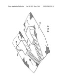
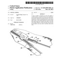
[0012] FIG. 1 is an operational perspective view of a stop of a zipper in accordance with the present invention;
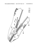
[0013] FIG. 2 is an enlarged operational perspective view of the stop of the zipper in FIG. 1;
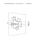
[0014] FIG. 3 is an enlarged operational top view of the stop of the zipper in FIG. 1; and
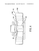
[0015] FIG. 4 is an operational front view of the stop of the zipper in FIG. 1.
DETAILED DESCRIPTION OF THE PREFERRED EMBODIMENTS
[0016] With reference to FIGS. 1 and 3, a zipper has two tapes 40, a slider 20 and two rows of teeth 30. The tapes 40 are sewn respectively on two corresponding edges of a cloth. The slider 20 has two channels 25, two sidewalls 24 and a dividing wall 23. The channels 25 are defined longitudinally through the slider 20. The sidewalls 24 are formed respectively on two opposite sides adjacent to a rear end of the slider 20. The dividing wall 23 is formed longitudinally at a front end of slider 20. The rows of the teeth 30 are arranged respectively along the tapes 40, are mounted respectively through the channel 25 of the slider 20 and alternatively engage each other when the slider 20 is pulled toward a close end of the zipper or disengage from each other when the slider 20 is pulled toward an open end of the zipper.
[0017] With further reference to FIGS. 2 and 4, the stop 10 in accordance with the present invention is mounted on one of the tapes 40, is attached to and is integrated with an end of a corresponding row of the teeth 30 so the stop 10 has improved durability and structural strength, is substantially L-shaped and has multiple corners, multiple edges, a mounting protrusion 101, a limiting protrusion 102, a guiding surface 103.
[0018] The corners and the edges of the stop 10 are all rounded.
[0019] The mounting protrusion 101 is disposed longitudinally along an edge of the tape 40, is attach to and is integrated with the end of the corresponding row of the teeth 30 and has a distal end, a proximal end, a slanted upper surface 104 and an outer side surface. The proximal end of the mounting protrusion 101 is wider than the distal end of the mounting protrusion 101. The slanted upper surface 104 of the mounting protrusion 101 slopes up from the distal end of the mounting protrusion 101 to the proximal end of the mounting protrusion 101.
[0020] The limiting protrusion 102 is formed transversely on the proximal end of the mounting protrusion 101, is wider than the mounting protrusion 101 and has a distal end, a proximal end, a slanted upper surface 105 and a lower side surface. The distal end of the limiting protrusion 102 has a thickness larger a height of the channel 25 of the slider 20. The slanted upper surface 105 of the limiting protrusion 102 slopes up from the proximal end of the limiting protrusion 102 to the distal end of the limiting protrusion 102 and preferably, is merged smoothly with the slanted upper surface 104 of the mounting protrusion 101.
[0021] The guiding surface 103 is smoothly formed concavely between the outer side surface of the mounting protrusion 101 and the lower side surface of the limiting protrusion 102.
[0022] The stop of the zipper as described has the following advantages. With reference to FIG. 3, when the slider 20 is pulled to a close end of the zipper, the mounting protrusion 101 of the stop 10 slides into a corresponding channel 25 of the slider 20. Since the limiting protrusion 102 is wider than the channel 25 of the slider 20, as a corresponding sidewall 24 of the slider 20 abuts the limiting protrusions 102 of the stop 10, the slider 20 stops sliding.
[0023] With further reference to FIG. 4, since the limiting protrusion 102 has the slanted upper surface 105 and the thickness of the distal end of the limiting protrusion 102 is larger than the height of the channel 25 of the slider 20, when the mounting protrusion 101 of the stop 10 is mounted into the slider 20, the limiting protrusion 102 does not further slides into the channel 25 of the slider 20 so the slider 20 stops actually. Moreover, since the corners and the edges of the stop 10 are all rounded, the stop 10 is able to smoothly slide into the slider 20.
[0024] Even though numerous characteristics and advantages of the present invention have been set forth in the foregoing description, together with details of the structure and features of the invention, the disclosure is illustrative only. Changes may be made in the details, especially in matters of shape, size, and arrangement of parts within the principles of the invention to the full extent indicated by the broad general meaning of the terms in which the appended claims are expressed.
User Contributions:
Comment about this patent or add new information about this topic:
| People who visited this patent also read: | |
| Patent application number | Title |
|---|---|
| 20140128595 | Process for the Preparation of -C-Aryl Glucosides |
| 20140128594 | Method for Manufacturing Hydroxyethyl Starch Derivatives |
| 20140128593 | SYNTHESIS OF 5-AZACYTIDINE |
| 20140128592 | METHODS AND MEANS FOR EFFICIENT SKIPPING OF EXON 45 IN DUCHENNE MUSCULAR DYSTROPHY PRE-mRNA |
| 20140128591 | ANTISENSE DESIGN |
Images included with this patent application:
 |  |
 |  |
 |
| Similar patent applications: | |
| Date | Title |
|---|---|
| 2010-10-28 | Safety device for a piece of luggage comprising a first outside zipper and a second inside zipper |
| 2010-11-25 | Plug pin, a position pin, and a plug pin set of a zipper |
| 2009-09-24 | Assembly for fixing a hose to a component of a domestic appliance |
| 2011-12-01 | Manufacturing method of a zipper with a horizontal bent potion and such zipper |
| 2012-02-02 | Mattress encasement for preventing bed bug escapement via a zipper opening |
| New patent applications in this class: | |
| Date | Title |
|---|---|
| 2014-06-12 | Top stop for slider |
| 2014-06-05 | Stop for a slide fastener, and a method for the manufacture thereof |
| 2014-03-06 | Strap formed slider end stops |
| 2014-01-23 | Slide fastener with separable bottom end stop |
| 2012-10-04 | Zipper with attached fastener |
| Top Inventors for class "Buckles, buttons, clasps, etc." | |
| Rank | Inventor's name |
|---|---|
| 1 | Keiichi Keyaki |
| 2 | Andreas Hörtnagl |
| 3 | Toshio Iwahara |
| 4 | Joachim Fiedler |
| 5 | Allison S. Conner |