Patent application title: SINGLE KNIFE CAPPING MACHINE
Inventors:
Xinhua Li (Hunan, CN)
Niansheng Yang (Hunan, CN)
Shen Liu (Hunan, CN)
Jianyong Liu (Hunan, CN)
Zhimin Duan (Hunan, CN)
Yue Tang (Hunan, CN)
IPC8 Class: AB65B728FI
USPC Class:
53329
Class name: Closing packages and filled receptacles separate closure applying closure securing means
Publication date: 2012-01-05
Patent application number: 20120000162
Abstract:
A capping machine, comprising a depressing member, a cap pressing device
connected to the depressing member, a supporting device, a transmission
device, a first driving wheel, a second driving wheel, and an actuating
wheel, wherein the first driving wheel is rotatably connected to the
depressing member, wherein the depressing member comprises a driver
member, while the cap pressing device comprises a driver ring, wherein
the driver member is received in the driver ring, wherein the depressing
member is engaged with the first driving wheel such that the first
driving wheel is arranged to drive the depressing member and the cap
pressing device in a vertical direction, wherein the depressing member is
driven to rotate by the transmission device, while the supporting device
is also rotatably connected to the transmission device so as to rotate
with the depressing member in a synchronized manner.Claims:
1. A capping machine, comprising a depressing member, a cap pressing
device connected to said depressing member, a supporting device, a
transmission device, a first driving wheel, a second driving wheel, and
an actuating wheel, wherein said first driving wheel is rotatably
connected to said depressing member, wherein said depressing member
comprises a driver member, while said cap pressing device comprises a
driver ring, wherein said driver member is received in said driver ring,
wherein said depressing member is engaged with said first driving wheel
such that said first driving wheel is arranged to drive said depressing
member and said cap pressing device in a vertical direction, wherein said
depressing member is driven to rotate by said transmission device, while
said supporting device is also rotatably connected to said transmission
device so as to rotate with said depressing member in a synchronized
manner.
2. The capping machine, as recited in claim 1, further comprising an auxiliary ring movably mounted on said cap pressing device, a gear assembly mounted on said cap pressing device at a position underneath said auxiliary ring, and a resilient element mounted between said auxiliary ring and said gear assembly for normally exerting an upward force to said cap pressing device.
Description:
BACKGROUND OF THE PRESENT INVENTION
[0001] 1. Field of Invention
[0002] The present invention relates to a capping device, and more particularly to a single knife capping device which is capable of making a wide variety of sealing caps, such as those used in pharmaceutical or food industry.
[0003] 2. Description of Related Arts
[0004] A conventional capping machine usually comprises a sealing device, a knife assembly, a supporting device, a transmission device, a dynamics wheel assembly, and a driving wheel. Before the capping machine is operated, a predetermined cap is placed on an opening of a bottle. The driving wheel is then arranged to move the bottle and the cap to a position underneath the sealing device and on top of the supporting device. When the capping machine operates, the supporting device moves the bottle and the cap toward the sealing device, which is arranged to rotatably engage with the cap so as to drive the cap to rotate with respect to the bottle. At the same time, the knife assembly is driven by the dynamics wheel assembly to move toward the sealing device for pressing against the cap and the bottle so as to tighten the engagement between the cap and the bottle. The knife assembly and the supporting device are then moved back to their original position for completing a pressing cycle. An advantage of this type of conventional capping machine is that it has simple structure. However, a major disadvantage is that the sealing performance is rather unstable, especially when a friction between the cap and the bottle is not sufficiently large enough. Moreover, when the supporting member moves the bottle upwardly toward the sealing device, the cap may fall off the bottle very easily.
SUMMARY OF THE PRESENT INVENTION
[0005] The invention is advantageous in that it provides a capping machine which is simple in structure, stable when operating and is capable of performing high quality capping procedures.
[0006] According to the present invention, the foregoing and other objects and advantages are attained by providing a capping machine, comprising a depressing member, a cap pressing device connected to the depressing member, a supporting device, a transmission device, a first driving wheel, a second driving wheel, and an actuating wheel, wherein the first driving wheel is rotatably connected to the depressing member, wherein the depressing member comprises a driver member, while the cap pressing device comprises a driver ring, wherein the driver member is received in the driver ring, wherein the depressing member is engaged with the first driving wheel such that the first driving wheel is arranged to drive the depressing member and the cap pressing device in a vertical direction, wherein the depressing member is driven to rotate by the transmission device, while the supporting device is also rotatably connected to the transmission device so as to rotate with the depressing member in a synchronized manner.
[0007] The capping machine further comprises an auxiliary ring movably mounted on the cap pressing device, a gear assembly mounted on the cap pressing device at a position underneath the auxiliary ring, and a resilient element mounted between the auxiliary ring and the gear assembly for normally exerting an upward force to the cap pressing device.
[0008] The present invention has the following advantages over conventional arts: [0009] 1. The capping machine of the present invention is simple in structure, stable in operation and is capable of producing high quality performance. The engagement between the bottle cover and the bottle is of very high quality and has very good aesthetic appearance. [0010] 2. In the present invention, the supporting device is also rotatably connected to the transmission device so as to rotate with the depressing member in a synchronized manner. This substantially resolves the problem of uneven capping of bottle which exists in conventional arts. Still further objects and advantages will become apparent from a consideration of the ensuing description and drawings.
BRIEF DESCRIPTION OF THE DRAWINGS
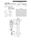
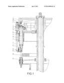
[0011] FIG. 1 is a schematic diagram of a capping machine according to a preferred embodiment of the present invention.
TABLE-US-00001 Explanation of numerals: 1. Depressing member 2. Cap pressing device 3. Supporting device 4. Transmission device 5. First driving wheel 6. Second driving wheel 7. Driver member 8. Driver ring 9. Auxiliary ring 10. Gear assembly 11. Resilient element 12. First driving arm 13. Second driving arm 14. Pressing knife 15. Depressing head 16. Actuating wheel
DETAILED DESCRIPTION OF THE PREFERRED EMBODIMENT
[0012] The preferred embodiment of the present invention is described below.
[0013] Referring to FIG. 1 of the drawings, a capping machine according to a preferred embodiment of the present invention is illustrated, in which the capping machine comprises a main frame, a depressing member 1, a cap pressing device 2 connected to the depressing member 1, a supporting device 3, a transmission device 4, a first driving wheel 5, a second driving wheel 6, and an actuating wheel 16. The first driving wheel 5 is mounted on the main frame, and is rotatably connected to the depressing member 1. The depressing member 1 comprises a driver member 7, while the cap pressing device 2 comprises a driver ring 8, wherein the driver member 7 is received in the driver ring 8. The depressing member 1 is engaged with the first driving wheel 5 such that the first driving wheel 5 is arranged to drive the depressing member 1 and the cap pressing device 2 in a vertical direction with respect to the main frame. Moreover, the depressing member 1 is driven to rotate by the transmission device 4. The capping machine further comprises a first driving arm 12 connecting between the cap pressing device 2 and the second driving wheel 6, a second driving arm 13 provided at a lower end portion of the cap pressing device 2, and a pressing knife 14 mounted to the second driving arm 13, wherein the cap pressing device 2 is driven to move by the second driving wheel 6 so as to drive the second driving arm 13 and the pressing knife 14 to move towards or away from the depressing member 1. On the other hand, the supporting device 3 is also rotatably connected to the transmission device 4 so as to rotate with the depressing member 1 in a synchronized manner.
[0014] There may exist a gap between the driver member 7 and the driver ring 8. The capping machine further comprises an auxiliary ring 9 movably mounted on the cap pressing device 2, a gear assembly 10 mounted on the cap pressing device 2 at a position underneath the auxiliary ring 9, a resilient element 11 mounted between the auxiliary ring 9 and the gear assembly 10 for normally exerting an upward force to the cap pressing device 2. Moreover, the resilient element 11 can also be used to minimize the gap between the driver member 7 and the driver ring 8. When the cap pressing device 2 is driven to move downwardly, the driver member 7 and the driver ring 8 ensure a relatively constant distance between the pressing knife and a depressing head 15 of the depressing member 1. This enables consistent pressing performance of the capping machine of the present invention.
[0015] The capping machine of the present invention operates as follows: the capping machine is for sealing a bottle by a predetermined bottle cap. The bottle and the bottle cap are arranged to be placed in between the depressing head 15 and the supporting device 3. The depressing member 1 is then driven to move downwardly along the main frame by the first driving wheel 5. As such the bottle and the bottle cap are sandwiched between the depressing member 1 and the supporting device 3. At the same time, the depressing member 1 and the supporting device 3 are driven to rotate in a synchronized manner. The depressing head 15 is arranged to bias against the bottle cap while the cap pressing device 2 is also driven to move downwardly as guided by the driver member 7 and the driver ring 8. At the same time, the pressing knife 14 is driven to move horizontally by the second driving wheel 6 to press against an engaging portion between the bottle cap and the bottle for sealing the bottle by the bottle cap. After the sealing of the bottle is accomplished, the pressing knife 14 is driven to move away from the bottle cap by the second driving wheel 6, while the depressing member 1 and the cap pressing device 2 are moved upwardly to release the pressing vertical pressing force against the bottle and the bottle cap. This completes one pressing cycle. From the above-mentioned operation, it can be appreciated that the bottle will be evenly sealed by the bottle cover. Moreover, since the depressing member 1 and the supporting device 3 are aligned with each other, the bottle cap will engage with the bottle in a smooth and tight manner. This provides a stable, desirable and reliable technical effect of the present invention.
[0016] One skilled in the art will understand that the embodiment of the present invention as shown in the drawings and described above is exemplary only and not intended to be limiting. It will thus be seen that the objects of the present invention have been fully and effectively accomplished. The embodiments have been shown and described for the purpose of illustrating the functional and structural principles of the present invention and is subject to change without departure from such principles. Therefore, this invention includes all modifications encompassed within the spirit and scope of the following claims.
User Contributions:
Comment about this patent or add new information about this topic:
| People who visited this patent also read: | |
| Patent application number | Title |
|---|---|
| 20120244420 | SECONDARY BATTERY |
| 20120244419 | ELECTROLYTE FOR A LITHIUM RECHARGEABLE BATTERY, LITHIUM RECHARGEABLE BATTERY INCLUDING THE SAME, AND METHOD OF MANUFACTURING A LITHIUM RECHARGEABLE BATTERY |
| 20120244418 | LIQUID-METAL NEGATIVE ELECTRODE FOR LITHIUM-ION BATTERIES |
| 20120244417 | LITHIUM ION SECONDARY BATTERY |
| 20120244416 | BEAM WELDING OF A MULTI-SHEET WORK STACK WITH A SINGLE COMMON WELDING INTERFACE |
Images included with this patent application:
 |  |
| New patent applications in this class: | |
| Date | Title |
|---|---|
| 2015-02-26 | Tool handling system |
| 2015-02-05 | Machine for applying threaded caps to containers |
| 2014-03-13 | Tray sealer |
| 2014-02-20 | Card sealing fixture and method of making same |
| 2013-03-28 | Carrier tape winding unit and apparatus of packing semiconductor package |
| Top Inventors for class "Package making" | |
| Rank | Inventor's name |
|---|---|
| 1 | Donald E. Weder |
| 2 | Dennis J. May |
| 3 | Samuel D. Griggs |
| 4 | Giuseppe Monti |
| 5 | Patrick R. Lancaster, Iii |