Patent application title: DIRECT SIDE POUR RISER SLEEVE
Inventors:
Carlos M. Leon (Brookfield, IL, US)
John Pirelli (Waukesha, IL, US)
Assignees:
International Engine Intellectual Property Company LLC
IPC8 Class: AB22D4150FI
USPC Class:
222591
Class name: Dispensing molten metal dispensing
Publication date: 2011-12-22
Patent application number: 20110309115
Abstract:
A direct side pour riser sleeve (10) for receiving molten metal from a
pouring basin (34) includes a generally cylindrical body (12) having an
exterior side surface (14) and an interior surface (24). Both of the
surfaces (14, 24) generally circumscribe a centerline axis (CL). The body
(12) has a top surface (16) configured to receive the pouring basin (34)
and a bottom surface (18) configured to be received in the drag portion
of the mold (48). The riser sleeve (10) also includes a pouring passage
(22) extending from the top surface (16) and that is defined by the
interior surface (24). The pouring passage (22) is configured to receive
the molten metal from the pouring basin (34). A taper portion (46) is
located on the exterior side surface (14) and has a decreasing diameter
towards the bottom surface (18).Claims:
1) A direct side pour riser sleeve for receiving molten metal from a
pouring basin, the riser sleeve being received in a drag portion of a
mold, the riser sleeve comprising: a generally cylindrical body having an
exterior side surface and an interior surface, both surfaces generally
circumscribing a centerline axis, the body having a top surface
configured to receive the pouring basin and a bottom surface configured
to be received in the drag portion of the mold; a pouring passage
extending from the top surface and defined by the interior surface, the
pouring passage configured to receive the molten metal from the pouring
basin; and a taper portion on the exterior side surface, the taper
portion having a decreasing diameter towards the bottom surface.
2) The riser sleeve of claim 1 wherein the pouring passage further comprises an upper chamber extending from the top surface, and a lower chamber in downstream fluid communication from the upper chamber.
3) The riser sleeve of claim 2 further comprising a filter disposed between the upper chamber and the lower chamber.
4) The riser sleeve of claim 3 further comprising at least one contact hole through the body from the exterior side surface to the interior surface, the contact hole being in fluid communication with the lower chamber.
5) The riser sleeve of claim 1 further comprising at least one contact hole through the body from the exterior side surface to the interior surface, the contact hole being in fluid communication with the pouring passage.
6) The riser sleeve of claim 5 wherein the at least one contact hole extends from the bottom surface along the exterior side surface.
7) The riser sleeve of claim 1 further comprising a filter disposed in the pouring passage generally centrally along the length of the body.
8) A direct side pour riser sleeve for receiving molten metal from a pouring basin, the riser sleeve providing fluid communication for molten metal to a casting cavity, the riser sleeve comprising: a generally cylindrical body having an exterior side surface and an interior surface, both surfaces generally circumscribing a centerline axis, the body having a top surface configured to receive the pouring basin and a bottom surface opposite of the top surface; a pouring passage extending from the top surface and defined by the interior surface, the pouring passage configured to receive the molten metal from the pouring basin; and at least one contact hole through the body from the exterior side surface to the interior surface, the contact hole being in fluid communication with the pouring passage and the casting cavity, wherein the molten metal flows in a direction generally transverse to the centerline axis at the contact hole.
9) The riser sleeve of claim 8 further comprising a taper portion on the exterior side surface, the taper portion having a decreasing diameter towards the bottom surface.
10) The riser sleeve of claim 8 wherein the pouring passage further comprises an upper chamber extending from the top surface, and a lower chamber in downstream fluid communication from the upper chamber.
11) The riser sleeve of claim 10 further comprising a filter disposed between the upper chamber and the lower chamber.
12) The riser sleeve of claim 10 wherein the at least one contact hole is in fluid communication with the lower chamber.
13) The riser sleeve of claim 8 wherein the at least one contact hole extends from the bottom surface along the exterior side surface.
14) The riser sleeve of claim 8 further comprising a filter disposed in the pouring passage generally centrally along the length of the body.
15) A direct side pour riser sleeve for receiving molten metal from a pouring basin, the riser sleeve providing fluid communication for molten metal to a casting cavity, the riser sleeve comprising: a body having a top surface configured to receive the pouring basin and a bottom surface opposite of the top surface, the body having an exterior side surface and an interior surface opposite the exterior side surface; an upper chamber extending from the top surface and defined by the interior surface, the upper chamber configured for receiving the molten metal from the pouring basin; a filter in downstream fluid communication with the upper chamber; and a lower chamber in downstream fluid communication with the filter and defined by the interior surface.
16) The riser sleeve of claim 15 further comprising a taper portion on the exterior side surface, the taper portion having a decreasing diameter towards the bottom surface.
17) The riser sleeve of claim 15 further comprising at least one contact hole through the body from the exterior side surface to the interior surface, the contact hole being in fluid communication with the lower chamber.
18) The riser sleeve of claim 15 wherein the at least one contact hole extends from the bottom surface along the exterior side surface.
19) The riser sleeve of claim 15 further comprising a connecting portion of the pouring passage disposed between the filter and the lower chamber.
20) The riser sleeve of claim 15 wherein the filter is disposed in the pouring passage generally centrally along the length of the body.
Description:
BACKGROUND
[0001] Embodiments described herein relate to a direct side pour riser sleeve for casting metal.
[0002] Molten metal is cast in molds to form various industrial and engineered castings for many applications, such as engine heads and engine blocks, as well as other components. Metal castings are often formed of iron, aluminum and other metals and alloys. To manufacture the components, the metal is melted and transferred to a holding furnace. From the holding furnace, the molten metal is transferred to a pouring basin.
[0003] In a conventional casting system, the pouring basin typically funnels the metal through a gating system that is designed to avoid turbulence and splashing as the molten metal enters the mold cavity. Turbulence and splashing of the molten metal can cause porosity in the cast part, and impurities and oxides may be entrained in the molten metal as it flows through the gating system. Conventional gating systems need multiple components, including sprues, runners and ingates that are used to cast the metal.
[0004] A conventional direct pour casting system reduces the components for casting metal as compared to a gating system. In a conventional direct pour casting system, the pouring basin funnels the metal to a riser sleeve that supplies the molten metal to the cavity in the casting mold. The riser sleeve supports a ceramic foam filter at a top surface of the riser sleeve where the pouring basin introduces the molten metal. The molten metal flows through the filter in a smooth, substantially laminar flow into the mold cavity. The filter also traps non-metallic inclusions in the liquid metal. The molten metal exits the riser sleeve at a bottom surface of the riser sleeve.
[0005] Direct pouring of castings simplifies the pattern design, enhances directional solidification, reduces cleaning room costs and maximizes casting yields. However, the riser sleeve may be difficult to secure in the mold during the pouring process, particularly on horizontally parted molding. Additionally, riser sleeves can only be used to cast one casting at a time. To use the conventional riser sleeve to pour more than one casting at a time, additional components, such as a nominal base and riser neck connections, are used in conjunction with the riser sleeve for the multiple casting sections to be fed.
SUMMARY
[0006] A direct side pour riser sleeve for receiving molten metal from a pouring basin includes a generally cylindrical body having an exterior side surface and an interior surface. Both of the surfaces generally circumscribe a centerline axis. The body has a top surface configured to receive the pouring basin and a bottom surface configured to be received in the drag portion of the mold. The riser sleeve also includes a pouring passage extending from the top surface and that is defined by the interior surface. The pouring passage is configured to receive the molten metal from the pouring basin. A taper portion is located on the exterior side surface and has a decreasing diameter towards the bottom surface.
[0007] Another direct side pour riser sleeve for receiving molten metal from a pouring basin includes a generally cylindrical body having an exterior side surface and an interior surface, where both surfaces generally circumscribe a centerline axis. The body has a top surface configured to receive the pouring basin and a bottom surface opposite of the top surface. A pouring passage extends from the top surface and is defined by the interior surface. The pouring passage is configured to receive the molten metal from the pouring basin. At least one contact hole is located through the body from the exterior side surface to the interior surface. The contact hole is in fluid communication with the pouring passage and the casting cavity. The molten metal flows in a direction generally transverse to the centerline axis at the contact hole.
[0008] In another direct side pour riser sleeve for receiving molten metal from a pouring basin, the riser sleeve includes a body having a top surface configured to receive the pouring basin, and a bottom surface opposite of the top surface. The body has an exterior side surface and an interior surface opposite the exterior side surface. An upper chamber extends from the top surface and is defined by the interior surface. The upper chamber is configured for receiving the molten metal from the pouring basin. A filter is in downstream fluid communication with the upper chamber, and a lower chamber is in downstream fluid communication with the filter. The lower chamber is also defined by the interior surface.
BRIEF DESCRIPTION OF THE DRAWINGS
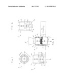
[0009] FIG. 1 is a front view and a top view of the direct side pour riser sleeve.
[0010] FIG. 2 is an elevation view of the direct side pour riser sleeve from the direction indicated by A-A in FIG. 1.
[0011] FIG. 3 is a schematic of the direct side pour riser sleeve, a pouring basin and a casting.
DETAILED DESCRIPTION
[0012] Referring to FIGS. 1-3, a direct side pour riser sleeve (herein "riser sleeve") is indicated generally at 10 and includes a generally cylindrical insulated body 12 having an exterior side surface 14, a top surface 16 and a bottom surface 18. The top surface 16 is generally annular and defines an inlet 20. The top surface 16 may have an outer diameter of about 4.88-inches, however other diameters are possible. The inlet 20 is in fluid communication with a pouring passage 22 defined by an interior surface 24. Both the exterior side surface 14 and the interior surface 24 generally circumscribe a centerline axis CL.
[0013] The pouring passage 22 includes an upper chamber 26 and a lower chamber 28. The upper chamber may have a height of about 3-inches and a diameter of about 4-inches at the top surface 16, however other dimensions are possible. Further, the upper chamber 26 may have a decreasing diameter from the top surface 18. The lower chamber 28 may have a height of about 2.75-inches and a diameter of about 4-inches at the bottom surface 18, however other dimensions are possible.
[0014] Between the upper chamber 26 and the lower chamber 28 is a connecting portion 30 of the pouring passage 22. A filter 32 is seated in the pouring passage 22 between the upper chamber 26 and the lower chamber 28. The filter 32 may have a thickness of about 0.75-inches, however other thicknesses are possible. Between the filter 32 and the lower chamber 28, the connecting portion 30 may have a length of about 0.5-inches, however other lengths are possible.
[0015] A pouring basin 34 is selectively attachable to the top surface 16 of the riser sleeve 10 to permit the fluid communication of molten metal from the pouring basin to the upper chamber 26. From the upper chamber 26, the molten metal flows through the filter 32. The filter 32 may be a ceramic foam filter, or any other filter suitable for filtering non-metallic inclusions and for regulating generally laminar flow of the molten metal.
[0016] From the filter 32, the molten metal flows through a connecting portion 30 to the lower chamber 28. At least one contact hole 36 is located through the body 12 generally transversely to the centerline axis CL, and extends from the exterior side surface 14 to the interior surface 24 at the lower chamber 28. The contact hole 36 may extend from the bottom surface 18 to a top surface 38 of the lower chamber 28, for example about 2.75-inches, however other lengths are possible. In the riser sleeve 10, two contact holes 36 are provided in the body 12, however any number of contact holes is possible. The multiple contact holes 36 may extend from the bottom surface 18, or alternatively may not extend from the bottom surface. The contact holes 36 may be disposed in equal or non-equal radial segments around the exterior side surface 14, and the contact holes 36 may have similar or non-similar shapes.
[0017] From the lower chamber 28, the molten metal flows out of the body 12 through the at least one contact hole 36 in a direction generally transverse to the centerline axis. The contact holes 36 allow for direct feeding to a casting cavity 40. Optionally, a sprue sleeve 42 may be used to feed the metal from the contact holes to the casting cavity 40.
[0018] The direct feeding of the molten metal through the contact holes 36 reduces the amount of metal needed for casting, and may eliminate the need for a sprue, runner and possibly one or more risers. Further, where multiple casting cavities 40 are used with multiple contact holes 36 in a single riser sleeve 10, there may be increased metal feeding per metal poured. Further still, using a single riser sleeve 10 to feed multiple casting cavities 40 allows space in the mold to be freed-up so that a mold may be used more efficiently.
[0019] The bottom surface 18 of the riser sleeve 10 is generally annular and defines a mold outlet 44. The exterior side surface 14 includes a lower taper portion 46, where the exterior surface of the body 12 has a decreasing diameter vertically towards the bottom surface 18. The diameter of the bottom surface 18 at the taper portion 46 may be about 5.12-inches, however other dimensions are possible. The taper portion 46 and the bottom surface 18 are configured to be set into and to sealingly engage a drag portion of the mold 48, where the drag portion also has a taper. The taper portion 46 secures the riser sleeve 10 in place as the riser sleeve moves along the assembly line in an automated horizontal molding machine, or any other molding machine. The taper portion 46 may have a length of about 1-inch, and the remainder of the exterior side surface 14 may have a length of about 6-inches, however other lengths are possible.
[0020] The filter 32 is located generally centrally along the length of the body 12, or about 3-inches from the top surface 16 and about 3.25-inches from the bottom surface 18, although other distances are possible. With the filter 32 disposed in the pouring passage 22 between the upper chamber 26 and the lower chamber 28, the center of gravity of the riser sleeve 10 is lower than a conventional riser sleeve, where the filter is typically located at the top surface 16 of the riser sleeve. With the filter 32 located closer to the bottom surface 18 and closer to the casting cavity 40, the pressure may be reduced as the metal enters the casting cavity, and there may be a reduction in slag or dross regeneration.
[0021] The riser sleeve 10 may provide efficiencies in one or more simultaneous castings, may replace or be used in conjunction with components of a gating system, and sits more securely in the casting machine Additionally, the riser sleeve 10 may be accepted on existing patterns with little to no modification of the sleeve or the pattern.
User Contributions:
Comment about this patent or add new information about this topic:
Images included with this patent application:
 |  |
| New patent applications in this class: | |
| Date | Title |
|---|---|
| 2016-02-04 | Ladle bottom and ladle |
| 2015-12-10 | Submerged entry nozzle |
| 2015-12-03 | Submerged entry nozzle |
| 2015-11-19 | Molten metal transfer system and rotor |
| 2014-11-20 | Double entry channel ladle bottom |
| Top Inventors for class "Dispensing" | |
| Rank | Inventor's name |
|---|---|
| 1 | Nick E. Ciavarella |
| 2 | John J. Mcnulty |
| 3 | Robert L. Quinlan |
| 4 | Heiner Ophardt |
| 5 | Andrew Jones |