Patent application title: METHOD FOR MONITORING DEFORMATION OF WELL EQUIPMENT
Inventors:
Kari-Mikko Jääskeläinen (Katy, TX, US)
Kari-Mikko Jääskeläinen (Katy, TX, US)
IPC8 Class: AE21B4700FI
USPC Class:
16625001
Class name: Wells processes with indicating, testing, measuring or locating
Publication date: 2011-12-01
Patent application number: 20110290477
Abstract:
A method of monitoring deformation and other characteristics of a casing
or other tubular or cylindrical well equipment in a well traversing an
underground formation, comprises:--providing a carrier rod having at
least one recess extending along at least part of the length of the rod,
in which recess an optical fiber assembly for monitoring strain,
temperature and/or other physical parameters is arranged, which assembly
is along at least part of its length bonded within the recess;--lowering
the carrier rod and well equipment simultaneously into the well such that
the rod is arranged in an annular space between the well equipment and
the wellbore;--securing the rod at a plurality of locations distributed
along its length to the well equipment; and--connecting the optical fiber
assembly to an optical signal transmission and reception assembly for
monitoring the physical parameters of the well equipment.Claims:
1. A method of monitoring deformation, strain, temperature and/or other
physical characteristics of a casing, sandscreen, electrical heater
and/or other tubular or cylindrical well equipment in a well traversing
an underground formation, the method comprising: providing a carrier rod
having at least one recess extending along at least part of the length of
the rod, in which recess a optical fiber assembly for monitoring strain,
temperature and/or other physical parameters is arranged, which optical
fiber assembly is along at least part of its length bonded within the
recess; lowering the carrier rod and well equipment simultaneously into
the well such that the carrier rod is arranged in an annular space
between the outer surface of the well equipment and the inner surface of
the wellbore; securing the carrier rod at a plurality of locations
distributed along its length to the well equipment; connecting the
optical fiber assembly to an optical signal transmission and reception
assembly which is configured to transmit optical signals through the
optical fiber assembly and to monitor deformation, strain, temperature
and/or other physical parameters of the well equipment on the basis of
any relationship between these parameters and reflection and/or
modification of optical signals at different locations along the length
of the optical fiber assembly.
2. The method of claim 1, wherein the carrier rod comprises a material having similar thermal expansion, and mechanical properties as the casing, sandscreen, electrical heater and/or other well equipment.
3. The method of claim 1, wherein the carrier rod is made of the same material as the casing, sandscreen and/or other well equipment.
4. The method of claim 1 wherein the carrier rod is arranged on a coil and bent into a substantially straight position before it is lowered into the well.
5. The method of claim 1 wherein the carrier rod is attached along selected intervals of its length by straps, welding, brazing and/or a bonding agent to the casing, sandscreen and/or other well equipment before it is lowered into the well.
6. The method of claim 1 wherein the carrier rod is secured to a tubular piece of well equipment by filling at least part of an annular space between the outer surface of the well equipment and the inner surface of the wellbore with a cement or other hardening composition and/or by expanding the tubular piece of well equipment such that at least part of an outer surface thereof is pressed against the inner surface of the wellbore.
7. The method of claim 1 wherein a plurality of carrier rods with optical fiber assemblies embedded in longitudinal recess are arranged at regular circumferential intervals around the outer surface of a tubular or cylindrical piece of well equipment.
8. The method of claim 1 wherein the method is used to monitor deformation of tubular or cylindrical well equipment during crude hydrocarbon fluid production operations and/or during steam injection into or electrical heating of a hydrocarbon containing formation, and wherein the monitored deformation of the well equipment is taken into account to adapt, modify and/or control the hydrocarbon fluid production, steam injection and/or electrical heating operations.
Description:
BACKGROUND OF THE INVENTION
[0001] The invention relates to a method for monitoring deformation of well equipment.
[0002] The current approach to monitor deformation of a well casing or other well equipment is to attach or glue fiber optical or other sensing cables directly to the well casing or other well equipment. Such installation of the sensing cable is cumbersome and time consuming with a significant risk of breaking the cable during attachment or during deployment in the well.
[0003] It is an object of the present invention to provide a method for monitoring deformation of a casing or other well equipment using a optical fiber assembly which can be attached quickly to the well casing and such that the optical fiber assembly is adequately protected against breaking during attachment or during deployment in the well.
SUMMARY OF THE INVENTION
[0004] In accordance with the invention there is provided a method of monitoring deformation, strain, temperature and/or other physical characteristics of a casing, sandscreen, electrical heater and/or other tubular or cylindrical well equipment in a well traversing an underground formation, the method comprising: [0005] providing a carrier rod having at least one recess extending along at least part of the length of the rod, in which recess a optical fiber assembly for monitoring strain, temperature and/or other physical parameters is arranged, which optical fiber assembly is along at least part of its length bonded within the recess; [0006] lowering the carrier rod and well equipment simultaneously into the well such that the carrier rod is arranged in an annular space between the outer surface of the well equipment and the inner surface of the wellbore; [0007] securing the carrier rod at a plurality of locations distributed along its length to the well equipment; [0008] connecting the optical fiber assembly to an optical signal transmission and reception assembly which is configured to transmit optical signals through the optical fiber assembly and to monitor deformation, strain, temperature and/or other physical parameters of the well equipment on the basis of any relationship between these parameters and reflection and/or modification of optical signals at different locations along the length of the optical fiber assembly.
[0009] It is preferred that the carrier rod comprises a material having similar thermal expansion, and mechanical properties as the casing, sandscreen, electrical heater and/or other well equipment.
[0010] The carrier rod may be arranged on a coil and bent into a substantially straight position before it is lowered into the well and may be attached along selected intervals of its length by straps, welding, brazing and/or a bonding agent to the casing, sandscreen and/or other well equipment before it is lowered into the well.
[0011] Alternatively, the carrier rod may be secured to a tubular piece of well equipment by filling at least part of an annular space between the outer surface of the well equipment and the inner surface of the wellbore with a cement or other hardening composition and/or by expanding the tubular piece of well equipment such that at least part of an outer surface thereof is pressed against the inner surface of the wellbore.
[0012] Optionally, a plurality of carrier rods with optical fiber assemblies embedded in longitudinal recess are arranged at regular circumferential intervals around the outer surface of a tubular or cylindrical piece of well equipment.
[0013] The method according to the invention may be used to monitor deformation of tubular or cylindrical well equipment during crude hydrocarbon fluid production operations and/or during steam injection into or electrical heating of a hydrocarbon containing formation, and wherein the monitored deformation of the well equipment is taken into account to adapt, modify and/or control the hydrocarbon fluid production, steam injection and/or electrical heating operations.
[0014] These and other features, embodiments and advantages of the method and according to the invention are described in the accompanying claims, abstract and the following detailed description of preferred embodiments disclosed in the accompanying drawings in which reference numerals are used which refer to corresponding reference numerals that are shown in the drawings.
BRIEF DESCRIPTION OF THE DRAWINGS
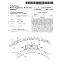
[0015] FIG. 1 shows a longitudinal sectional view of bend well casing within a curved wellbore;
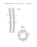
[0016] FIG. 2 shows, at a larger scale than in FIG. 1 a cross-sectional view of the bend well casing of FIG. 1 around which four rods with recesses in which strain monitoring optical fiber assemblies are arranged;
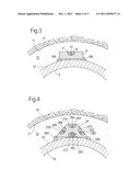
[0017] FIG. 3 shows a cross sectional view of a section of a well casing to which a rod with a recess, in which a strain monitoring assembly is arranged, is secured by spot welding;
[0018] FIG. 4 shows a cross sectional view of a section of a well casing to which a rod with a plurality of recesses, in which a strain monitoring assemblies are arranged, is secured by spot welding;
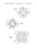
[0019] FIG. 5 shows an alternative embodiment of the rod, wherein the rod has a square cross-sectional shape;
[0020] FIG. 6 shows another alternative embodiment of the rod, wherein the rod has a cylindrical cross-sectional shape; and
[0021] FIG. 7 shows yet another alternative embodiment of the rod, wherein the rod has a cylindrical cross-sectional shape;
DETAILED DESCRIPTION OF THE DEPICTED EMBODIMENTS
[0022] FIG. 1 shows a curved wellbore 1 in which a bend casing 2 is arranged. The casing 2 is secured within the wellbore 1 by cement 3, which fills the annular space between the outer surface of the casing 2 and the inner surface of the wellbore 1.
[0023] In order to monitor stress, deformation, temperature and other features a series of four rods 4A-4D are embedded in the cement 3 around the casing 2. As illustrated in FIG. 2 each rod has a recess in which an optical strain monitoring fiber 5A-5D is embedded. The rods 4A-4D are preferably made of the same metal as the casing 2.
[0024] FIG. 3 shows in more detail a cross sectional view of an alternative embodiment of a rod 14, wherein the rod has a rectangular shape and is arranged in a cement body 12 between the inner surface 11 of a wellbore in an underground earth formation 10 and the outer surface 13 of a casing 9. The rod 14 has a recess 16 in which an optical strain monitoring fiber 15 is embedded within a protective filler 17. The rod 14 is secured at selected intervals along its length to the outer surface 13 of the casing 9 by spot welds 18A-B.
[0025] FIG. 4 shows a cross sectional view of an another alternative embodiment of a rod 24, wherein the rod has a trapezoidal shape and is arranged in a cement body 22 between the inner surface 21 of a wellbore in an underground earth formation 20 and the outer surface 23 of a casing 19. The rod 24 has at each of its four sides a recess 26A-D in which an optical strain monitoring fiber 25A-D is embedded within a protective filler 27A-D. The rod 24 is secured at selected intervals along its length to the outer surface 23 of the casing 19 by spot welds 28A-B. The optical fiber 25C is configured to measure temperature.
[0026] FIG. 5 shows a cross sectional view of yet another embodiment of a rod 34, wherein the rod has a square cross-sectional shape an has at each of its four sides a recess 36A-D in which an optical strain monitoring fiber 35A-D is embedded with a protective filler 37A-D.
[0027] FIG. 6 shows a cross sectional view of yet another embodiment of a rod 44, wherein the rod has a cylindrical cross-sectional shape an has at each of its four sides a recess 46A-D in which an optical strain monitoring fiber 45A-D is embedded with a protective filler 47A-D.
[0028] The rod 44 is surrounded by two concentric layers of protective coatings 48,49.
[0029] FIG. 7 shows a cross sectional view of yet another embodiment of a rod 54, wherein the rod has a cylindrical cross-sectional shape an has at each of its four sides a recess 56A-D in which an optical strain monitoring fiber 55A-D is embedded with a protective filler 57A-D.
User Contributions:
Comment about this patent or add new information about this topic:
Images included with this patent application:
 |  |
 |  |
| New patent applications in this class: | |
| Date | Title |
|---|---|
| 2022-05-05 | Method and system for subsurface to subsurface water injection |
| 2019-05-16 | Method of detecting methane in the bore of a blowout preventer stack |
| 2019-05-16 | Remotely operated inflow control valve |
| 2019-05-16 | Real time well integrity |
| 2019-05-16 | System and methodology for estimation of oil formation volume factor |
| Top Inventors for class "Wells" | |
| Rank | Inventor's name |
|---|---|
| 1 | Michael L. Fripp |
| 2 | Jean Marc Lopez |
| 3 | Michael H. Johnson |
| 4 | Jørgen Hallundbaek |
| 5 | Dennis P. Nguyen |