Patent application title: TEMPERATURE DISTRIBUTION IMPROVEMENT IN REFRIGERATED CONTAINER
Inventors:
Yu H. Chen (Manlius, NY, US)
Yu H. Chen (Manlius, NY, US)
Paul Chen (Manlius, NY, US)
Assignees:
CARRIER CORPORATION
IPC8 Class: AF25D1706FI
USPC Class:
62 89
Class name: Refrigeration processes circulating external gas
Publication date: 2011-11-24
Patent application number: 20110283719
Abstract:
The fan of a refrigeration machine operatively connected to a container
box is operated in one direction during normal operation and is
periodically operated in the opposite direction in order to reverse the
direction of airflow to and from the container box so as to thereby
promote a more uniform temperature distribution within the container box.
A door is automatically closed when operating in the reverse direction so
as to accelerate the airflow speed into the container box.Claims:
1. A method of operating a refrigerated container of the type having a
refrigeration machine at one end of the container with the refrigeration
machine having a fan for circulating warmer return air through an
evaporator coil to be cooled and then to flow rearwardly to the container
to cool its cargo, comprising the steps of: during normal operation,
operating the fan in one direction so as to draw in return air at one end
of the refrigeration machine and discharge it from the other end thereof;
and periodically reversing the direction of the fan so as to draw in
return air at the other end of the refrigeration machine and discharge it
from the one end thereof; whereby the air in the refrigerated container
is mixed so as to provide a more uniform temperature distribution
throughout.
2. A method as set forth in claim 1 wherein said fan operates in a blow-through mode during normal operation and as a draw-through mode during periodic reverse operation.
3. A method as set forth in claim 1 wherein said refrigeration machine one end is near the top thereof and the other end is near a bottom end thereof.
4. A method as set forth in claim 1 and including the steps of providing a door near said one end and opening said door when said fan is operating in said one direction and closing it when operating in said reverse direction.
5. A refrigeration machine for use with a container of a type for holding cargo to be refrigerated, comprising: an evaporator coil; a fan for causing warm air to be drawn in from one portion of the container box, to pass through the evaporator coil to be cooled, and then flow outwardly from the refrigeration machine to another portion of the container box; and a control for selectively operating the fan in one direction so as to draw in air from said container box one portion and return cooled air to said container box other portion and, periodically, reversing the direction of the fan such that the air is drawn in from said container box other portion and the cooled air is returned to said container box one portion.
6. A refrigeration machine as set forth in claim 5 and including a door near said box one portion and so as to be automatically opened when said fan is operated in said one direction and closed when said fan is operating in said reverse direction.
Description:
CROSS REFERENCE TO RELATED APPLICATION
[0001] This application claims priority to U.S. Provisional Patent Application Ser. No. 61/151,016 entitled "Temperature Distribution Improvement in Refrigerated Container," filed on Feb. 9, 2009. The content of this application is incorporated herein by reference in its entirety.
TECHNICAL FIELD
[0002] This invention relates generally to refrigerated containers and, more particularly, to a method and apparatus for obtaining a more uniform temperature distribution therein.
BACKGROUND OF THE INVENTION
[0003] Refrigerated containers are used to transport perishable cargo that requires very tight temperature control. The industry standard today is to have the refrigeration machine mounted at one end of the container box. The air in the container box is drawn into the refrigeration machine by fans which then blow the warmer air through an evaporator coil, with the cooled air then passing back into the container box to cool the cargo. The common problem with this arrangement is that the cargo's temperature tends to be higher towards the back door of the container and away from the refrigeration machine. The main reason is due to poor airflow distribution from the front to the back of the container box, with airflow being reduced significantly toward the back door. As a result, the temperature of the cargo is generally higher as it extends toward the rear door. The problem is exacerbated by the fact that the typical perishable cargo gives off heat of its own.
DISCLOSURE OF THE INVENTION
[0004] Briefly, in accordance with one aspect of the invention, the direction of the fan rotation is periodically reversed to thereby cause the direction of the airflow from and to the refrigerated container to be reversed to thereby improve the temperature distribution in the container box.
[0005] By another aspect of the invention, a plenum is provided at the top of the container box and is closed during the reverse operation in order to increase the airflow speed.
BRIEF DESCRIPTION OF THE DRAWINGS
[0006] FIG. 1 is a perspective view of a refrigerated container with the present invention incorporated therein.
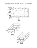
[0007] FIG. 2 is a schematic illustration thereof showing the airflow therein during normal operation.
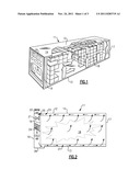
[0008] FIG. 3 is a graphic illustration of the temperature distribution therein during normal operation.
[0009] FIG. 4 is a schematic illustration of the airflow pattern which results in a refrigerated container when operated in accordance with the present invention.
[0010] FIGS. 5A and 5B are perspective views of a door portion thereof during normal and reverse flow operation thereof.
DETAILED DESCRIPTION OF THE INVENTION
[0011] A refrigerated container is shown generally at 11 as including a container box 12 having bottom and top sides 13 and 14 and front and rear ends 16 and 17. The container box 12 is designed to temporarily hold perishable cargo as shown at 18.
[0012] At the front end 16 of the container box 12, a refrigeration machine 19 is installed in such a manner as to fluidly communicate with the air in the container box 12 in order to cool that air for the purpose of refrigerating the cargo 18. The refrigeration machine 19 includes a standard refrigeration circuit comprising, in serial flow relationship, a compressor, a condenser, an expansion device and an evaporator. It is by the flow of the return air from the container box 12 and through the evaporator, that the air in the container box 12 is cooled. Circulation of air through the evaporator and into and out of the container box 12 as shown in FIG. 1 is caused by operation of a fan 21 within the refrigeration machine 19.
[0013] As will be seen in FIG. 2, the fan 21 is located near a top portion 22 of the refrigeration machine 19 which, during normal operation, acts to draw the return air forwardly along a top portion 23 of the container box 12 and through an open door 24. The warm air is then blown through the evaporator coil 24 where the air is cooled, with the cooled air then being discharged from a lower portion 26 of the refrigeration machine 19. From there, the cooled air flows rearwardly through a bottom portion 27 of the container box 12 as shown by the arrows. The cooler air rises upwardly through a t-bar floor as indicated by the upwardly extending arrows.
[0014] The cooled air passes upwardly through the cargo 18 with heat being transferred thereto from the cargo 18. The warmer air then continues upwardly to enter the top portion 23 of the container box 12 to complete the cycle.
[0015] It should be recognized that as the cooled air travels rearwardly, it gradually becomes warmer such that when it reaches the rear end 17 it is at its higher temperature. Further, since the flow of air through the container box 12 relies on the momentum created by the fan 21 and the convection currents within the container box 12, the velocity of flow will be reduced as its extends toward the rear wall 17. For that reason, a substantial temperature gradient will exist both in the vertical direction and in the horizontal direction, within the container box 12. Since the cargo is exposed to this distribution of air for long periods of time such as days or even weeks, the temperature of the cargo 18 within the container box reflects a similar temperature distribution. This cargo temperature distribution is shown in FIG. 3. Here it will be seen that the cooler cargo will be in the lower left portion of the container box and the warmer cargo will be at the upper right portion thereof. In fact, at the top and rear of the container box 12 there is a hot spot that may well impact the quality of the cargo. That is, the perishable cargo temperature distribution in a container determines the shelf life of the cargo. Thus, the shelf life of the cargo will be variable as indicated by the temperature distribution in FIG. 3. It is thus desirable to eliminate the hot spots and promote a more uniform temperature distribution within the container box 12. This is accomplished by operation of the system as shown in FIG. 4.
[0016] Here, the fan 21 is caused to operate in reverse so as to draw air through the evaporator coil 14 rather than blow air therethrough. This causes an associated reversal of airflow through the container box 12 as shown by the arrows. That is, the cooled air from the evaporator coil 24 passes upwardly through the fan 21 and into the top portion 22 of the refrigeration machine 19. From there it passes through the opening 30 and into the top portion 23 of the container box 12 to then flow rearwardly and downwardly as indicated by the arrows. The cooled air passes through the cargo 18 and then downwardly into the bottom portion 27 of the container box 12 before returning forwardly to the bottom portion 26 of the refrigeration machine 19 to complete the cycle. This reversal of flow causes mixing of the air within the container box 12 so as to thereby promote a more uniform distribution.
[0017] In order to increase the airflow speed, and thus the "throw", during reverse flow operation, the door 25 is provided at the front end of the container top portion 23 as shown in FIGS. 5A and 5B. That is, as shown in FIG. 5A, during normal operation the return airflow causes the door 25 to open and allow the air to flow freely across the entire cross section of the top portion 23 as shown. However, in reverse flow operation, the flow of air will cause the door 25 to be moved to the closed position such that the opening 30 is of reduced cross section as shown in FIG. 5B. This will, in turn, cause the velocity of the airflow therethrough to increase, which will provide better "throw" and further promote mixing.
[0018] It is recognized that the blow-through operation of the fan 21 as shown in FIG. 2 is more efficient then the draw-through approach as shown in FIG. 4. However, the time in which the fan 21 is operated in the reverse mode is relatively small compared with the time that it operates in the normal mode as shown in FIG. 2. A typical time cycle of normal and periodic reverse operation is shown in FIG. 6.
[0019] While the present invention has been particularly shown and described with reference to the preferred mode as illustrated in the drawing, it will be understood by one skilled in the art that various changes in detail may be effected therein without departing from the spirit and scope of the invention as defined by the claims.
User Contributions:
Comment about this patent or add new information about this topic:
Images included with this patent application:
 |  |
 |
| Similar patent applications: | |
| Date | Title |
|---|---|
| 2010-04-22 | Refrigerant distribution improvement in parallell flow heat exchanger manifolds |
| 2008-11-27 | Method for controlling temperature in multiple compartments for refrigerated transport |
| 2012-02-09 | Temperature controlled compartment and method for a refrigerator |
| 2009-01-08 | Low temperature air separation process for producing pressurized gaseous product |
| 2010-08-05 | Temperature conditioning device for a food transport container |
| New patent applications in this class: | |
| Date | Title |
|---|---|
| 2016-06-23 | Electronically commutated fan motors and systems |
| 2016-06-23 | Air conditioning system for tractor trailers |
| 2016-05-26 | Modular hvac system with engine-on and engine-off operation |
| 2016-04-14 | Method for the conditioning of air, and air-conditioning system |
| 2016-04-14 | Refrigerated container with dual air curtain |
| New patent applications from these inventors: | |
| Date | Title |
|---|---|
| 2021-01-14 | Engineless transport refrigeration unit |
| 2019-01-03 | Controlling a refrigeration unit in response to a specific cargo load |
| 2018-12-27 | Determining hot cargo load condition in a refrigerated container |
| 2018-12-27 | Methods and systems for checking proper airflow within a container |
| 2015-12-03 | Embedded cargo sensors for a refrigeration system |
| Top Inventors for class "Refrigeration" | |
| Rank | Inventor's name |
|---|---|
| 1 | Michael F. Taras |
| 2 | Alexander Lifson |
| 3 | Koji Yamashita |
| 4 | Hiroyuki Morimoto |
| 5 | Patrick J. Boarman |