Patent application title: LAUNDRY TREATING APPLIANCE SUSPENSION SYSTEM
Inventors:
Christoph J. Miller (Saint Joseph, MI, US)
Christoph J. Miller (Saint Joseph, MI, US)
John L. Patera (Saint Joseph, MI, US)
Assignees:
WHIRLPOOL CORPORATION
IPC8 Class: AD06F3500FI
USPC Class:
68 13 R
Class name: Textiles: fluid treating apparatus machines combined
Publication date: 2011-10-13
Patent application number: 20110247372
Abstract:
A suspension system for a laundry treating appliance having a cabinet and
a tub comprises a rod coupled to the cabinet and a shock absorber coupled
between the rod and the tub. A socket interface on the rod reduces side
loading forces on the shock absorber. The socket interface may be
separate from the shock absorber.Claims:
1. A laundry treating appliance, comprising: a cabinet defining an
interior; a tub located within the chassis and having at least one
socket; a suspension system coupling the tub to the chassis and
comprising at least one suspension strut assembly comprising: an
elongated rod defining a longitudinal axis and extending between the tub
and cabinet, with one end of the rod mounted to the cabinet and another
end of the rod passing through the socket, and the longitudinal axis
oriented at an angle relative to the vertical; a damper slidably mounted
on the rod; a spring having one end coupled to the rod and another end
coupled to the damper; a force director operably mounted to the rod and
having one end operably coupled to the socket and another end operably
coupled to the damper such that forces imparted by the tub onto the force
director along an axis unaligned with the longitudinal axis are aligned
with the longitudinal axis of the rod.
2. The laundry treating appliance of claim 1 wherein the force director comprises a first surface that abuts a second surface on the socket, with the first and second surfaces being complementary.
3. The laundry treating appliance of claim 2 wherein the first and second surfaces have the substantially the same radius of curvature.
4. The laundry treating appliance of claim 3 wherein the force director comprises a third surface, opposite the first surface, with the third surface contacting the damper.
5. The laundry treating appliance of claim 4 wherein the third surface is planar, and the unaligned forces acting on the first surface emanate through the third surface aligned with the longitudinal axis.
6. The laundry treating appliance of claim 5 wherein the force director has the shape of a truncated cone from the first surface to the third surface.
7. The laundry treating appliance of claim 5 wherein the damper comprises a cap having a fourth surface complementary to the planar surface.
8. The laundry treating appliance of claim 1 wherein the damper is slidably mounted to the rod.
9. The laundry treating appliance of claim 8 wherein the damper comprises a compressible dampening insert surrounding the rod.
10. The laundry treating appliance of claim 1 wherein the spring is a coil spring.
11. A suspension strut assembly for suspending a tub of a washing machine to a chassis of the washing machine, comprising: an elongated rod defining a longitudinal axis, with one end configured to mount to the chassis and an opposite end; a damper slidably mounted on the rod; a spring having one end coupled to the rod and another end coupled to the damper; a force director operably mounted to the rod and having one end configured to operably couple to the tub and another end operably coupled to the damper, and shaped such that forces imparted onto the force director opposite the damper and along an axis unaligned with the longitudinal axis are aligned with the longitudinal axis of the rod.
12. The suspension rod assembly of claim 11 wherein the force director comprises a first surface for confronting the tub and shaped to direct forces acting on the front surface axially along the longitudinal axis.
13. The suspension rod assembly of claim 12 wherein the force director comprises a second surface, opposite the first surface, with the second surface contacting the damper, and the unaligned forces acting on the first surface emanate through the second surface aligned with the longitudinal axis.
14. The suspension rod assembly of claim 13 wherein the first surface has a radius of curvature and the second surface is a planar surface.
15. The suspension rod assembly of claim 14 wherein the force director has the shape of a truncated cone from the first surface to the second surface.
16. The suspension rod assembly of claim 15 wherein the damper comprises a cap having a third surface complementary to the planar surface.
17. The suspension rod assembly of claim 16 wherein the damper is the damper slidably mounted to the rod.
18. The suspension rod assembly of claim 17 wherein the damper comprises a compressible friction member surrounding the rod.
19. The suspension rod assembly of claim 18 wherein the spring is a coil spring.
Description:
CROSS REFERENCE TO RELATED APPLICATIONS
[0001] The present application claims the benefit of U.S. Provisional Patent Application No. 61/323,451, filed Apr. 13, 2010, which is incorporated herein by reference in its entirety.
BACKGROUND OF THE INVENTION
[0002] Laundry treating appliances, such as a washing machine or a clothes dryer, may include an outer cabinet and a tub housed within the cabinet and coupled to the cabinet by a suspension system. Such suspension systems may include a plurality of suspension strut assemblies which hang the tub from the cabinet. Each suspension strut assembly may have dampening means for reducing the movement and vibration of the tub.
SUMMARY OF THE INVENTION
[0003] The invention relates to a suspension system for a laundry treating appliance having a cabinet and a tub. The suspension system includes a rod coupled to the cabinet, a shock absorber coupled between the rod and the tub, and a socket interface coupled to the rod which reduces side loading forces on the shock absorber.
BRIEF DESCRIPTION OF THE DRAWINGS
[0004] In the drawings:
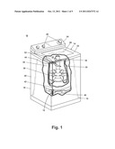
[0005] FIG. 1 is a perspective view of a laundry treating appliance, with a portion of the laundry treating appliance partially cut away to show interior components, including a suspension system according to one embodiment of the invention.
[0006] FIG. 2 is a partial sectional view of the laundry treating appliance from FIG. 1 and illustrating one suspension strut assembly of the suspension system.
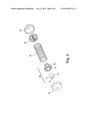
[0007] FIG. 3 is an exploded view of a portion of the suspension system of FIG. 1, including a spring and damper of the suspension strut assembly.
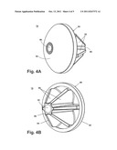
[0008] FIGS. 4A and 4B are top and bottom perspective views of a socket interface of the suspension system of FIG. 1.
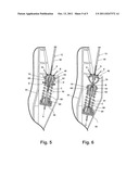
[0009] FIG. 5 is a partial sectional view of the laundry treating appliance from FIG. 1, illustrating forces acting on the suspension system without the socket interface.
[0010] FIG. 6 is a partial sectional view of the laundry treating appliance from FIG. 1, illustrating forces acting on the suspension system with the socket interface.
DESCRIPTION OF EMBODIMENTS OF THE INVENTION
[0011] The present invention relates to a suspension system for an appliance, such as a laundry treating appliance. In particular, one embodiment of the invention relates to a laundry treating appliance suspension system having an improved force management.
[0012] FIG. 1 illustrates one embodiment of a laundry treating appliance 10 having a suspension system 12 according to one embodiment of the invention. As illustrated, the laundry treating appliance 10 is a vertical-axis washing machine; however, the laundry treating appliance 10 may be any appliance which performs a cycle of operation on laundry, non-limiting examples of which include a horizontal-axis washing machine; a horizontal or vertical axis clothes dryer; a combination washing machine and clothes dryer; a tumbling or stationary refreshing/revitalizing machine; an extractor; a non-aqueous washing apparatus; and a revitalizing machine. As used herein, the term "vertical-axis" washing machine refers to a washing machine having a rotatable drum that rotates about a generally vertical axis relative to a surface that supports the washing machine. However, the rotational axis need not be perfectly vertical to the surface. The drum may rotate about an axis inclined relative to the vertical axis, with fifteen degrees of inclination being one example of the inclination. Similar to the vertical axis washing machine, the term "horizontal-axis" washing machine refers to a washing machine having a rotatable drum that rotates about a generally horizontal axis relative to a surface that supports the washing machine. The drum may rotate about the axis inclined relative to the horizontal axis, with fifteen degrees of inclination being one example of the inclination. The laundry treating appliance 10 described herein shares many features of a traditional automatic washing machine, which will not be described in detail except as necessary for a complete understanding of the invention. It is also understood that the suspension system 12 is applicable to appliances other than laundry treating appliances.
[0013] As illustrated in FIG. 1, the laundry treating appliance 10 may have a cabinet 14 defined by a front wall 16, a rear wall 18, and a pair of side walls 20 supporting a top wall 22. A user interface 24 on the cabinet 14 has multiple controls 26, which a user can select to operate the laundry treating appliance 10 through the steps of a wash cycle. A chassis or frame may be provided on which the various walls may be mounted.
[0014] The top wall 22 may have an openable door or lid 28 and may be selectively moveable between opened and closed positions to close an opening in the top wall 22, which provides access to the interior of the cabinet 14. A rotatable drum 30 may be disposed within the interior of the cabinet 14 and defines a treating chamber 32 for treating laundry. The drum 30 may be positioned within an imperforate tub 34. The drum 30 may include a plurality of perforations 36, such that liquid may flow between the tub 34 and the drum 30 through the perforations 36. A clothes mover 38 may be located in the drum 30 to impart mechanical agitation to a load of clothing articles placed in the drum 30. An electric motor 40 may be coupled to the clothes mover 38 and may be located beneath the tub 34.
[0015] At least the tub 34 is supported within the cabinet 14 by the suspension system 12. The suspension system 12 can comprise a plurality of suspension strut assemblies 42, only one of which is visible in FIG. 1, which hang the tub 34 from the cabinet 14. While the illustrated laundry treating appliance 10 includes both the tub 34 and the drum 30, with the drum 30 defining the laundry treating chamber 32, it is within the scope of the invention for the laundry treating appliance 10 to include only one receptacle, with the receptacle defining the laundry treating chamber for receiving the laundry load to be treated and supported by the suspension system 12.
[0016] FIG. 2 is a partial sectional view of the laundry treating appliance 10 from FIG. 1. Each suspension strut assembly 42 may be coupled to the cabinet 14 by one or more brackets 44, which can be positioned near the top corners of the cabinet 14, and to the tub 34 by one or more sockets 46, which can be integrally formed with or attached to a lower portion of the tub 34. Each suspension strut assembly 42 comprises a rod 50 having an upper support 52 at a first end of the rod 50 which is coupled to the bracket 44 and a shock absorber 54 at a second end of the rod 50, opposite the upper support 52, which is coupled to the socket 46. A stop 56 is also coupled to the rod 50 and functions to limit the upward movement of the tub 34 within the cabinet 14.
[0017] The shock absorber 54 may comprise a first end cap 58, a piston 60, a damper 62, a second end cap 64, and a spring 66. The end caps 58, 64, piston 60, and damper 62 may be mounted on the rod 50, with the first end cap 58 nearest the terminal end of the rod 50, the piston 60 adjacent the first end cap 58, the damper 62 spaced from both the first end cap 58 and the piston 60, and the second end cap 64 adjacent the damper 62. The spring 66 may be mounted around the piston 60 and is positioned between the first end cap 58 and the damper 62. The spring 66 allows compliance in the connection of the tub 34 to the cabinet 14, aiding to reduce vibration and allow the tub 34 to move freely within the cabinet 14. The damper 62 may provide friction force that is used to reduce the movement and vibration of the tub.
[0018] FIG. 3 is an exploded view of a portion of the suspension system 12 of FIG. 1. The damper 62 may include an outer housing 68 a dampening insert 70 received by a chamber 72 in the outer housing 68. The dampening insert 70, which is illustrated as a compressible friction member, may be a tube 74 of foam material having a passage 76 for receiving the rod 50. The inner diameter of the tube 74, i.e. the diameter of the passage 76, may be smaller than the outer diameter of the rod 50, causing the inner surface of the tube 74 to compress outwardly in order for the tube 74 to stretch over the rod 50. The outer diameter of the tube 74 may be greater than the diameter of the chamber 72, thereby compressing at least the outer surface of the tube 74 inwardly. As the damper 62 moves relative to the rod 50, the friction force of the foam tube 74 compressed on the rod resists the movement. Thus, the radial compression of the foam tube 74 in towards the rod 50 produces a damping force that hampers axial movement of the shock absorber 54 along the rod 50. The dual compressive forces created by the foam tube 74 also increase the friction force generated when the damper 62 is moved relative to the stationary rod 50, thereby generating heat.
[0019] The foam tube 74 may be injected with grease, which helps conduct frictional heat away from the rod 50 so that the damper 62 does not overheat. The grease also helps lubricate the interface between the tube 74 and the rod 50 to prevent the foam material from damage caused by repetitive movement relative to the rod 50. The grease can also help make the foam material more compliant and less stiff to further protect the tube 74 from damage. Alternatively, the dampening insert 70 may be made as a strip of foam wrapped around the rod 50 or simply compressed in some manner and designed to function similarly to the foam tube 74 described above.
[0020] As shown in FIG. 2, a force director illustrated in the form of a socket interface 78 may be positioned on the rod 50 between the socket 46 and the shock absorber 54, and functions to redirect force on the shock absorber 54 to a vector that is substantially coaxial with a longitudinal axis X of the rod 50. The socket interface 78 may be a separate component from the shock absorber 54.
[0021] FIGS. 4A and 4B are top and bottom perspective views of the socket interface 78. The socket interface 78 has a generally truncated cone-shaped body 80, with a base surface 82 and an angled side surface 84 extending from the base surface 82 to a top surface 86 having a smaller surface area than the base surface 82. The base surface 82 may be convexly curved. The side surface 84 may include one or more angled struts 88 extending from the top surface 86 to the base surface 82. A passage 90 for receiving the rod 50 extends through the body 80.
[0022] FIG. 5 is a partial sectional view of the laundry treating appliance 10 from FIG. 1, illustrating forces acting on the suspension system 12 without the socket interface 78. Ideal force, represented by vector A, transmitted to the shock absorber 54 would be coaxial with the axis X of the rod 50. However, in reality, due to the suspension interface with the tub 34, actual force, represented by vectors B is imparted onto the shock absorber 54 at an angle to the axis X. Because the actual force B is not parallel to the axis X, a portion of the force transmitted back by the shock absorber 54 will not be parallel to the axis X. One portion will be redirected in an axial direction, represented by vector C, while the other portion is redirected in the radial direction, represented by vector D. The force vector D acting perpendicular to the rod 50 adds a side loading to the damper 62, which may torque the damper 62 in the direction of vector D while it moves along the rod 50.
[0023] The torque applied to the damper 62 while it oscillates up and down relative to the rod 50 during a cycle of operation of the laundry treating appliance 10 can prematurely wear and damage the foam material of the dampening insert 70, which reduces the effectiveness of the damper 62 in producing friction force to reduce the movement and vibration of the tub 34. If the side loading is great enough, the suspension assembly 12 can fail within a single cycle of operation of the laundry treating appliance 10.
[0024] FIG. 6 is a partial sectional view of the laundry treating appliance 10 from FIG. 1, illustrating forces acting on the suspension system 12 with the socket interface 78. The socket interface 78 helps to manage any aspects of side loading to ensure the suspension assembly 12 does not fail and the laundry treating appliance 10 remains operable. Similarly to FIG. 5, actual force, represented by vectors E is imparted onto the socket interface 78 at an angle to the axis X. However, due to the shape of the socket interface 78, actual force, represented by vector B, imparted onto the shock absorber 54 is coaxial with the axis X, and is therefore, collinear with the ideal force vector A. Because the actual force B is parallel to the axis X, the force transmitted back by the shock absorber 54, represented by vector C, will be parallel to the axis X. Without any substantial radially-directed force transmitted back, there will be no substantial side loading on the damper 62.
[0025] The invention described herein provides a suspension system with improved force management. The socket interface 78 of the suspension system 12 redirects forces acting on the suspension system 12 to be parallel to the rod 50, which is ideal. This reduces or eliminates side loading on the damper 62, which increases the effectiveness of the damper 62 and reduces the possibility of suspension failure.
[0026] While the invention has been specifically described in connection with certain specific embodiments thereof, it is to be understood that this is by way of illustration and not of limitation. Reasonable variation and modification are possible within the scope of the forgoing disclosure and drawings without departing from the spirit of the invention which is defined in the appended claims.
User Contributions:
Comment about this patent or add new information about this topic:
Images included with this patent application:
 |  |
 |  |
 |
| Similar patent applications: | |
| Date | Title |
|---|---|
| 2012-02-16 | Laundry treating appliance having a dispensing drawer |
| 2010-11-11 | Auxiliary laundry treating machine and multiple treating system including the same |
| 2011-10-13 | Laundry treating appliance with force damping feet |
| 2011-10-13 | Laundry treating appliance with tub ring |
| 2009-12-03 | Water supply control for a steam generator of a fabric treatment appliance using a weight sensor |
| New patent applications in this class: | |
| Date | Title |
|---|---|
| 2016-07-07 | Fluid additive dispenser for a washing machine appliance |
| 2016-06-02 | Washing machine |
| 2016-04-14 | Washing machine appliance spray hose assembly |
| 2016-03-17 | Water valve for a washing machine and method of manufacturing the same |
| 2015-12-03 | Coin washing machine with charging function |
| New patent applications from these inventors: | |
| Date | Title |
|---|---|
| 2020-03-19 | Laundry treating appliance |
| 2017-06-01 | Laundry treating appliance |
| 2017-06-01 | Laundry treating appliance |
| 2015-11-19 | Method and apparatus for using gravity to precisely dose detergent in a washing machine |
| 2013-01-03 | Laundry treating appliance with method to reduce drum excursions |
| Top Inventors for class "Textiles: fluid treating apparatus" | |
| Rank | Inventor's name |
|---|---|
| 1 | Doo Young Ryu |
| 2 | Ig Geun Kwon |
| 3 | Sang Yeon Pyo |
| 4 | Dong Won Kim |
| 5 | Jae Ryong Park |