Patent application title: Needle Delivered Imaging Device
Inventors:
Stephen C. Jacobsen (Salt Lake City, UT, US)
Fraser M. Smith (Salt Lake City, UT, US)
IPC8 Class: AA61B104FI
USPC Class:
600109
Class name: Surgery endoscope with camera or solid state imager
Publication date: 2011-10-06
Patent application number: 20110245605
Abstract:
A hollow elongated cylinder is disclosed having a distal end and a
proximal end, the proximal end configured to be removably connectable to
a distal end of a syringe. An umbilical is removably inserted within said
cylinder and configured for detachable connection to a data processor and
a display device having a solid state imaging device disposed on a distal
end of the umbilical. A lens system is disposed on a distal end of the
solid state imaging device. The umbilical is inserted within the cylinder
such that the distal end of the lens system is disposed at approximately
the distal end of the cylinder.Claims:
1. A medical device, comprising: a hollow elongated cylinder having a
distal end and a proximal end, the proximal end configured to be
removably connectable to a distal end of a syringe; an umbilical
removably inserted within said cylinder and configured for detachable
connection to a data processor and a display device; a solid state
imaging chip disposed on a distal end of the umbilical; and a lens system
disposed on a distal end of the solid state imaging chip, wherein the
umbilical is inserted within the cylinder such that the distal end of the
lens system is disposed at approximately the distal end of the cylinder.
2. The medical device of claim 1, wherein the lens system is a GRIN lens.
3. The medical device of claim 1, wherein the hollow elongated cylinder further comprises a valve near a proximal end of the cylinder.
4. The medical device of claim 3, wherein the valve is a pressure-responsive slit valve.
5. The medical device of claim 1, wherein the hollow elongated cylinder is a non-coring needle.
6. The medical device of claim 1, wherein the hollow elongated cylinder is a coring needle.
7. The medical device of claim 1, further comprising a restraining device configured to secure the umbilical within the cylinder.
8. A medical imaging apparatus, comprising: a syringe having a hollow needle disposed on a distal end of the syringe, the distal end of the syringe and a lumen of the hollow needle defining a fluid communication path; a pressure-responsive valve disposed within the fluid communication path; an umbilical removably inserted within the fluid communication path, the umbilical having an solid state imaging chip disposed on a distal end thereof; and a GRIN lens optically coupled to the solid state imaging chip, wherein the distal end of the umbilical is positioned within the fluid communication path such that the distal end of the GRIN lens is disposed at approximately the distal end of the fluid communication path.
9. The medical imaging apparatus of claim 8, wherein the GRIN lens is directly bonded to the solid state imaging chip.
10. The medical imaging apparatus of claim 8, wherein the valve is a pressure-responsive slit-valve.
11. The medical imaging apparatus of claim 8, wherein the valve is a pressure-responsive orifice valve.
12. The medical imaging apparatus of claim 8, wherein the distal end of the GRIN lens is shaped to approximate the shape of the distal end of the hollow needle.
13. A method of real-time imaging tissue proximate to a distal end of a needle comprising: advancing the distal end of the needle within a portion of a patient, the needle having an imaging device removably inserted therein, wherein the imaging device comprises an umbilical with a solid state imaging chip disposed on a distal end of the umbilical and a lens system optically coupled to the solid state imaging chip, the umbilical being detachably connected to a data processor and a display device; transmitting image data from the imaging device to the data processor and the display device; positioning the distal end of the needle within the patient while viewing the anatomy of the patient on the display device; and removing the imaging device from the needle.
14. The method of claim 13, further comprising connecting the needle to a fluid source and injecting a fluid into the patient.
15. The method of claim 13, further comprising connecting a syringe to the needle and removing fluid from the patient.
16. The method of claim 13, wherein the lens system is a GRIN lens bonded directly to the surface of the solid state imaging chip.
17. The method of claim 13, wherein the needle further comprises a pressure responsive valve.
18. The method of claim 16, wherein a distal end of the GRIN lens is shaped to approximate the shape of a distal end of the needle.
19. A medical imaging apparatus, comprising: a hollow elongated cylinder having a distal end and a proximal end, the proximal end configured to be removably connectable to a syringe; an umbilical having a solid state imaging chip disposed on a distal end thereof and a lens system disposed on a distal end of the solid state imaging chip, the umbilical being mounted on an exterior portion of the hollow elongated cylinder and positioned such that a distal end of the lens system is near a distal end of the hollow elongated cylinder;
20. The medical imaging apparatus of claim 19, wherein the umbilical is removably mounted on an exterior portion of the hollow elongated cylinder.
21. The medical imaging apparatus of claim 19, wherein the umbilical is permanently mounted to an exterior portion of the hollow elongated cylinder.
22. The medical imaging apparatus of claim 19, further comprising a translucent piercing member disposed on a distal end of the lens system.
Description:
CLAIM OF PRIORITY
[0001] The present application claims priority to U.S. Provisional Application No. 61/247,890 filed on Oct. 1, 2009 which is incorporated herein by reference in its entirety.
FIELD OF THE INVENTION
[0002] The present invention relates to medical devices, and more particularly to miniaturized in-situ imaging devices and methods of operation of said devices.
BACKGROUND
[0003] The present invention relates generally to imaging devices. More particularly, the present invention relates to small imaging devices that take advantage of advances in integrated circuit imaging technologies. Such small imaging devices can be particularly useful in medical diagnostic and treatment applications.
[0004] In minimally invasive surgery, a portal is formed in the patient's skin and tools are inserted into the body cavity to complete a procedure. For example, in laparoscopic surgery, a rigid laparoscope is passed through the portal providing direct visualization inside the body cavity, typically using fiber optics and some other imaging device. In comparison to the usual open surgery, there exist several advantages for the patient in minimally invasive procedures including: less pain, less strain of the body, faster recovery, smaller injuries (aesthetic reasons), and economic gain (shorter illness time). However, there exist some disadvantages for the medical practitioner when attempting to complete the procedure including: restricted vision, difficulty handling instruments, restricted mobility, difficult hand-eye coordination, and the lack of tactile perception. In many instances, multiple devices must typically be utilized to view the interior of a body cavity, move and/or dissect tissues and organs, and deliver medications, and/or aspirate fluids from the patient to effectuate a desired procedure.
SUMMARY OF THE INVENTION
[0005] It has been recognized that it would be advantageous to develop a method and apparatus for delivering a miniature imaging device into a portion of a patient through a needle, wherein the needle is capable of delivering fluids to and aspirating fluids from a patient. One embodiment of the present invention comprises a hollow elongated cylinder having a distal end and a proximal end, the proximal end configured to be removably connectable to a distal end of a syringe. An umbilical is removably inserted within the cylinder and configured for detachable connection to a data processor and a display device. The umbilical has an SSID disposed on its distal end. A lens system is disposed on a distal end of the SSID and the umbilical is inserted within the cylinder such that the distal end of the lens system is disposed at approximately the distal end of the cylinder.
[0006] In accordance with a more detailed aspect of the present invention, the system includes a lens system comprising a GRIN lens. In other aspect of the invention, the hollow elongated cylinder further comprises a valve disposed within the cylinder or at a proximal end of the cylinder. In one embodiment, the valve is a pressure-responsive slit valve. In another embodiment of the invention the hollow elongated cylinder comprises a coring or non-coring needle having a restraining device configured to secure the umbilical within the cylinder.
[0007] In another exemplary embodiment of the present invention, a medical imaging apparatus comprises a syringe having a hollow needle disposed on a distal end of the syringe. A lumen within the needle of the syringe defines a fluid communication path. The apparatus further comprises a pressure-responsive valve disposed within the fluid communication path and an umbilical removably inserted within the fluid communication path. In one aspect, the umbilical has an SSID disposed on a distal end thereof having a GRIN lens optically coupled thereto. The distal end of the umbilical is positioned within the fluid communication path such that the distal end of the GRIN lens is disposed at approximately the distal end of the fluid communication path.
[0008] In yet another embodiment of the present invention, the GRIN lens is directly bonded to the SSID wherein the distal end of the GRIN lens is shaped to approximate the shape of the distal end of the hollow needle.
[0009] In another aspect of the invention a method of real-time imaging tissue proximate to a distal end of a needle is disclosed comprising advancing a distal end of a needle within a portion of a patient, the needle having an imaging device removably inserted therein. The imaging device comprises an umbilical with an SSID disposed on a distal end thereof and a lens system optically coupled to the SSID. The umbilical is detachably connected to a data processor and a display device. The method further comprises transmitting image data from the imaging device to the data processor and the display device, positioning the distal end of the needle within the patient while viewing the anatomy of the patient on the display device, and thereafter removing the imaging device from the needle.
[0010] In another aspect of the invention, the method further comprises connecting the needle to a fluid source and injecting fluid into and/or aspirating a fluid from the patient.
[0011] In one embodiment of the present invention, a medical imaging apparatus comprises a hollow elongated cylinder having a distal end and a proximal end. The proximal end is configured to be removably connectable to a syringe. The apparatus further comprises an umbilical having a SSID disposed on a distal end thereof and a lens system disposed on a distal end of the SSID. The umbilical is mounted on an exterior portion of the hollow elongated cylinder and positioned such that a distal end of the lens system is near a distal end of the hollow elongated cylinder. In one aspect of the invention, the umbilical is removably mounted on an exterior portion of the hollow elongated cylinder. In another aspect, the umbilical is permanently mounted to an exterior portion of the hollow elongated cylinder.
BRIEF DESCRIPTION OF THE DRAWINGS
[0012] The present invention will become more fully apparent from the following description and appended claims, taken in conjunction with the accompanying drawings. Understanding that these drawings merely depict exemplary embodiments of the present invention they are, therefore, not to be considered limiting of its scope. It will be readily appreciated that the components of the present invention, as generally described and illustrated in the figures herein, could be arranged and designed in a wide variety of different configurations. Nonetheless, the invention will be described and explained with additional specificity and detail through the use of the accompanying drawings in which:
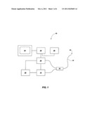
[0013] FIG. 1 is a view of a medical imaging system according to one embodiment of the present invention;
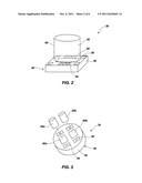
[0014] FIG. 2 is a perspective view of an imaging device according to one embodiment of the present invention;
[0015] FIG. 3 is perspective view of an imaging device according to one embodiment of the present invention;
[0016] FIG. 4 is a side view of a needle having an imaging device disposed therein according one embodiment of the present invention;
[0017] FIG. 5 is a blown up view of the distal end of the needle of FIG. 4;
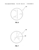
[0018] FIG. 6 is a top view of a slit-valve according to one embodiment of the present invention;
[0019] FIG. 7 is a top view of an orifice valve according to one embodiment of the present invention;
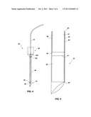
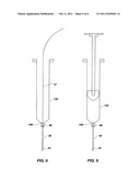
[0020] FIG. 8 is a side view of a syringe connected to the needle of FIG. 4;
[0021] FIG. 9 is a side view of the syringe of FIG. 8 with the imaging device removed;
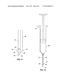
[0022] FIG. 10 is a side view of one embodiment of the present invention with an imaging device disposed on an exterior of a needle; and
[0023] FIG. 11 is a close up view of an imaging device disposed on an exterior of a needle.
[0024] Reference will now be made to the exemplary embodiments illustrated, and specific language will be used herein to describe the same. It will nevertheless be understood that no limitation of the scope of the invention is thereby intended.
DETAILED DESCRIPTION OF EXAMPLE EMBODIMENT(S)
[0025] The following detailed description of exemplary embodiments of the invention makes reference to the accompanying drawings, which form a part hereof and in which are shown, by way of illustration, exemplary embodiments in which the invention may be practiced. While these exemplary embodiments are described in sufficient detail to enable those skilled in the art to practice the invention, it should be understood that other embodiments may be realized and that various changes to the invention may be made without departing from the spirit and scope of the present invention. Thus, the following more detailed description of the embodiments of the present invention is not intended to limit the scope of the invention, as claimed, but is presented for purposes of illustration only and not limitation to describe the features and characteristics of the present invention, to set forth the best mode of operation of the invention, and to sufficiently enable one skilled in the art to practice the invention. Accordingly, the scope of the present invention is to be defined solely by the appended claims.
[0026] The following detailed description and exemplary embodiments of the invention will be best understood by reference to the accompanying drawings, wherein the elements and features of the invention are designated by numerals throughout.
[0027] It must be noted that, as used in this specification and the appended claims, singular forms of "a," "an," and "the" include plural referents unless the context clearly dictates otherwise.
[0028] An "SSID," "solid state imaging device," "SSID chip," or "solid state imaging chip" in the exemplary embodiments generally comprises an imaging array or pixel array for gathering image data. In one embodiment, the SSID can comprise a silicon or other semiconductor substrate or amorphous silicon thin film transistors (TFT) having features typically manufactured therein. Features can include the imaging array, conductive pads, metal traces, circuitry, etc. Other integrated circuit components can also be present for desired applications. However, it is not required that all of these components be present, as long as there is a means of gathering visual or photon data, and a means of sending that data to provide a visual image or image reconstruction.
[0029] The term "umbilical" can include the collection of utilities that operate the SSID or the micro-camera as a whole. An umbilical includes a conductive line, such as electrical wire(s) or other conductors, for providing power, ground, clock signal, and output signal with respect to the SSID, though not all of these are strictly required. For example, ground can be provided by another means than through an electrical wire (e.g., to a camera housing such as micromachined tubing). The umbilical can also include other utilities such as a light source, temperature sensors, force sensors, fluid irrigation or aspiration members, pressure sensors, fiber optics, microforceps, material retrieval tools, drug delivery devices, radiation emitting devices, laser diodes, electric cauterizers, and electric stimulators, for example. Other utilities will also be apparent to those skilled in the art and are thus comprehended by this disclosure.
[0030] "GRIN lens" or "graduated refractive index lens" refers to a specialized lens that has a refractive index that is varied radially from a center optical axis to the outer diameter of the lens. In one embodiment, such a lens can be configured in a cylindrical shape, with the optical axis extending from a first flat end to a second flat end. Thus, because of the differing refractive index in a radial direction from the optical axis, a lens of this shape can simulate the effects of a more traditionally shaped lens. The GRIN lens may be a GRIN rod lens or any other GRIN lens configuration.
[0031] In minimally invasive surgery, a portal is formed in the patient's skin and tools are inserted into the body cavity. For example, in laparoscopic surgery, a rigid laparoscope is passed through the portal created in the patient's skin providing direct visualization inside the body cavity. While the surgeon may have a limited view of the body cavity, a separate device must typically be utilized to deliver medications and/or remove tissues. Advantageously, the present invention allows a medical practitioner to position a needle while simultaneously viewing the area adjacent the tip of the needle without introducing any additional viewing devices other than the device immediately associated with the needle itself. The device also advantageously allows the medical practitioner to strategically deliver fluids and/or aspirate fluids from a patient through a portal no larger than the desired needle diameter (e.g., no greater than 1 millimeter).
[0032] With reference to FIGS. 1 through 3, in one embodiment of the present invention, a medical imaging system 10 comprises an umbilical 12 having an imaging device disposed at a distal tip 15 of the umbilical 12. A processor 22, such as an appropriately programmed computer, is provided to control the imaging system 10 and create an image of anatomy adjacent the distal tip portion 15, within a patient (not shown), displayable on a monitor 24, and storable in a data storage device 26. An interface 28 is provided which supplies power to the imaging device and feeds a digital image signal to the processor based on a signal received from the imaging device via conductive wires 29 through the umbilical 12. A light source 60 may also be provided at the distal end of the umbilical 12. In one aspect, the system further includes a fitting 16 enabling an imaging fluid, such as a clear saline solution, to be dispensed to the distal tip portion of the umbilical 12 from a reservoir 18 through an elongated tubular member (not shown) removably attached to the umbilical 12 to displace body fluids as needed to provide a clearer image. A pump 20 is provided, and is manually actuated by a medical practitioner performing a medical imaging procedure, or can be automated and electronically controlled so as to dispense fluid on demand according to control signals from the practitioner, sensors, or according to software commands.
[0033] Referring now to FIG. 2, an imaging device, indicated generally at 30, includes a GRIN lens 35 and an SSID 40. The SSID 45 can comprise a silicon or other semiconductor substrate or amorphous silicon thin film transistors (TFT) 45 having features typically manufactured therein. Features including the imaging array 50, the conductive pads 55, metal traces (not shown), and circuitry (not shown) can be fabricated therein. With respect to the conductive pads, the connection between conductive pads and a conductive line of an umbilical (not shown) can be through soldering, wire bonding, solder bumping, eutectic bonding, electroplating, and conductive epoxy. However, a direct solder joint having no wire bonding between the electrical umbilical and the conductive pads is also contemplated herein. In one embodiment, the conductive line of the umbilical provides power, ground, clock signal, and output signal with respect to the SSID 40. Other integrated circuit components can also be present for desired applications, such as light emitting diodes (LEDs) 60, for providing light to areas around the GRIN lens 35. It is not required that all of these components be present, as long as there is a visual data gathering and sending image device present, and some means provided to connect the data gathering and sending device to a visual data signal processor. Other components, such as the umbilical, housing, adaptors, utility guides, and the like, can also be present, though they are not shown in FIG. 2. The SSID 40 can be any solid state imaging device, such as a CCD, a CID, or a CMOS imaging device. Also shown, the GRIN lens 35 is coated with an opaque coating 65 on the curved surface to prevent light from entering the lens at other than the flat surface that is most distal with respect to the SSID 40. Additional principles of operation and details of construction of similar imaging device assemblies can be found in U.S. patent application Ser. Nos. 10/391,489, 10/391,490, 11/292,902, and 10/391,513 each of which are incorporated herein by reference in their entireties.
[0034] Referring now to FIG. 3, in one embodiment of the present invention, an imaging device is shown generally at 75 which can provide stereoscopic imaging. Specifically, multiple imaging arrays 80a, 80b, are shown on a common SSID 40 in a coplanar arrangement. A pair of GRIN lenses 35a, 35b are shown as they would be optically coupled to imaging arrays 80a, 80b, respectively. Other than the imaging array, other features are also present in the SSID 40, including conductive pads 55 for providing an electrical connection to an umbilical (not shown).
[0035] With specific reference to FIGS. 1 through 5, in one embodiment of the present invention, a medical apparatus shown generally at 85 is provided comprising a needle 90 having a distal end 91 and a proximal end 92. The proximal end 92 of the needle 90 is configured to be removably connectable to a distal end of a syringe 130 (shown generally in FIG. 8). The apparatus 85 further comprises an umbilical 12 removably inserted within the needle 90 and configured for detachable connection to a data processor 22 and a display device 24. The apparatus 85 further comprises an SSID 40 disposed on a distal end 15 of the umbilical 12 and a lens system 95 disposed on a distal end 41 of the SSID 40. The umbilical 12 is inserted within the needle 90 such that the distal end 96 of the lens system 95 is disposed at approximately the distal end 91 of the needle 90. In one aspect of the invention, the umbilical 12 comprises conductive wires 42 for providing energy to the SSID 40 and/or for transmitting image data from the SSID 40 to the data processor 22. In another aspect of the invention, the umbilical further comprises a light source 43 for illuminating interior portions of the anatomy of the patient. In one aspect of the present invention, the lens system 95 is a single GRIN lens bonded directly to the SSID 40.
[0036] In another embodiment of the invention, the distal end 96 of the lens system 95 is shaped to approximate the shape of the distal end 91 of the needle 90. Advantageously, the distal end 96 of the lens system 95 can be positioned flush with the distal end 91 of the needle 90 but in such a manner that the lens system 95 does not increase patient discomfort by changing the shape of the distal end 91 of needle 90. In one aspect of the invention, the lens system 95 substantially occludes the needle 90. In another aspect, positioning the lens system 95 flush with the distal end 91 of the needle 90 advantageously minimizes image aberration. In yet another aspect, the distal end 91 of the needle 90 is translucent thereby allowing for imaging outside the perimeter of the needle 90.
[0037] With reference now to FIGS. 4 through 7, in another embodiment of the present invention, the medical apparatus 85 further comprises a pressure responsive two-way valve member 100 disposed within the lumen of the needle 90. As the umbilical 12 is removed from the needle, the valve member 100 advantageously minimizes back flow of fluids from the patient back through the needle when the valve member is under pressures normally exerted by fluids in the patient. The valve member 100 is configured such that it allows fluids to be injected through the needle and into the patient upon positive pressure injection from a syringe or other injection device and/or remove fluids from a patient upon negative pressure from a syringe or other fluid removal device. In one aspect of the invention, the pressure responsive two-way valve member 100 is a slit-valve 110. In yet another aspect of the invention, the two-way pressure responsive valve member 100 is an orifice valve 120 disposed in a diaphragm. The valve member 100 is typically biased in a closed position. The diaphragm and/or slit-valve may comprise any polymeric, thermoplastic and/or elastomeric material suitable for preventing backflow of fluids from the body yet opening in a distal and proximal direction to a pre-determined pressure value.
[0038] In yet another embodiment, the needle 90 further comprises a securement device for removably securing the umbilical 12 at a desired position within the needle 90. The securement device can be a miniature compression fitting or any other device suitable for securing the umbilical 12 in place.
[0039] Referring now to FIGS. 10 and 11, in another embodiment, the imaging device 30 may be removably secured on the exterior of needle 90. In yet another embodiment, the imaging device 30 may be permanently attached to the exterior of the needle 90. Advantageously, while secured to an exterior of the needle 90, the imaging device 30 would not need to be removed from the needle in order to inject or aspirate fluids to or from the patient. In one embodiment where the umbilical 12 and imaging device 30 are positioned on an exterior of the needle 90, a distal end of the imaging device 30 is shaped to approximate the shape of the distal end of the needle 90 and positioned on the distal end 91 of the needle 90 such that the face 31 of the imaging device 30 is coplanar (i.e., oriented at the same angle) with the face 92 of the needle 90. In this manner, the penetration of the imaging device 30 and needle 90 into the patient is accomplished without undue discomfort to the patient. In another embodiment, the imaging device 30 is equipped with a piercing member 32 to facilitate penetration into the patient as noted above. The face 33 of piercing member 32 is oriented to match the pitch and orientation of the face 92 of needle 90. In one embodiment of the invention, the piercing member 32 is translucent so as to permit viewing outside the perimeter of the piercing member 32.
[0040] In one aspect of the invention, the umbilical 12 of imaging device 30 is tethered to a data processor which is disposed on a proximal portion of needle 90 or on a syringe. The data processor is capable of powering the imaging device 30 as well as receiving and transmitting image data from the imaging device 30 to a remote system, including a display. In this manner, the imaging device 30 is not tethered to a remote system by the umbilical 12 but retains the ability to receive and transmit image data.
[0041] Referring now to FIGS. 1, 4, 5, 8, and 9, in another embodiment of the present invention, a method of real-time imaging tissue proximate to a distal end 91 of a needle 90 is disclosed comprising advancing a distal end 91 of a needle 90 within a portion of a patient. The needle 90 has an imaging device 30 removably inserted therein comprising an umbilical 12 with an SSID 40 disposed on a distal end of the umbilical 12 and a lens system 95 optically coupled to the SSID 40. The umbilical 12 is detachably connected to a data processor 22 and a display device 24. The method further comprises transmitting image data from the imaging device 30 to the data processor 22 and the display device 24, positioning the distal end 91 of the needle 90 within the patient while viewing the anatomy of the patient on the display device 24, and removing the imaging device 30 from the needle 90. In one embodiment, the method further comprises connecting the needle 90 to a fluid source 16 and injecting a fluid into the patient after removing the imaging device 30 from the needle 90. The method further comprises connecting a syringe 130 to the needle 90 and aspirating fluid from the patient.
[0042] With reference to FIGS. 10 and 11, in another embodiment of the present invention, a method of real-time imaging tissue proximate to a distal end 91 of a needle 90 is disclosed comprising advancing a distal end 91 of a needle 90 within a portion of a patient. The needle 90 has an imaging device 30 disposed on an exterior of the needle comprising an umbilical 12 with an SSID 40 disposed on a distal end of the umbilical 12 and a lens system 95 optically coupled to the SSID 40. The umbilical 12 is detachably connected to a data processor 22 and a display device 24. The method further comprises transmitting image data from the imaging device 30 to the data processor 22 and the display device 24, positioning the distal end 91 of the needle 90 within the patient while viewing the anatomy of the patient on the display device 24. In one embodiment, the method further comprises connecting the needle 90 to a fluid source 16 and injecting a fluid into the patient. The method further comprises connecting a syringe 130 to the needle 90 and aspirating fluid from the patient.
[0043] While the forgoing examples are illustrative of the principles of the present invention in one or more particular applications, it will be apparent to those of ordinary skill in the art that numerous modifications in form, usage and details of implementation can be made without the exercise of inventive faculty, and without departing from the principles and concepts of the invention. Accordingly, it is not intended that the invention be limited, except as by the claims set forth below.
User Contributions:
Comment about this patent or add new information about this topic:
Images included with this patent application:
 |  |
 |  |
 |  |
| New patent applications in this class: | |
| Date | Title |
|---|---|
| 2022-05-05 | Method and apparatus for medical devices under regulatory control |
| 2019-05-16 | System and methods for endoscopic imaging |
| 2019-05-16 | Endoscope device |
| 2019-05-16 | Image processing device, endoscope system, information storage device, and image processing method |
| 2019-05-16 | Endoscopic system for optimized visualization |
| New patent applications from these inventors: | |
| Date | Title |
|---|---|
| 2022-07-07 | Unified robotic vehicle systems and methods of control |
| 2022-06-30 | Coupleable, unmanned ground vehicles with coordinated control |
| 2022-06-30 | Smart control system for a robotic device |
| 2022-01-13 | System, method, and device for facilitating effective decontamination as part of a decontamination event |
| 2022-01-13 | System, method, and device for facilitating effective decontamination as part of a decontamination event |
| Top Inventors for class "Surgery" | |
| Rank | Inventor's name |
|---|---|
| 1 | Roderick A. Hyde |
| 2 | Lowell L. Wood, Jr. |
| 3 | Eric C. Leuthardt |
| 4 | Adam Heller |
| 5 | Phillip John Plante |