Patent application title: Blower designed for fitting particularly in a chamber furnace
Inventors:
Radomir Magiera (Lodz, PL)
Wladyslaw Krllowicz (Lodz, PL)
Krzysztof Jozwik (Lodz, PL)
Jozef Olejnik (Os. Zakow, PL)
Assignees:
SECO/WARWICK S.A.
IPC8 Class: AF04D1900FI
USPC Class:
415220
Class name: Rotary kinetic fluid motors or pumps working fluid passage or distributing means associated with runner (e.g., casing, etc.) casing with axial flow runner
Publication date: 2011-10-06
Patent application number: 20110243728
Abstract:
The blower designed particularly for fitting in a chamber furnace has the
hub of the rotor wheel in the shape of a solid of revolution with its
slant height described by n degree polynomial and its Dp2 outlet
diameter greater than Dp1 inlet diameter and the outward diameter of
the axial and radial rotor wheel with spatially shaped blades
monotonically increasing towards the flow from D1z inlet diameter to D2z
outlet diameter.Claims:
1. The blower designed particularly for fitting in a chamber furnace, in
the form of a rotor wheel with blades set diagonally on the shaft, set in
an enclosure creating an inlet confuser duct, with its bridge with an
approximate angle of 90.degree. behind the rotor wheel, which turns
smoothly into a radial diffuser, behind which it has a bridge shaped with
an approximate angle of 90.degree. ending with a nozzle box with nozzles
wherein the hub of the rotor wheel has the shape of a solid of revolution
with its slant height described by n degree polynomial and its Dp2
outlet diameter greater than Dp1 inlet diameter and the outward
diameter of the axial and radial rotor wheel with spatially shaped blades
monotonically increasing towards the flow from D1z inlet diameter to D2z
outlet diameter.Description:
[0001] This invention relates to a blower designed for fitting in a
chamber furnace in particular and used, among others, in furnaces for
annealing of aluminium sheet.
[0002] In furnaces requiring circulation of hot gases, usually radial or axial blowers are used. The fitting of the latter is subject to significant restrictions that affect their operating parameters. Due to the conditions of the bearings operation, the blowers are usually built as overhung. In order to avoid excessive overhang and unnecessary increase of the furnace chamber size, rotor wheels are fitted close to the chamber wall. This is also the reason for insufficient space for the stationary airfoils, which, in turn, considerably affects the efficiency and flow parameters of the axial blower. Therefore, the parameters of such blowers do not usually exceed the value of pressure difference Ψ equalling 0.2 and the value of flow ψ equalling 0.3.
[0003] As compared to axial blowers, radial blowers used in furnaces ensure considerably greater pressure increments (with Ψ pressure difference exceeding 0.4) however they are burdened with significant defects. First of all, in order to achieve the required pressure increment, the dynamic pressure should be recovered in a reasonably efficient manner. In classic designs of blowers this is done in cumulative spirals with large angles of wrap, i.e. up to 360°. In chamber furnaces, air exhausted from the blower must go in two opposite ways. The use of one or two exhaust spirals is very difficult for structural reasons. In practice this results in an unequal distribution of velocities on both exhaust surfaces of the blower, which is even magnified by existence of a considerable angular momentum of the agent behind the rotor wheel. Such defects are typical of radial and drum blowers.
[0004] The description of the patent No. DE 10022788 presents a solution involving a use of an axial rotor with a constant outward diameter cooperating with two flat diffusers turning into two nozzle boxes. This blower is characterised by the same flow parameters as typical axial blowers, however, it shows much greater pressure increments and ensures an equal flow of the agent in both ways. Additionally, such blowers do not require using additional stators for the purposes of levelling of the field of velocity. However, the circulation efficiency of such blowers is relatively low (0.4). One of the reasons for such a low circulation efficiency is the fact that the agent leaving the axial rotor has a great kinetic energy and, therefore, losses generated in the bridge at the angle of 90° are also considerable, as diffusers operate with a rotational stall at the outlet.
[0005] The invented blower, particularly the one to be fitted in a chamber furnace, in the form of a rotor wheel with blades set diagonally on the shaft, set in an enclosure creating an inlet confuser duct, with its bridge with an approximate angle of 90° behind the rotor wheel, which turns smoothly into a radial diffuser, behind which it has a bridge shaped with an approximate angle of 90° ending with a nozzle box with nozzles is characterised in that the hub of the rotor wheel has the shape of a solid of revolution with its slant height described by n degree polynomial and its Dp2 outlet diameter greater than Dp1 inlet diameter and the outward diameter of the axial and radial rotor wheel with spatially shaped blades monotonically increasing towards the flow from D1z inlet diameter to D2z outlet diameter.
[0006] The presented solution, owing to the shape of the rotor allowing the shaping of the first bridge with a large angle, will enable an increase in the circulation efficiency and, at the same time, maintain the required thermodynamic parameters.
BRIEF DESCRIPTION OF DRAWINGS
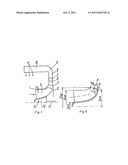
[0007] The invention will be shown on an exemplary drawing, which does not restrict its construction as shown in the drawing, in which FIG. 1 presents a cross-section of the blower on the plane passing through its longitudinal axis and bridge axis, whereas
[0008] FIG. 2 presents a cross-section of the hub and the blade of the rotor wheel.
[0009] On the blower shaft 1 there is a diagonally set rotor wheel 3 with spatially shaped blades 4. The wheel 3 is set in the enclosure 5, creating the inlet confuser duct 6. Behind the rotor wheel 3 the blower has a bridge 7 with an approximate angle of 90°, which turns smoothly into a radial diffuser 8, behind which there is another bridge 9 with an approximate angle of 90°, ending with a nozzle box 10 with nozzles 11. The hub 12 of the rotor wheel 3 has the shape of a solid of revolution with its slant height described by n degree polynomial, with its Dp2 outlet diameter greater than Dp1 inlet diameter and the outward diameter of the axial and radial rotor wheel 3 with spatially shaped blades 4, monotonically increasing towards the flow from D1z inlet diameter to D2z outlet diameter. The rotor wheel 3 is a semi-open wheel without a cover. Between the external contours of the blades 4 and the stationary body of the blower there is gap δ, the size of which depends on mutual thermal dilatation of the wheel 3 and the body. It is also possible to deliver a blower, in which the wheel structure 3 is equipped with a cover.
[0010] The hot air or other gas flows through the stationary duct 6, gaining acceleration of several percent, which favours levelling of the velocity profile on the inlet surface of the rotor wheel 3. The direction of the flow of the agent onto the blades 4 of the rotor wheel 3 is approximately axial. Next, the agent flows through the system of blades 4 of the rotor wheel 3, which conveys energy to the agent in accordance with the basic equation for fluid flow machines (Euler's identity). The agent is subject to compression. The degree of compression depends upon a selection of geometrical parameters of the rotor wheel 3 and its rotating velocity. The agent leaves the rotor wheel 3 at an angle in relation to the rotor rotation axis 3--diagonally. The γ flow-out angle on the meridional plane is described by γ relation <90°. The flow-out angle for the agent leaving the rotor wheel 3 depends on the assumed angle of the blade at the outlet and assumed rotating velocity.
User Contributions:
Comment about this patent or add new information about this topic:
Images included with this patent application:
 |
| New patent applications in this class: | |
| Date | Title |
|---|---|
| 2022-05-05 | Turbo-molecular pump |
| 2017-08-17 | Inlet assembly for a turbofan engine |
| 2016-06-30 | Turbine rotor assembly |
| 2016-05-19 | Turbine |
| 2016-05-05 | Multiple stage fuel pump |
| Top Inventors for class "Rotary kinetic fluid motors or pumps" | |
| Rank | Inventor's name |
|---|---|
| 1 | Gabriel L. Suciu |
| 2 | Frederick M. Schwarz |
| 3 | United Technologies Corporation |
| 4 | Brian D. Merry |
| 5 | Craig M. Beers |