Patent application title: Section for Structures and Relative Structure
Inventors:
Sergio Dallan (Castelfranco Veneto, IT)
Assignees:
DALLAN S.P.A.
IPC8 Class: AE04B918FI
USPC Class:
5250607
Class name: Sheetlike element assembled parallel to existing wall, ceiling, or floor (e.g., insulating panel, sheathing) element spaced from wall, ceiling, or floor and held by discrete retaining means (e.g., suspended ceiling or wall) inverted t-bar type
Publication date: 2011-10-06
Patent application number: 20110239575
Abstract:
A section with a "T" profile comprising a rib and a plate which extends
from a first to a second end. The section having, in proximity of at
least one of said ends, a coupling element suitable to engage with a
further section, and the rib comprising at least one engagement aperture
shaped to house said coupling element. Advantageously, the coupling
element comprises an attachment base to the rib which projects at least
partially from the section with a free end, and a tongue elastically
flexible and connected to the attachment base. The tongue is bent towards
the attachment base at said free end so as to form an angle of incidence
with the attachment base, and is provided with a coupling hole suitable
to engage with at least a first tooth of the engagement aperture.Claims:
1. Section in particular for structures, having a main longitudinal
extension from a first to a second end, the section having, in proximity
of at least one of said ends, a coupling element suitable to engage with
a further section, the section comprising a rib and a plate positioned
perpendicular to the rib so as to form an overall "T" section, the rib
comprising at least one engagement aperture shaped to house said coupling
element, the engagement aperture being positioned between said first and
second ends, wherein the coupling element comprises an attachment base to
the rib which projects at least partially from the section with a free
end, and a tongue elastically flexible and connected to the attachment
base, the tongue being bent towards the attachment base at said free end
so as to form an angle of incidence with the attachment base, the tongue
being provided with a coupling hole, the engagement aperture defining at
least a first tooth suitable to engage with the coupling hole of the
tongue.
2. Section according to claim 1, wherein the engagement aperture has a first pair of guides positioned on opposite sides to the first tooth, and said coupling element has a first pair of tabs overhanging the attachment base, said first guides co-operating so as to slide with the first tabs to guide the engagement of the coupling element.
3. Section according to claim 1, wherein the engagement aperture defines at least a second tooth, opposite the first tooth in relation to a centreline plane of the engagement aperture orthogonal to the main longitudinal extension, to permit the contemporary restraint of two coupling elements of two separate sections.
4. Section according to claim 3, wherein said centreline plane is also a plane of symmetry for the engagement aperture.
5. Section according to claim 3, wherein the engagement aperture has a second pair of guides positioned on opposite sides to the second tooth, to permit the guided engagement of two coupling elements of two separate sections.
6. Section according to claim 1, wherein the attachment base is attached to the rib by riveting, welding, gluing and/or threaded connection means.
7. Section according to claim 1, wherein the free end of the attachment base has a pair of shoulders which define a limit stop in the insertion of the attachment element inside the engagement aperture, said shoulders abutting against the rib.
8. Section according to claim 1, wherein the free end has a pair of bevelled drafts to facilitate insertion of the attachment element inside the engagement aperture.
9. Section according to claim 1, wherein said rib, on the side opposite the plate, comprises a longitudinal stiffening element.
10. Structure, in particular to support false ceilings, comprising a plurality of sections according to claim 1, wherein said sections are mechanically connected to each other so that the attachment element of a first section engages in the engagement aperture of a second section.
Description:
FIELD OF THE INVENTION
[0001] The present invention relates to a section for structures, preferably of false ceilings and a relative structure.
BACKGROUND OF THE INVENTION
[0002] It is known of in the art to make structures for false ceilings comprising a plurality of sections mechanically coupled to each other.
[0003] The sections of the prior art have a "T" profile comprising a central rib, a plate perpendicular to the central rib, and coupling elements positioned on the lateral ends of the rib.
[0004] The coupling elements engage mechanically on dedicated apertures made on the central rib.
[0005] The solutions of the prior art are rather complex and expensive to produce.
SUMMARY OF THE INVENTION
[0006] The purpose of the present invention is to overcome the drawbacks and limitations of the solutions of the prior art and, in particular, to provide a section which is simple and economical to produce which ensures reliable assembly.
[0007] Such purpose is achieved by a section according to claim 1 and by a structure according to claim 10.
[0008] Other embodiments of the present invention are described in the remaining claims.
BRIEF DESCRIPTION OF THE DRAWINGS
[0009] Further characteristics and advantages of the present invention will be clearly comprehensible from the description given below of its preferred embodiments, made by way of a non-limiting example, wherein:
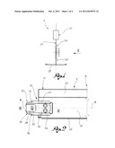
[0010] FIG. 1 shows a side view of a section according to one embodiment of the present invention;
[0011] FIG. 2 shows a side view of the section in FIG. 1, from the side shown by the arrow II in FIG. 1;
[0012] FIG. 3 shows a cross-section view of the section in FIG. 1, along the section plane III-III in FIG. 2;
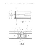
[0013] FIG. 4 shows a view of a structure comprising sections according to the present invention;
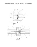
[0014] FIG. 5 shows a cross-section view of the structure in FIG. 4, along the section plane V-V in FIG. 4;
[0015] FIG. 6 shows a cross-section view of the structure in FIG. 4, along the section plane V-V in FIG. 4;
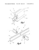
[0016] FIG. 7 shows a perspective view of the section illustrated in FIG. 1;
[0017] FIG. 8 shows a perspective view of three sections according to the invention in an assembly position.
DETAILED DESCRIPTION OF THE INVENTION
[0018] The elements or parts of elements common to the embodiments described below will be indicated using the same reference numerals.
[0019] With reference to the aforesaid drawings, reference numeral 4, 4' globally denotes a section, in particular for structures 8, having a main longitudinal extension X-X from a first to a second end 12, 16.
[0020] The section 4 has, in proximity of at least one of said ends 12, 16, a coupling element 20 suitable to engage with a further section 4''.
[0021] The section 4 comprises a rib 24 and a plate 28 positioned perpendicular to the rib 24 so as to form an overall "T" section.
[0022] Preferably the rib 24, on the side opposite the plate 28, comprises a longitudinal stiffening element 42.
[0023] The rib 24 comprises at least one engagement aperture 36 shaped to house said coupling element 20 and positioned between said first and second ends 12,16.
[0024] The coupling element 20 comprises an attachment base 40 to the rib 24 which projects at least partially from the section 4 with a free end 44, and a tongue 48 elastically flexible and connected to the attachment base 40.
[0025] For example, the attachment base 40 is attached to the rib by riveting, welding, gluing and/or threaded connection means.
[0026] Advantageously, the tongue 48 is bent towards the attachment base 40, at said free end 44 so as to form an angle of incidence with the attachment base 40.
[0027] The tongue 48 is provided with a coupling hole 52, and the engagement aperture 36 defines at least a first tooth 56 suitable to engage with the coupling hole 52 of the flexible tongue 48.
[0028] According to one embodiment, the engagement aperture 28 has a first pair of guides 60 positioned on opposite sides to the first tooth 56, and said coupling element 20 has a first pair of tabs 64 overhanging the attachment base 40; said guides 60 co-operate so as to slide with the tabs 64 to guide the engagement of the coupling element 20.
[0029] According to a further embodiment, the engagement aperture 36 defines at least a second tooth 68, opposite the first tooth 56 in relation to a centreline plane M-M of the engagement aperture 36 orthogonal to the main longitudinal extension X-X, to permit the contemporary restraint of two coupling elements 20 of two separate sections 4', 4''.
[0030] According to a further embodiment, the engagement aperture 36 has a second pair of guides 72 positioned on opposite sides to the second tooth 68, to permit the guided engagement of two coupling elements 20 of two separate sections 4', 4''.
[0031] Preferably, said centreline plane M-M is also a plane of symmetry for the engagement aperture 36.
[0032] The free end 44 of the attachment base 40 preferably has a pair of shoulders 76 which define a limit stop in the insertion of the attachment element 20 inside the engagement aperture 36, said shoulders 76 abutting against the rib 24.
[0033] The free end 44 may have a pair of bevelled drafts 80 to facilitate insertion of the attachment element 20 inside the engagement aperture 36.
[0034] The sections 4, 4', 4'' of the present invention may advantageously be assembled to each other to form a structure 8, in particular to support false ceilings.
[0035] Said structure 8 (FIGS. 4, 6) comprises a plurality of sections 4, 4',4'' mechanically connected to each other so that the attachment element 20 of a first section 4' engages in the engagement aperture 36 of a second section 4''.
[0036] As may be appreciated from the description, the section according to the invention makes it possible to overcome the drawbacks presented in the prior art.
[0037] In particular, the section is economical and simple to produce.
[0038] In addition, the section guarantees a reliable mechanical connection and stability of the structure obtained by the interconnection of such sections.
[0039] A person skilled in the art may make numerous modifications and variations to the sections described above so as to satisfy contingent and specific requirements, all contained within the sphere of the invention as defined by the appended claims.
User Contributions:
Comment about this patent or add new information about this topic:
| People who visited this patent also read: | |
| Patent application number | Title |
|---|---|
| 20180170787 | Arrangement For Realizing The Vacuum Operation In The Moulding Process Of A Glass Moulding Machine |
| 20180170785 | Method for Separating Liquid From Suspended Matter in a Sludge and Device for Same |
| 20180170782 | WASTE MATERIAL PROCESS AND PRODUCT |
| 20180170781 | DIGESTION OF ELEMENTAL SULFUR IN BIOREACTOR DURING BIOLOGICAL OXIDATION OF SULFIDE IN WASTEWATER AND GROUNDWATER |
| 20180170780 | PROCESSING METHOD FOR WASTE HYDROGEN PEROXIDE AQUEOUS SOLUTION THAT HAS A CONCENTRATION FROM 0.5% TO 90% |
Images included with this patent application:
 |  |
 |  |
| Similar patent applications: | |
| Date | Title |
|---|---|
| 2011-10-06 | Section for structures and relative structure |
| 2010-04-29 | Lightweight construction having a fractally structured supporting structure |
| 2009-08-27 | Double floor type inducing waterproof structure and green roof structure using the same |
| 2009-04-16 | Step for modular staircases and relative staircase |
| 2009-01-15 | Method of reinforcement of a structure and structure thus reinforced |
| New patent applications in this class: | |
| Date | Title |
|---|---|
| 2022-05-05 | Ceiling tile control and grid support clip |
| 2019-05-16 | A false ceiling system |
| 2016-06-16 | Ceiling system |
| 2016-05-19 | Ceiling system |
| 2016-04-14 | Free span ceiling grid system |
| New patent applications from these inventors: | |
| Date | Title |
|---|---|
| 2020-04-16 | Apparatus for laser or plasma cutting of pieces of laminar material |
| 2014-11-13 | Inverted t main runner for forming support structures for false ceilings |
| 2012-04-12 | Profiled bar for frames and relative frame |
| 2012-04-12 | Profiled bar for frames and relative frame |
| Top Inventors for class "Static structures (e.g., buildings)" | |
| Rank | Inventor's name |
|---|---|
| 1 | Darko Pervan |
| 2 | Gregory F. Jacobs |
| 3 | Husnu M. Kalkanoglu |
| 4 | Ronald P. Hohmann, Jr. |
| 5 | Mark Cappelle |