Patent application title: METHOD AND APPARATUS TO ADJUST RECEIVED SIGNAL
Inventors:
Assaf Kasher (Haifa, IL)
IPC8 Class: AH04W8402FI
USPC Class:
370338
Class name: Communication over free space having a plurality of contiguous regions served by respective fixed stations contiguous regions interconnected by a local area network
Publication date: 2011-09-29
Patent application number: 20110235622
Abstract:
A wireless communication device, a wireless communication system and a
method to adjust transmitted signals constellation in a maximum
likelihood multiple-input-multiple-output receiver by transmitting an EVM
deviation value. The EVM deviation value may be added to a pre-stored
error value at the receiver.Claims:
1. A method comprising: measuring a noise level value; and transmitting
the noise level value indicating a quality of the noise level in relation
to a required noise level for a transmitted constellation of data
streams.
2. The method of claim 1, wherein transmitting the noise level value comprises: transmitting a deviation of an error vector magnitude value (EVM) in a field of a frame.
3. The method of claim 2, comprising: estimating an estimated EVM from a received signal; calculating an EVM deviation value from a pre-stored EVM value and the estimated EVM; and transmitting the deviation value with the field of the frame.
4. A method of adjusting a received signal in a multiple-input-multiple-output receivers system, the method comprising: receiving a deviation of an error vector magnitude (EVM) value with a received data stream; detecting a symbol from the received data stream using a maximum likelihood detection scheme; adding the deviation EVM value to a pre-stored EVM value; and placing the symbol on a desired constellation point.
5. The method of claim 4, wherein receiving comprises: receiving a frame that include the deviation EVM value.
6. The method of claim 4, comprising: receiving a modulation coding scheme and adding the EVM deviation value to a pre-stored EVM value according to the modulation coding scheme.
7. The method of claim 4 comprising: adjusting the received signal for transmitter noise by adding the deviation EVM value to a pre-stored EVM value in order to place the symbol on a desired constellation point.
8. A wireless communication device comprising: a multiple-input-multiple-output (MIMO) receivers system to receive a deviation of an error vector magnitude (EVM) value with a received data stream; and a detector to detect a symbol from the received data stream using a maximum likelihood detection scheme and to add the deviation EVM value to a pre-stored EVM value and placing the symbol on a desired constellation point.
9. The wireless communication device of claim 8, wherein the MIMO receivers system is able to receive a frame that includes the deviation EVM value.
10. The wireless communication device of claim 9 wherein the frame includes a modulation coding scheme and the detector is able to add the EVM deviation value to a pre-stored EVM value according to the modulation coding scheme.
11. The wireless communication device of claim 8 comprising: a memory to store in a table the pre stored EVM value, wherein: the detector is able to adjust the received signal for a transmitter noise by adding the deviation EVM value to the pre-stored EVM value from the table in order to place the symbol on a desired constellation point.
12. The wireless communication device of claim 8 wherein the detector comprises a maximum likelihood detector.
13. The wireless communication device of claim 11 wherein the transmitter noise comprises white noise.
14. A wireless communication system comprising: an antenna array operably coupled to a multiple-input-multiple-output (MIMO) receivers system to receive a deviation of an error vector magnitude (EVM) value with a received data stream; and a detector to detect a symbol from the received data stream using a maximum likelihood detection scheme and to add the deviation EVM value to a pre-stored EVM value in order to place the symbol on a desired constellation point.
15. The wireless communication system of claim 14, wherein the MIMO receivers are able to receive a frame that includes the deviation EVM value.
16. The wireless communication system of claim 15 wherein the frame includes a modulation coding scheme and the detector is able to add the EVM deviation value to a pre-stored EVM value according to the modulation coding scheme.
17. The wireless communication system of claim 14 comprising: a memory to store in a table the pre stored EVM value; wherein the detector is able to adjust the received signal for transmitter noise by adding the deviation EVM value to the pre-stored EVM value from the table in order to place the symbol on a desired constellation point.
18. The wireless communication system of claim 14 wherein the detector comprises a maximum likelihood detector.
19. The wireless communication system of claim 14 wherein the transmitter noise comprises white noise.
20. The wireless communication system of claim 14 is able to operate within a wireless local area network using Orthogonal Frequency-Division Multiplexing (OFDM) scheme.
Description:
BACKGROUND OF THE INVENTION
[0001] Wireless local area network (WLAN) devices may include a Multiple-Input-Multiple-Output (MIMO) transmitter receiver system. A Maximum Likelihood (ML) MIMO receiver may not know the transmitter Error Vector Magnitude (EVM). This may result degradation at the performance of the ML receiver, at least but not limited to, the 3×3 and higher MIMO modulations.
[0002] A problem with a MIMO communication may be as follows (the following is a simplified model): a transmitter of the MIMO may transmit a vector x. Each element in the vector is a member of a set of a (linear) digital modulation such as, for example a Binary Phase Shift Keying (BPSK), Quadrature Phase Shift Keying (QPSK), 16-Quadrature amplitude modulation (QAM), 64-QAM or the like.
[0003] A receiver of the MIMO is able to receive a set of receive channels y. The transmitted vector x passes through a matrix representing a channel H. The matrix H includes a plurality of rows k and a plurality of columns l. Each element in the row k and the column l represents the channel between the l' th transmit antenna to the k'th receive chain.
[0004] At the receiver, Gaussian noise n is added to the received signal. The mathematical model is therefore y=Hx+n. A Maximum Likelihood receiver tries to find a transmitted constellation point to generate the highest likelihood for the receive signal:
x ^ = arg x min 1 ( 2 π ) k / 2 σ k exp ( 1 2 σ 2 ( y - Hx ) H ( y - Hx ) ) . ##EQU00001##
This is equivalent to {circumflex over (x)}=argxmin∥y-Hx∥.
[0005] The model described above ignores the transmitter noise which is mostly generated from phase noise and power amplifier non-linearity. The disregard for the transmitter noise may cause the ML receiver to place the transmitted constellation point on an error constellation point of a constellation diagram.
[0006] The received signal is depicted as y=H(x+nT)+nR. The noise at the receiver is colored and the maximum likelihood search is depicted as
x ^ = arg x min 1 ( 2 π ) k / 2 R n 1 / 2 exp ( - 1 2 ( y - Hx ) H R n - 1 ( y - Hx ) ) . ##EQU00002##
Where Rn is the combined noise covariance matrix at the ML receiver (for example Gaussian noise of the transmitter). Rn=σR2I+σT2HHH where, σR2 is the noise variance at each of the receiver chains, as measured at the receiver and σT2 is the transmitter noise variance, as measured at the transmitter antenna ports. While H is estimated during packet preamble analysis at the ML receiver, the ratio between σR2 and σT2 is not known to the ML receiver and may impair the ML receiver performance. Thus, there is a need to mitigate the above described problems.
BRIEF DESCRIPTION OF THE DRAWINGS
[0007] The subject matter regarded as the invention is particularly pointed out and distinctly claimed in the concluding portion of the specification. The invention, however, both as to organization and method of operation, together with objects, features and advantages thereof, may best be understood by reference to the following detailed description when read with the accompanied drawings in which:
[0008] FIG. 1 is a schematic illustration of a wireless communication system according to exemplary embodiments of the present invention;
[0009] FIG. 2 is a schematic illustration of a packet according to exemplary embodiment of the invention;
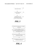
[0010] FIG. 3 is a flow chart of a method of transmitting EVM deviation value at a wireless communication device according to some embodiments of the present invention; and
[0011] FIG. 4 is a flow chart of a method of receiving a constellation of data streams to some embodiments of the invention.
[0012] It will be appreciated that for simplicity and clarity of illustration, elements shown in the figures have not necessarily been drawn to scale. For example, the dimensions of some of the elements may be exaggerated relative to other elements for clarity. Further, where considered appropriate, reference numerals may be repeated among the figures to indicate corresponding or analogous elements.
DETAILED DESCRIPTION OF EMBODIMENTS OF THE INVENTION
[0013] In the following detailed description, numerous specific details are set forth in order to provide a thorough understanding of the invention. However it will be understood by those of ordinary skill in the art that the present invention may be practiced without these specific details. In other instances, well-known methods, procedures, components and circuits have not been described in detail so as not to obscure the present invention.
[0014] Some portions of the detailed description, which follow, are presented in terms of algorithms and symbolic representations of operations on data bits or binary digital signals within a computer memory. These algorithmic descriptions and representations may be the techniques used by those skilled in the data processing arts to convey the substance of their work to others skilled in the art.
[0015] Unless specifically stated otherwise, as apparent from the following discussions, it is appreciated that throughout the specification discussions utilizing terms such as "processing," "computing," "calculating," "determining," or the like, refer to the action and/or processes of a computer or computing system, or similar electronic computing device, that manipulates and/or transforms data represented as physical, such as electronic, quantities within the computing system's registers and/or memories into other data similarly represented as physical quantities within the computing system's memories, registers or other such information storage, or transmission devices. The terms "a" or "an", as used herein, are defined as one, or more then one. The term plurality, as used herein, is defined as two, or more than two. The term another, as used herein is defined as at least a second or more. The terms including and/or having, as used herein, are defined as, but not limited to, comprising. The term operably coupled, is defined as operably connected in any desired form for example, mechanically, electronically, digitally, directly, by software, by hardware and the like.
[0016] According to embodiments of the present invention, the term EVM (which may be also called receive/transmit constellation error (RCE)) may be defined as a measure used to quantify the performance of the transmitter and/or receiver. The EVM measure may provide an indication of how far transmitter constellation points are from the ideal locations when representing a transmit signal without noise and/or distortion. An ideal transmitter EVM may be measured at the factory and may be stored in a memory for use with embodiment of the invention.
[0017] An error vector is a vector in the In-phase-Quadrature-phase (I-Q) plane between the ideal constellation point and the point received by the receiver. In other words, it is the difference between actual received symbols and ideal symbols. The average power of the error vector, normalized to signal power, is the EVM.
[0018] Furthermore, EVM, as defined for multi carrier modulations, is a ratio of two mean powers and is insensitive to the constellation geometry. In this form, the EVM may be related to modulation error ratio, the ratio of mean signal power to mean error power.
[0019] A constellation diagram is a representation of a signal modulated by a digital modulation scheme such as, for example a quadrature amplitude modulation, a phase-shift keying or the like. The constellation diagram may display the transmitted signal as a two-dimensional scatter diagram in the complex plane at symbol sampling instants. In some the embodiments of the invention, constellation diagrams may be used to recognize the type of interference and distortion in the transmitter signal, if desired.
[0020] For example, maximum likelihood detection upon reception of the transmitted signals may be used. For example, a demodulator may examine a received symbol, which may have been corrupted by a channel and/or a receiver noise. The corruption may be caused, for example, by an additive white Gaussian noise, a distortion, a phase noise an interference or the like. The demodulator may estimate a point on the constellation diagram which is closest to that of the received symbol in order to detect what was actually transmitted. Thus, according to one embodiment of the invention, the receiver may adjust the received signal according to the transmitter EVM deviation value, if desired.
[0021] For the purpose of analyzing received signal quality, some types of corruption are evident in the constellation diagram. For example, a Gaussian noise is shown as fuzzy constellation points, a Non-coherent single frequency interference is shown as circular constellation points, a Phase noise is shown as rotationally spreading constellation points, although the scope of the present invention is not limited in this respect.
[0022] It should be understood that embodiments of the present invention may be used in a variety of applications. Although the present invention is not limited in this respect, the circuits and techniques disclosed herein may be used in many apparatuses such as stations of a radio system. Stations intended to be included within the scope of the present invention include, by way of example only, wireless local area network (WLAN) stations, wireless personal network (WPAN), and the like.
[0023] Types of WLAN stations intended to be within the scope of the present invention include, although are not limited to, mobile stations, access points, stations for receiving and transmitting spread spectrum signals such as, for example, Frequency Hopping Spread Spectrum (FHSS), Direct Sequence Spread Spectrum (DSSS), Complementary Code Keying (CCK), Orthogonal Frequency-Division Multiplexing (OFDM) and the like.
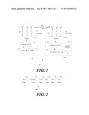
[0024] Turning first to FIG. 1, a schematic illustration of a wireless communication system 100, according to exemplary embodiments of the invention is shown. According to one example embodiment, wireless communication system 100 may employ a WLAN. WLAN 100 may operate according to the standard developing by the IEEE 802.11.ac or the like.
[0025] According to this exemplary embodiment of the invention, WLAN 100 may include, but is not limited to including, a multiple-input-multiple-output (MIMO) transmitter 110, and MIMO receiver 150. MIMO transmitter 110 may include noise estimator 111, an EVM deviation value generator 113, a modulator 115, a MIMO 117, antennas 120 which receive a transmitter noise 130. MIMO receiver 150 may include a maximum likelihood (ML) detector 151, a demodulator 157, a calibration error table 157, a MIMO 155, antennas 160 which may receive noise 170.
[0026] For example antennas 120 may include three (3) antennas and antennas 160 may include three (3) antennas. The antennas may be dipole antennas, internal antennas, Yagi antennas, an antenna array or the like.
[0027] According to one embodiment of the invention, MIMO transmitter 110 may estimate a transition noise (e.g., TX noise 130) by noise estimator 111. EVM deviation value generator 113 may calculate an EVM deviation value by, for example, submitting the noise estimate from a pre-stored noise measure. For example, the pre-stored noise measurement may be stored in a table similar to error table 158 (not shown), if desired. Furthermore, EVM deviation value generator 113 may generate a frame and/or data packets which include the EVM deviation value.
[0028] According to exemplary embodiments of the invention, modulator 115 may be an Orthogonal Frequency Division Multiplexing (OFDM) modulator and/or Orthogonal Frequency Division Multiple Access (OFDMA) modulator or the like. Modulator 115 may modulate the data packet to a transmission vector x wherein each element in the vector x be a member of a set of a (linear) digital modulation such as, for example, a BPSK, QPSK, 16-QAM, 64-QAM or the like. MIMO 117 may transmit the vector x by antennas 120 over channel H 140. The transmitted vector x may include transmit (TX) noise 130 and may depicted as x=x+nt wherein n depict the noise.
[0029] Although the scope of the present invention is not limited to this exemplary embodiment, antennas 160 may receive the transmitted signal with additional receive (RX) noise 170. The received signal may include at least the data packet which includes the EVM deviation value, if desired. The received signal may be depicted as y=Hx++Hnt+nr, wherein H depicts the channel matrix, x is the transmitted signal nt is the transmitter noise and nr is the receiver noise. MIMO receivers 155 may receive the received signal. Demodulator 153 may demodulate the received signal and may provide symbols of the data packet.
[0030] According to embodiments of the present invention ML detector 151 may perform a maximum likelihood (ML) search on the received matrix according to {circumflex over (x)}=argxmin∥r-Hx∥2. For example the noise may be white noise and the noise covariance matrix may be Rn=HHHσt2+Hσr2. Thus, adding the noise to the ML search equation is depicted as
x ^ = arg x min R - 1 2 r - R - 1 2 Hx 2 , ##EQU00003##
although the scope of the present invention is not limited in this respect.
[0031] ML detector 151 is operably coupled to memory 157 which may store exemplary table 1 below. According to this example, Table 1 may be presorted in memory 157 during a device calibration for example in a factory. Exemplary Table 1 shows the allowed relative constellation error versus constellation size and coding rate, if desired.
TABLE-US-00001 TABLE 1 Modulation Coding Rate Relative constellation error (dB) BPSK 1/2 -5 QPSK 1/2 -10 QPSK 3/4 -13 16-QAM 1/2 -16 16-QAM 3/4 -19 64-QAM 2/3 -22 64-QAM 3/4 -25 64-QAM 5/6 -28 256-QAM 2/3 -28 256-QAM 3/4 -31 256-QAM 5/6 -34
[0032] ML detector 151 may receive the EVM deviation value and may add it to the relative constellation error value stored in table 1, although the scope of the present invention is not limited to this example.
[0033] In order to estimate Rn, according to Rn=HHHσt2+Hσr2, ML detector 151 may estimate σT2 (e.g. transmitter noise) using the EVM, although the scope of the present invention is not limited to this example.
[0034] Turning to FIG. 2, a schematic illustration of a frame 200 according to exemplary embodiment of the invention is shown. According to this example frame 200 may include Modulation and Coding Scheme (MCS) field 201 that include 8 bits, a coding field 203 that include 1 bit, an EVE field 204 which include the EVM deviation value of 3 bits, Reserve field 206, Cyclic Redundancy Check (CRC) field of 4 bits for checking errors in the frame and a tail field 209 of 6 bits, although it should be understood that this frame is an example only and other frames with other data may be used with embodiments of the invention.
[0035] Turning to FIG. 3, a flow chart of a method of transmitting EVM deviation value at a wireless communication device according to some embodiments of the present invention is shown. According to this exemplary method a MIMO transmitter (e.g., transmitter 110) may measure a noise level value indicating a quality of the noise level. The transmitter may transmit the noise level value indicating a quality of the noise level in relation to a required noise level for a transmitted constellation of data streams. The MIMO transmitter may measure before each transmission a transmission noise (e.g., TX noise 130) as shown at text box 310. The transmitter may calculate EVM deviation value by, for example, comparing the measured noise to a stored noise values (text box 320), if desired. The transmitter may enter the calculated EVM deviation value to a frame field (e.g., EVM field 204) and transmitted the frame to a ML MIMO receiver e.g., receiver 150 (text box 330).
[0036] It should be understood that according to some embodiment of the invention the EVM deviation value is transmitted in each transmission to the ML MIMO receiver in order to correct error in the signal which caused by the noise and/or to filter the noise. According to embodiments of the invention the noise may be a white noise a Gaussian noise or the like.
[0037] Turning to FIG. 4, a flow chart of a method of receiving a constellation of data streams to some embodiments of the invention is shown. The method starts with receiving signals using a LM MIMO receiver (text box 410). The signals may be OFDM signals and may include data packets which include frames. The ML MIMO receiver (e.g. receiver 150) may decode from the received signal the frame which include the EVM deviation value (text box 420). The ML MIMO decoder may adjust the received signals according to the transmitter EVM (text box 430) for example, by receiving a Modulation and Coding Scheme (MCS) (e.g., field 201) and adding the EVM deviation value to a pre-stored EVM value according to the MCS for placing a detected symbol on a desired constellation point, if desired.
[0038] In addition, the ML MIMO receiver may perform ML detection and/or search on the received frame in order to detect data symbols (text box 440). For example, the constellation point values and/or error values may be stored in a table such as, for example table 1 above. Advantageously, the result of the method is detection without errors the symbols of the received data packet which may enable the transmitter to transmit at a faster data rate and/or less robust modulation schemes, although other advantage may be achieved by using embodiment of the invention.
[0039] While certain features of the invention have been illustrated and described herein, many modifications, substitutions, changes, and equivalents will now occur to those skilled in the art. It is, therefore, to be understood that the appended claims are intended to cover all such modifications and changes as fall within the true spirit of the invention.
User Contributions:
Comment about this patent or add new information about this topic:
Images included with this patent application:
 |  |
| Similar patent applications: | |
| Date | Title |
|---|---|
| 2009-05-28 | Methods and apparatus for generating and processing transmitter signals |
| 2008-12-25 | Method and apparatus to enable multiple receivers |
| 2008-10-02 | Method, system and apparatus for providing rules-based restriction of incoming calls |
| 2008-10-30 | Methods and apparatus to cancel noise using a common reference wire-pair |
| 2009-02-12 | Methods and apparatus for in-order delivery of data packets during handoff |
| New patent applications from these inventors: | |
| Date | Title |
|---|---|
| 2022-09-01 | Mimo and bandwidth signaling in millimeter-wave systems |
| 2022-08-04 | Transmit opportunity continuation timeout for directional multi-gigabit networks |
| 2022-06-30 | System for multistatic radar communication |
| 2021-11-11 | Mimo and bandwidth signaling in millimeter-wave systems |
| 2021-11-11 | System for multistatic radar communication |
| Top Inventors for class "Multiplex communications" | |
| Rank | Inventor's name |
|---|---|
| 1 | Peter Gaal |
| 2 | Wanshi Chen |
| 3 | Tao Luo |
| 4 | Hanbyul Seo |
| 5 | Jae Hoon Chung |