Patent application title: DC brushless motor drive circuit with current variable-voltage
Inventors:
Tai-Her Yang (Dzan-Hwa, TW)
IPC8 Class: AH02P2706FI
USPC Class:
3184003
Class name: Synchronous motor systems brushless motor closed-loop control power supply voltage feature (e.g., power supply voltage, vcc compensation, rectifier circuit, power regulator, auxiliary or secondary power supply, etc.)
Publication date: 2011-09-22
Patent application number: 20110227517
Abstract:
For the present invention, under various running speeds statuses, the
voltage supplied to the DC brushless motor is relatively increased or
decreased on the basis of the internal setting of the motor drive control
device with the increased or decreased load current, to prevent the
shortcoming of too much change of the input impedance caused by the
inductive reactance of the winding accordingly changed when the speed of
the DC brushless motor is changed with the change of the load,
specifically, to prevent the shortcoming of unable to produce required
torque resulting from the increased inductive reactance of the winding
caused by increasing the rotational speed which makes the current value
become too low when input by the original working voltage.Claims:
1. A DC brushless motor drive circuit with current variable-voltage,
which is related to a drive circuit of the DC brushless motor driven by
DC electric power and equipped with the electric machinery angle position
detection device, in which the DC brushless motor is under various
rotational speeds statuses produced on the basis of the magnitude of the
input voltage and the load, through the load current detection device
detecting the variation of the current, and the voltage input into the DC
brushless motor is relatively increased or decreased according to the
internal setting of the motor drive control device, the main components
including: DC brushless motor (101): constituted by the first electric
machinery structure composed of the magnetic field winding and the
magnetic circuit, and the second electric machinery structure composed of
the permanent magnetic pole or the winding excitation type magnetic pole,
in which the first electric machinery structure and the second electric
machinery structure are driven by the relative revolution through the
electric machinery effect between the both, the DC brushless electric
machinery is installed with the motor electric machinery angle position
detection device (103) for detecting the winding of the first electric
machinery structure and the magnetic pole of the second electric
machinery structure, and the detected signal is transmitted to the motor
drive control device (201) for being the reference of controlling the
operation of DC brushless motor (101); motor load current detection
device (102): constituted by the current detection device composed of
electromagnetic sensing method or impedance method, for detecting the
value of the load current transmitted from the motor drive control device
(201) to the DC brushless motor (101); motor electric machinery angle
position detection device (103): constituted by the Hall element with
magnetoelectric effect, or electric machinery angle position detection
device with photoelectric effect or electromagnetic induction effect, or
electromechanical electric machinery angle position detection device, to
be installed at the DC brushless motor (101), for being placed between
the first electric machinery structure equipped with magnetic field
winding and the second electric machinery structure equipped with
permanent magnetic pole or winding excitation type magnetic pole, to
detect the electric machinery angle position between the magnetic field
winding and the permanent magnetic pole or the winding excitation type
magnetic pole placed at another electric machinery structure with
relative coaxial revolution, in which the signal is transmitted to the
motor drive control device (201), for being the reference of controlling
the operation of DC brushless motor (101); motor drive control device
(201): constituted by the electromechanical circuit device, and/or the
solid state electronic device, and/or the microprocessor and related
software, which is a circuit device performing linear or chopper type
voltage regulation on DC electric energy; in which, the motor drive
control device (201) is arranged for inputting DC power, being controlled
by the running operation device (301), and receiving the signals from the
motor electric machinery angle position detection device (103) and the
motor load current detection device (102), for referring the feedback
gain setting of the internal setting of the motor drive control device
(201), to implement the control over the excitation phase sequence of
magnetic field winding of the DC brushless motor (101), the ON/OFF
control, and the control over the excitation voltage, the excitation
current, the direction of the excitation current, and the excitation
timing through the linear control method or the pulse width modulation
method; and running operation device (301): constituted by the operation
device including electromechanical or electronic switch, button,
adjustable potentiometer, keyboard, and indicator, or constituted by the
interface receiving the electric power signal, for controlling the motor
drive control device (201), and further controlling the DC brushless
motor (101).
2. The DC brushless motor drive circuit with current variable-voltage as claimed in claims 1, in which the motor drive control device (201) and the running operation device (301) are integrated.
3. The DC brushless motor drive circuit with current variable-voltage as claimed in claims 1, in which the motor drive control device (201) and the running operation device (301) are individually constituted.
Description:
BACKGROUND OF THE INVENTION
[0001] (a) Field of the Invention
[0002] For the DC brushless motor drive circuit with current variable-voltage of the present invention, in which, under various running speeds statuses, the voltage supplied to the DC brushless motor is relatively increased or decreased on the basis of the internal setting of the motor drive control device according to the increased or decreased load current, so as to prevent the shortcoming of too much change of the input impedance caused by the inductive reactance of the winding accordingly changed when the speed of the DC brushless motor is changed with the change of the load, specifically, to prevent the shortcoming of unable to produce required torque resulting from the increased inductive reactance of the winding caused by increasing the rotational speed which makes the current value become too low when input by the original working voltage.
[0003] (b) Description of the Prior Art
[0004] The DC brushless motor is usually equipped with the electric machinery angle position detection unit, to detect the variation of the relative electric machinery angle position, during revolution, between the first electric machinery structure constituted by the magnetic field winding and the magnetic circuit, and the second electric machinery structure constituted by the permanent magnetic pole or the winding excitation type magnetic pole, in which the excitation sequence of the magnetic field winding or the excitation polarity of the magnetic field winding is switched by the motor drive control device, and the inductive reactance of the winding is accordingly increased or decreased with the fast or slow speed when the excitation sequence or the excitation polarity of the magnetic field winding is changed.
[0005] Therefore, the following shortcoming exists, when the DC voltage input to the DC brushless motor is higher, and the speed of the electric machinery is accordingly faster, if the driven load is increased, because the inductive reactance of the electric machinery is too high, the original input voltage is not enough to increase the input excitation current with the increased load, thus the drive torque is not enough.
SUMMARY OF THE INVENTION
[0006] The DC brushless motor drive circuit with current variable-voltage of the present invention relates to a drive circuit of the DC brushless motor driven by DC electric power and equipped with the electric machinery angle position detection device, in which the DC brushless motor is under various rotational speeds statuses produced on the basis of the magnitude of the input voltage and the load, through the load current detection device detecting the variation of the current, and the voltage input into the DC brushless motor is relatively increased or decreased according to the internal setting of the motor drive control device; especially, during the running at the range of high rotational speed, through the increased current value detected by the load current detection device to further increase the input voltage of the DC brushless motor according to the setting of the motor drive control device, thereby to overcome the increased inductive impedance of the magnetic field winding resulting from the increased rotational speed of the DC brushless motor by inputting larger current for providing the current of the DC brushless motor to produce required torque.
BRIEF DESCRIPTION OF THE DRAWINGS
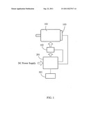
[0007] FIG. 1 is a schematic view showing the circuit block of the DC brushless motor drive circuit with current variable-voltage, according to the present invention.
DESCRIPTION OF MAIN COMPONENT SYMBOLS
[0008] (101): DC brushless motor [0009] (102): Motor load current detection device [0010] (103): Motor electric machinery angle position detection device [0011] (201): Motor drive control device [0012] (301): Running operation device
DETAILED DESCRIPTION OF THE PREFERRED EMBODIMENTS
[0013] The DC brushless motor drive circuit with current variable-voltage of the present invention relates to a drive circuit of the DC brushless motor driven by DC electric power and equipped with the electric machinery angle position detection device, in which the DC brushless motor is under various rotational speeds statuses produced on the basis of the magnitude of the input voltage and the load, through the load current detection device detecting the variation of the current, and the voltage input into the DC brushless motor is relatively increased or decreased according to the internal setting of the motor drive control device; especially, during the running at the range of high rotational speed, through the increased current value detected by the load current detection device to further increase the input voltage of the DC brushless motor according to the setting of the motor drive control device, thereby to overcome the increased inductive impedance of the magnetic field winding resulting from the increased rotational speed of the DC brushless motor by inputting larger current for providing the current of the DC brushless motor to produce required torque.
[0014] FIG. 1 is a schematic view showing the circuit block of the DC brushless motor drive circuit with current variable-voltage, according to the present invention, the main components including: [0015] DC brushless motor (101): constituted by the first electric machinery structure composed of the magnetic field winding and the magnetic circuit, and the second electric machinery structure composed of the permanent magnetic pole or the winding excitation type magnetic pole, in which the first electric machinery structure and the second electric machinery structure are driven by the relative revolution through the electric machinery effect between the both, the DC brushless electric machinery is installed with the motor electric machinery angle position detection device (103) for detecting the winding of the first electric machinery structure and the magnetic pole of the second electric machinery structure, and the detected signal is transmitted to the motor drive control device (201) for being the reference of controlling the operation of DC brushless motor (101); [0016] motor load current detection device (102): constituted by the current detection device composed of electromagnetic sensing method or impedance method, for detecting the value of the load current transmitted from the motor drive control device (201) to the DC brushless motor (101); [0017] motor electric machinery angle position detection device (103): constituted by the Hall element with magnetoelectric effect, or electric machinery angle position detection device with photoelectric effect or electromagnetic induction effect, or electromechanical electric machinery angle position detection device, to be installed at the DC brushless motor (101), for being placed between the first electric machinery structure equipped with magnetic field winding and the second electric machinery structure equipped with permanent magnetic pole or winding excitation type magnetic pole, to detect the electric machinery angle position between the magnetic field winding and the permanent magnetic pole or the winding excitation type magnetic pole placed at another electric machinery structure with relative coaxial revolution, in which the signal is transmitted to the motor drive control device (201), for being the reference of controlling the operation of DC brushless motor (101); [0018] motor drive control device (201): constituted by the electromechanical circuit device, and/or the solid state electronic device, and/or the microprocessor and related software, which is a circuit device performing linear or chopper type voltage regulation on DC electric energy; in which, the motor drive control device (201) is arranged for inputting DC power, being controlled by the running operation device (301), and receiving the signals from the motor electric machinery angle position detection device (103) and the motor load current detection device (102), for referring the feedback gain setting of the internal setting of the motor drive control device (201), to implement the control over the excitation phase sequence of magnetic field winding of the DC brushless motor (101), the ON/OFF control, and the control over the excitation voltage, the excitation current, the direction of the excitation current, and the excitation timing through the linear control method or the pulse width modulation method; and [0019] running operation device (301): constituted by the operation device including electromechanical or electronic switch, button, adjustable potentiometer, keyboard, and indicator, or constituted by the interface receiving the electric power signal, for controlling the motor drive control device (201), and further controlling the DC brushless motor (101).
[0020] For the DC brushless motor drive circuit with current variable-voltage, the motor drive control device (201) and the running operation device (301) can be integrated.
[0021] For the DC brushless motor drive circuit with current variable-voltage, the motor drive control device (201) and the running operation device (301) can be individually constituted.
[0022] For the DC brushless motor drive circuit with current variable-voltage of the present invention, in which, under various running speeds statuses, the voltage supplied to the DC brushless motor is relatively increased or decreased on the basis of the internal setting of the motor drive control device according to the increased or decreased load current, so as to prevent the shortcoming of too much change of the input impedance caused by the inductive reactance of the winding accordingly changed when the speed of the DC brushless motor is changed, specifically, to prevent the shortcoming that the inductive reactance is increased because of the increased rotational speed, thus, if the original running voltage is input, the current value is too low, and the required torque does not be produced.
User Contributions:
Comment about this patent or add new information about this topic:
Images included with this patent application:
 |
| Similar patent applications: | |
| Date | Title |
|---|---|
| 2011-09-22 | Dc brushless motor drive circuit with speed variable-voltage |
| 2011-09-29 | Pm brushless motor drive circuit topology and control |
| 2012-02-09 | Brushless motor drive circuit and brushless motor drive system |
| 2011-06-30 | Motor drive circuit for rotating a rotor by supplying the currents to two coils |
| 2012-01-19 | Brushless three phase motor drive control based on a delta zero crossing error |
| New patent applications in this class: | |
| Date | Title |
|---|---|
| 2016-12-29 | Power conversion control apparatus |
| 2016-06-09 | Solar energy utilization system |
| 2016-06-02 | Driving apparatus for an electric motor, a method for actuation thereof and a motor unit which comprises the driving apparatus |
| 2016-06-02 | Electric drive having an actively controlled dc bus |
| 2016-05-19 | Motor controller having a power-saving control, and a motor control system including the motor controller |
| Top Inventors for class "Electricity: motive power systems" | |
| Rank | Inventor's name |
|---|---|
| 1 | Steven E. Schulz |
| 2 | Silva Hiti |
| 3 | Yasusuke Iwashita |
| 4 | Brian A. Welchko |
| 5 | Kesatoshi Takeuchi |