Patent application title: AC POWER SUPPLY MEASURING CIRCUIT WITH VOLTAGE PROTECTING FUNCTION
Inventors:
Heng-Chen Kuo (Tu-Cheng, TW)
Heng-Chen Kuo (Tu-Cheng, TW)
Assignees:
HON HAI PRECISION INDUSTRY CO., LTD.
IPC8 Class: AG01R3142FI
USPC Class:
32476401
Class name: Fault detecting in electric circuits and of electric components of individual circuit component or element power supply
Publication date: 2011-09-15
Patent application number: 20110221467
Abstract:
An alternating current (AC) power supply measuring circuit includes a
voltage dividing circuit, a measuring integrated circuit (IC), a control
board, and a first power rectifying circuit. The voltage dividing circuit
receives an AC voltage signal and divides the AC voltage signal to a
first voltage dividing signal and a second voltage dividing signal. The
measuring IC receives the first and second voltage dividing signals to
obtain an AC voltage measuring signal. The control board receives the AC
voltage measuring signal and processes the AC voltage measuring signal.
The first power rectifying circuit provides a floating ground signal to
the voltage dividing circuit.Claims:
1. An alternating current (AC) power supply measuring circuit comprising:
a first input terminal and a second input terminal, to receive an
external AC voltage signal; a voltage dividing circuit to receive the AC
voltage signal and divide the AC voltage signal to a first voltage
dividing signal and a second voltage dividing signal, the voltage
dividing circuit comprising first to fourth resistors connected between
the first and second input terminals in series; a first dividing node
between the first and second resistors outputting the first voltage
dividing signal, a second dividing node between the third and fourth
resistors outputting the second voltage dividing signal; a measuring
integrated circuit (IC) to receive the first and second voltage dividing
signals to obtain an AC voltage measuring signal; a control board to
receive the AC voltage measuring signal and process the AC voltage
measuring signal; and a first power rectifying circuit to provide a
floating ground signal to the voltage dividing circuit, a ground node
between the second and third resistors receiving the floating ground
signal.
2. The measuring circuit of claim 1, further comprising a second power rectifying circuit, the first power rectifying circuit rectifying the AC voltage signal to a first direct current (DC) voltage signal to the measuring IC, the second power rectifying circuit rectifying the AC voltage signal to a second DC voltage signal to the control board.
3. The measuring circuit of claim 1, further comprising a photo coupling circuit, wherein the measuring IC transfers the AC voltage measuring signal to a micro control unit of the control board through the photo coupling circuit.
4. The measuring circuit of claim 1, wherein a ratio of impedance between the first resistor and the second resistor is equal to a ratio of impedance between the fourth resistor and the third resistor.
Description:
BACKGROUND
[0001] 1. Technical Field
[0002] The present disclosure relates to measuring circuits, and particularly, to an alternating current (AC) power supply measuring circuit with voltage protecting function.
[0003] 2. Description of Related Art
[0004] Conventional power supplies for electronic equipments employ three-wire AC configuration. Generally, a "hot pin" and a "neutral pin" provide electrical power, and a "ground pin" for shorting dangerous current to ground.
[0005] AC wall outlets are sometimes miswired. The hot wire may be connected to the neutral pin and the neutral wire connected to the hot pin or the neutral wire may be connected to the grounding pin and the grounding wire connected to the neutral pin or variations of these misconnections. These miswiring may present an electrocution or shock hazard or may damage equipment connected to the miswired electrical outlet.
BRIEF DESCRIPTION OF THE DRAWINGS
[0006] Many aspects of the embodiments can be better understood with reference to the following drawings. The components in the drawings are not necessarily drawn to scale, the emphasis instead being placed upon clearly illustrating the principles of the present embodiments. Moreover, in the drawings, like reference numerals designate corresponding parts throughout the several views.
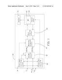
[0007] FIG. 1 is a block diagram of an embodiment of an alternating current (AC) power supply measuring circuit including a voltage dividing circuit.
[0008] FIG. 2 is a circuit diagram of the voltage dividing circuit of FIG. 1.
DETAILED DESCRIPTION
[0009] Referring to FIG. 1, an embodiment of an alternating current (AC) power supply measuring circuit 100 includes a first power rectifying circuit 10, a second power rectifying circuit 20, a voltage dividing circuit 30, a measuring integrated circuit (IC) 40, a photo coupling circuit 50, a control board 60, and a display 70. The control board 60 includes a micro control unit (MCU) 62. For receiving an external AC power supply, the measuring circuit 100 further includes a first input terminal L1 and a second input terminal N/L2. For protecting users from getting an electric shock, an enclosure ground terminal EG is also provided, and electronically connects to a metal enclosure of the measuring circuit 100. The first input terminal L1, the second input terminal N/L2, and the enclosure ground terminal EG are typically assembled in an electrical plug (not shown).
[0010] When the electrical plug of the measuring circuit 100 is plugged into an AC wall outlet (not shown) which is a 110 volt (V) or a 220V single-phase two-wire-plus-ground (1Φ2W+G) system, the first input terminal L1 electrically connects to a hot pin of the electrical outlet, the second input terminal N/L2 electrically connects to a neutral pin of the electrical outlet, and the ground terminal EG electrically connects to a ground pin of the electrical outlet. When the electrical plug of the measuring circuit 100 is plugged into an AC wall outlet (not shown) which is a 220V single-phase three-wire electrical (1Φ3W) system, the first input terminal L1 electrically connects to a first hot pin of the electrical outlet, the second input terminal N/L2 electrically connects to a second hot pin of the electrical outlet, and the ground terminal EG electrically connects to a ground pin of the electrical outlet.
[0011] The first power rectifying circuit 10 connects to the first input terminal L1 and the second input terminal N/L2, to receive an AC voltage signal from the first input terminal L1 and the second input terminal N/L2, and rectify the AC voltage signal to a first direct current (DC) voltage signal to the measuring IC 40. Furthermore, the first power rectifying circuit 10 provides a floating ground signal FG, such as 0V voltage signal, to the voltage dividing circuit 30.
[0012] The second power rectifying circuit 20 connects to the first input terminal L1 and the second input terminal N/L2, to receive the AC voltage signal from the first input terminal L1 and the second input terminal N/L2, and rectify the AC voltage signal to a second direct current (DC) voltage signal to the control board 60.
[0013] Referring to FIG. 2, the voltage dividing circuit 30 includes four resistors R1-R4 connected between the first input terminal L1 and the second input terminal N/L2 in series. A ground node between the resistors R2 and R3 connects to the first power rectifying circuit 10 to receive the floating ground signal FG. A dividing node between the resistor R1 and the resistor R2 is used to output a first voltage dividing signal Vsense+, which is determined by the AC voltage signal from the first input terminal L1 and the resistances of the resistors R1 and R2. A dividing node between the resistor R3 and the resistor R4 is used to output a second voltage dividing signal Vsense-, which is determined by the AC voltage signal from the second input terminal N/L2 and the resistances of the resistors R3 and R4. In one embodiment, a ratio of impedance between the resistor R1 and the resistor R2 is equal to a ratio of impedance between the resistor R4 and the resistor R3.
[0014] The voltage dividing circuit 30 includes two dividing nodes to output the first and second voltage dividing signal Vsense+ and Vsense- respectively, and receives a floating ground signal FG between the resistors R2 and R3, therefore, the first input terminal L1 and the second input terminal N/L2 can be coupled with either the 110V or 220V single-phase two-wire-plus-ground (1Φ2W+G) systems, or the 220V single-phase three-wire electrical (1Φ3W) system. Even if swapping of the neutral pin with the hot pin of the AC wall outlet occurs, electrocution hazard for individuals and the measuring IC 40 is prevented.
[0015] The measuring IC 40 receives the first and second voltage dividing signals Vsense+ and Vsense- to obtain an AC voltage measuring signal. The measuring IC 40 transfers the AC voltage measuring signal to the MCU 62 through the photo coupling circuit 50. The MCU 62 processes the data of the AC voltage measuring signal and displays a measuring result on the display 70.
[0016] Furthermore, the measuring IC 40 and the control board 60 are powered by two individual power rectifying circuits 10 and 20, and electrically divided by the photo coupling circuit 50, which can effectively prevent electrical noise passing between the measuring IC 40 and the control board 60 and can increase measuring precision.
[0017] It is to be understood, however, that even though numerous characteristics and advantages of the embodiments have been set forth in the foregoing description, together with details of the structure and function of the embodiments, the disclosure is illustrative only, and changes may be made in details, especially in matters of shape, size, and arrangement of parts within the principles of the embodiments to the full extent indicated by the broad general meaning of the terms in which the appended claims are expressed.
User Contributions:
Comment about this patent or add new information about this topic:
| People who visited this patent also read: | |
| Patent application number | Title |
|---|---|
| 20140375084 | MOTOR VEHICLE ARRANGEMENT HAVING A THREE-ELEMENT WATER BOX |
| 20140375080 | CARGO BED STAKE POCKET ADAPTED FOR SECURING J-HOOK STRAP THERETO |
| 20140375078 | VEHICLE SIDE DOOR STRUCTURE |
| 20140375077 | Tonneau Cover Having a Draw Cord |
| 20140375072 | GRIPPER DEVICE HAVING HOLDING POINTS |
Images included with this patent application:
 |  |
| New patent applications in this class: | |
| Date | Title |
|---|---|
| 2019-05-16 | Improvements in or relating to the detection of a fault on a power converter |
| 2018-01-25 | Universal power distribution test tool and methodology |
| 2017-08-17 | Detecting a failure of a phase in a grid for inverters having a frequency detection in an intermediate dc voltage link |
| 2016-12-29 | Abnormality detecting circuit and abnormality detecting method |
| 2016-12-29 | Methods and apparatus for monitoring a level of a regulated source |
| New patent applications from these inventors: | |
| Date | Title |
|---|---|
| 2011-12-08 | Relay drive circuit |
| 2011-12-08 | Voltage protecting circuit for electronic device |
| 2011-12-01 | Server enclosure and connection element thereof |
| 2011-12-01 | Over-voltage protection device |
| 2011-11-10 | Power device |
| Top Inventors for class "Electricity: measuring and testing" | |
| Rank | Inventor's name |
|---|---|
| 1 | Udo Ausserlechner |
| 2 | David Grodzki |
| 3 | Stephan Biber |
| 4 | William P. Taylor |
| 5 | Markus Vester |