Patent application title: PLUNGER
Inventors:
William John Keegan (San Jose, CA, US)
IPC8 Class: AE03D1100FI
USPC Class:
425512
Class name: Obstruction remover force cup (e.g., a plunger) with one way valve
Publication date: 2011-09-15
Patent application number: 20110219526
Abstract:
A plunger can include a head configured to engage an opening to a
conduit. The plunger can also include a one-way valve that allows fluid
flow through the head and out of the plunger, but that inhibits fluid
flow through the head and into the plunger. The plunger can also include
a pressurizing mechanism that forces fluid to flow through the head and
out of the plunger. The mechanism can be detachable from the head. A head
of a plunger can be positioned to engage an opening of an obstructed
conduit. A force can be applied to the plunger, and the plunger can
increase a fluid pressure within the conduit in response to the force.
The force on the plunger can be released, and the plunger can maintain
the fluid pressure within the conduit at an increased level after the
force is released.Claims:
1. A plunger comprising: a head configured to engage an opening to a
conduit; a one-way valve that allows fluid flow through the head and out
of the plunger in a first direction, but that inhibits fluid flow through
the head and into the plunger in a second direction that is opposed to
the first direction; and a pressurizing mechanism that forces fluid to
flow through the head in the first direction.
2. The plunger of claim 1, wherein the mechanism comprises a bellows.
3. The plunger of claim 2, further comprising a handle between the bellows and the head.
4. The plunger of claim 1, wherein the head is tapered.
5. The plunger of claim 1, wherein the head is not tapered.
6. The plunger of claim 1, further comprising a screen positioned on an opposite side of the one-way valve from the mechanism.
7. The plunger of claim 1, wherein the head comprises a material selected from a group consisting of elastomeric material, rubber material, and combinations thereof.
8. The plunger of claim 1, wherein the mechanism comprises a bellows, the bellows comprising a first end with an intake and a second end with an exit, the exit of the bellows being in fluid communication with the head.
9. The plunger of claim 8, further comprising a handle between the exit of the bellows and the head.
10. The plunger of claim 9, wherein the handle comprises a pipe that extends from the exit of the bellows and the head.
11. The plunger of claim 8, wherein the one-way valve is positioned between the exit of the bellows and an exit of the head.
12. A method of operating a plunger comprising: positioning a head of the plunger to engage an opening of an obstructed conduit; applying a force to the plunger, the plunger increasing a fluid pressure within the conduit in response to the force; releasing the force on the plunger, the plunger maintaining the fluid pressure within the conduit at an increased level after the force is released.
13. The method of claim 12, wherein the force is a first force, and wherein the method further comprises applying a second force to the plunger while the plunger maintains the fluid pressure within the conduit at the increased level, the plunger further increasing the fluid pressure within the conduit in response to the second force.
14. The method of claim 12, further comprising securing a pressurized fluid supply line to the plunger and supplying pressurized fluid from the fluid supply line through the head of the plunger.
15. The method of claim 12, wherein the head is a first head and the method further comprises replacing the first plunger head with a second plunger head on the plunger, the second head being a different shape than the first head.
16. The method of claim 15, wherein the force is a first force and the method further comprises: positioning the second head of the plunger to engage an opening of a second obstructed conduit; applying a second force to the plunger, the plunger increasing a fluid pressure within the second conduit in response to the second force; releasing the second force on the plunger, the plunger maintaining the fluid pressure within the second conduit at an increased level after the second force is released.
17. A plunger comprising: a head that is configured to engage an opening of a conduit; and a mechanism that is configured to supply fluid to the head and force the fluid through the head and into the conduit, the mechanism being detachable from the head.
18. The plunger of claim 17, wherein the mechanism comprises a fluid chamber.
19. The plunger of claim 17, wherein the mechanism comprises a bellows.
20. The plunger of claim 17, wherein the mechanism comprises a pressurized fluid supply line.
21. The plunger of claim 17, further comprising a one-way valve that allows fluid flow through the head and out of the plunger in a first direction, but that inhibits fluid flow through the head and into the plunger in a second direction that is opposed to the first direction.
22. A plunger kit comprising: a pressurizing mechanism; a first head configured to be attached in communication with the pressurizing mechanism, such that fluid is allowed to flow from the pressurizing mechanism through the first head in a first direction but fluid is inhibited from flowing from the first head to pressurizing mechanism in a second direction; and a second head that is configured to be attached in communication with the pressurizing mechanism, such that fluid is allowed to flow from the pressurizing mechanism through the second head in the first direction but fluid is inhibited from flowing from the second head to the pressurizing mechanism in a second direction.
23. The plunger kit of claim 22, wherein the pressurizing mechanism provides pressurized fluid in response to a force being applied to the mechanism.
24. The plunger kit of claim 22, wherein the pressurizing mechanism comprises a bellows.
25. The plunger kit of claim 22, wherein the kit comprises at least one one-way valve.
26. The plunger kit of claim 22, wherein the first head is shaped differently than the second head.
27. The plunger kit of claim 22, wherein the first head is a different size from the second head.
Description:
BACKGROUND
[0001] Plungers are often used to unclog conduits, such as drains and drainpipes for toilets, sinks, tubs, and showers. A standard plunger includes a head that includes a chamber that can be positioned in a drain, with the chamber opening into the drain. A plunger typically also includes a handle attached to the head. The handle can be pushed down make the chamber smaller and push liquid into the drain, and/or pulled up to make the chamber larger and pull liquid up from the drain. This can increase the pressure in the drain (by pushing down) and/or decrease pressure in the drain (by pulling up), which may dislodge obstructions within the drain or attached drainpipes.
SUMMARY
[0002] While standard plungers may unclog many clogged conduits, the present inventor has recognized drawbacks with standard plungers. For example, the inventor has found that with many standard plungers, the pushing and pulling action described above can merely push and pull the clog in and out of the same area in a clogged drainpipe, without dislodging the clog. The inventor has invented improved plunger features described herein, which may be used alone or in combination.
[0003] According to one embodiment, a plunger can include a head configured to engage an opening to a conduit. The plunger can also include a one-way valve that allows fluid (i.e., liquid and/or gas such as air) to flow through the head and out of the plunger in a first direction, but that inhibits fluid from flowing through the head and into the plunger in a second direction that is opposed to the first direction. The plunger can also include a pressurizing mechanism that forces fluid to flow through the head in the first direction.
[0004] According to another embodiment, a technique for operating a plunger can include positioning a head of the plunger to engage an opening of an obstructed conduit. The technique can also include applying a force to the plunger, and the plunger can increase a fluid pressure within the conduit in response to the force. The force on the plunger can be released, and the plunger can maintain the fluid pressure within the conduit at an increased level after the force is released (if the clog has not already cleared).
[0005] According to yet another embodiment, a plunger can include a head that is configured to engage an opening of a conduit. The plunger can also include a mechanism that is configured to supply fluid to the head and force the fluid through the head and into the conduit. The mechanism can be detachable from the head.
[0006] According to yet another embodiment, a plunger kit can include a pressurizing mechanism, a first head, and a second head. The first head can be configured to be attached in communication with the pressurizing mechanism, such that fluid is allowed to flow from the pressurizing mechanism through the first head in a first direction but fluid is inhibited from flowing from the first head to pressurizing mechanism in a second direction. Moreover, the second head can be configured to be attached in communication with the pressurizing mechanism, such that fluid is allowed to flow from the pressurizing mechanism through the second head in the first direction but fluid is inhibited from flowing from the second head to the pressurizing mechanism in a second direction.
[0007] This Summary is provided to introduce a selection of concepts in a simplified form. The concepts are further described below in the Detailed Description. This Summary is not intended to identify key features or essential features of the claimed subject matter, nor is it intended to be used to limit the scope of the claimed subject matter. Similarly, the invention is not limited to implementations that address the particular techniques, tools, environments, disadvantages, or advantages discussed in the Background, the Detailed Description, or the attached drawings.
BRIEF DESCRIPTION OF THE DRAWINGS
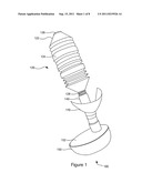
[0008] FIG. 1 is a perspective view of a plunger.
[0009] FIG. 2 is a side plan view of another plunger with a head positioned to seal with a drain.
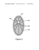
[0010] FIG. 3 is a sectional view taken along line 3-3 of FIG. 2, but not showing the drain structure of FIG. 2.
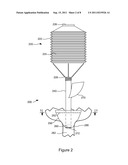
[0011] FIG. 4 is a side plan view of another plunger with a head positioned to seal with a drain.
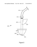
[0012] FIG. 5 is a side plan view of the plunger of FIG. 2 attached to a pressurized fluid supply line instead of a bellows.
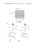
[0013] FIG. 6 is a side plan view of a plunger kit.
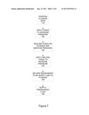
[0014] FIG. 7 is a flowchart of a technique for operating a plunger.
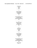
[0015] FIG. 8 is a flowchart of another technique for operating a plunger.
[0016] The description and drawings may refer to the same or similar features in different drawings with the same reference numbers.
DETAILED DESCRIPTION
[0017] Referring to FIG. 1, a plunger (100) can include a pressurizing mechanism (120), which can include a bellows (122) having a body (124), an air intake (126) at the top of the body (124), and an air exit (128) at the bottom of the body (124). The bellows (122) can be compressed to force air out of the body (124) or stretched to draw air into the body (124). For example, the bellows (122) may be a bellows that is similar to bellows used as heads for some current bellows plungers. For example, the bellows (122) may be formed of a flexible rubber or plastic material.
[0018] A handle (140) can extend down from the air exit (128) of the bellows (122). The handle (140) can be secured to the bellows (122) in any of various ways. For example, the handle (140) may include female threads that engage male threads on the air exit (128) of the bellows (122). The handle (140) can be a standard pipe, such as a pipe formed of polyvinyl chloride (PVC) or some other piping material. The handle (140) can also extend through a head (150), which can be configured to seal with standard drains, such as sink, toilet, tub, and/or shower drains. For example, the head (150) may taper as it extends away from the bellows (122). As an example, the head may form a generally oblong frustro-conical shape that is sized to extend into a drain with the tapering portion of the head (150) engaging edges of the drain to form the seal with the drain (see FIG. 2; see also FIGS. 1 and 3 showing the oblong shape). The head (150) can be formed of a flexible material that will conform to and form a seal with a drain. For example, the head (150) can be formed of a soft rubber-like material that is waterproof, such as a rubber and/or elastomeric material.
[0019] The head (150) may be secured to the handle (140) in one or more of various ways. For example, the head (150) may be adhered to the handle (140). In addition, the plunger (100) may include a head support (152) to inhibit upward sliding of the head (150) along the handle (140). For example, the handle (140) may include a sleeve, and the head support (152) may be a circular flange or hollowed disk positioned just below the sleeve, so that the head support (152) can keep the head (150) from sliding upward, and the sleeve can keep the head support (152) from sliding upward. The head support (152) may be formed of any of various rigid materials, such as wood, metal, rigid polymers, etc.
[0020] The plunger (100) can also include a one-way valve (not shown) positioned within the head, so that fluid passing through the handle (140) will also pass through the one-way valve. The one-way valve can be oriented so that it will allow fluid to pass downward and out of the plunger (100) through the head (150), but it will inhibit fluids from passing back up through the head (150). The plunger (100) can also include a screen (not shown) below the one-way valve to prevent unwanted debris from entering the one-way valve or the remainder of the plunger.
[0021] In addition, the plunger (100) can include a shield (170), which can be positioned to shield a user's hand from liquid or solid matter that may splash up from the drain. The shield (170) may be formed of a rigid polymer material, or other sufficiently rigid material. The shield (170) can be attached to the handle (140) in any of various ways, such as by an adhesive or by being formed integrally with the handle (140).
[0022] In use, a user can place one hand on the handle (140) above the shield (170) and position the head (150) in a sealing position with a clogged drain (see FIG. 2). The user's other hand can be used to cover the air intake (126) and to apply force to the top of the bellows (122). That force can compress the body (124) of the bellows (122), forcing air (or possibly some other fluid contained in the bellows) through the handle (140), through the one-way valve, and into the drain, thereby increasing pressure within the drain. This increased pressure may be sufficient to force debris within the drain or drainpipe to move through the drainpipe, thereby unclogging the drain. If not, the user can keep the head in place and repeat the technique. Specifically, the user can uncover the air intake to allow air to pass into the bellows body (124) as the bellows (122) stretches to its original uncompressed shape. While this happens, the one-way valve can inhibit air or other fluid from passing out of the drain or drainpipe and back into the plunger (100), as typically occurs when using standard bellows plungers. Accordingly, the plunger (100) can maintain the increased pressure within the drain (although this maintaining does not preclude the possibility of some pressure being lost due to some fluid leaking out, such as fluid leaking through the plunger-drain seal, one-way valve, and/or the clog in the drain or drainpipe). The user can again cover the air intake (126) and compress the bellows (122) to increase pressure within the drain even more. If necessary, the user can uncover the air intake (126) to allow the bellows to return to its original position, cover the air intake (126) again, and compress the bellows (122) again. This technique can be repeated to keep increasing pressure until the pressure is sufficient to dislodge the clog in the drain.
[0023] Accordingly, this arrangement and technique can produce substantial benefits that are not present in or predictable from prior plungers. For example, the plunger (100) can increase pressure within a clogged drain line more with each compression of the bellows (122), rather than losing the pressure from previous compressions when preparing for another compression. However, the subject matter defined in the appended claims is not necessarily limited to this or other benefits described herein. A particular implementation of the invention may provide all, some, or none of the benefits described herein.
[0024] Referring now to FIG. 2, an alternative plunger (200) will be discussed. The plunger (200) can include a pressurizing mechanism (220). The pressurizing mechanism (220) can include a bellows (222) with a body (224), air intake (226), and air exit (228), similar to the bellows (122) discussed above with reference to FIG. 1. However, the bellows (222) may be broader and shorter than the bellows (122) of FIG. 1. Indeed, the bellows (222) for the plunger (200) may be any of various shapes and designs, so long as the bellows (222) is configured to force air down through the air exit (228). A handle (240) can be a pipe, as discussed above with reference to FIG. 1. The handle (240) can include male threads that engage female threads in the air exit (228) to secure the handle (240) to the bellows (122). The handle (240) can extend down and through a head (250), which can be shaped in a similar way and comprised of similar materials to the head (150) discussed above with reference to FIG. 1.
[0025] The plunger (200) can also include a head support (252), which can be formed as an integral part with the handle (240). Accordingly, the head support (252) can be formed of the same material as the handle (240), which may be PVC or similar material. The head support (252) can be enclosed within the head (250). For example, the head (250) may be molded around the head support (252). The head support (252) can include spokes (254) and a rim (256), with the spokes extending radially out from the handle (240) to the rim (256), as is illustrated in FIG. 3. The head support (252) may include different numbers of spokes (ten are illustrated in FIG. 3, but four, six, eight, or some other number may be used) and/or be in some other configuration. Indeed, the head support (252) could take any of various other shapes, and be in various other positions, so long as it inhibits upward movement of the head (250) along the handle (240).
[0026] Referring still to FIG. 2, the plunger (200) can include a one-way valve (260) within the head (250), although the one-way valve (260) could be positioned elsewhere, such as at the air exit (228) of the bellows (222). The one-way valve (260) can be oriented to allow fluid to flow downward through the handle (240) and out of the plunger (200), but to inhibit fluid flow back up through the one-way valve (260) and the handle (240).
[0027] The plunger (200) can also include a shield (270), which can be formed as an integral part with the handle (240) and the head support (252). Accordingly, the shield (270) can be made of the same material as the handle (240) and the head support (252), such as PVC or similar material.
[0028] In addition, the plunger (200) can include a screen (272) located downstream of the one-way valve (260). The screen (272) can prevent solid debris from entering the plunger (200), and possibly interfering with the operation of the one-way valve (260) or other parts of the plunger (200).
[0029] As illustrated in FIG. 2, the head (250) of the plunger (200) can be positioned so that the tapering portion of the head (250) engages a drain (280), such as a toilet drain or trap, a sink drain, a shower or tub drain, etc. The plunger (200) may also be used for unclogging other types of conduits, such as fluid lines in industrial applications, etc. The drain (280) can be connected to a drainpipe (282), which can be any of various different types of conduits (PVC pipes, steel pipes, etc.).
[0030] The plunger (200) can be operated in the same way as the plunger (100) discussed above.
[0031] Referring now to FIG. 4, another plunger (400) will be discussed. The plunger (400) is similar to the plunger (200) discussed above, having a similar pressuring mechanism (420) that includes a bellows (422), body (424), air intake (426), and air exit (428), as well as a similar handle (440). The plunger (400) can have a head (450) that is a different shape from the head (250) of the plunger (200). Specifically, the head (450) can have sides that extend straight down, rather than tapering as in the head (250) discussed above. For example, the head (450) may be a generally cylindrical shape. The head (450) may also be a different size from the head (250). For example, the head (250) discussed above may taper from a top diameter of 6 inches to a bottom diameter of 3.5 inches, while the head (450) may have a constant diameter of 4.25 inches. The plunger (400) may also include a head support (452), one-way valve (460), shield (470), and screen (472) similar to the plunger (200) of FIG. 2.
[0032] The head (450) may be useful for a smaller drain (480) that leads to a drainpipe (482). For example, the head (250) may not fit within the drain (480), but the head (450) can be pressed down to engage an area around the drain (480) and form a seal, as illustrated in FIG. 4. With the head (450) so positioned, the plunger (400) can operate similar to the plungers (100 and 200) discussed above.
[0033] Referring now to FIG. 5, the bellows (222) of the plunger (200) discussed above with reference to FIG. 2 can be twisted off, and a pressurized fluid supply line (510) (such as a garden hose) can be secured to the top of the handle (240) by twisting a threaded end fitting (512) on the pressurized fluid supply line (510) onto the threads at the top of the handle (240). For example, the pressurized fluid supply line (510) may be a standard garden hose that is connected to a supply of pressurized water. The head (250) of the plunger (200) can be held in engagement with a drain, as illustrated in FIG. 2. Pressurized fluid (such as water) can then be supplied through the pressurized fluid supply line (510), through the handle (240), and into the drain and the drainpipe to increase the pressure within the drain and drainpipe and dislodge a clog within the drain or drainpipe.
[0034] Referring now to FIG. 6, a plunger kit (600) according to the present invention may include a single pressurizing mechanism, such as the pressurizing mechanism (220) discussed above. The kit may also include the remainder of the components of the plunger (200) discussed above, and the components of the plunger (400) (other than the pressurizing mechanism (420)). The pressurizing mechanism (220) can be configured to be secured to and supply pressure to the components of either plunger (200 or 400), as discussed above, depending upon which head (250 or 450) is desired for a particular obstructed conduit. Also, the components of either plunger (200 or 400) can be configured to be used with a pressurized fluid supply line, as discussed above with reference to FIG. 5. Accordingly, the components of the kit (600) can be mixed and matched as desired for unclogging a particular obstructed conduit.
[0035] Techniques for operating a plunger will now be discussed. Although operations for the various techniques are described herein in a particular, sequential order for the sake of presentation, it should be understood that this manner of description encompasses rearrangements in the order of operations, unless a particular ordering is required. For example, operations described sequentially may in some cases be rearranged or performed concurrently. Techniques described herein with reference to flowcharts may be used with one or more of the systems described herein and/or with one or more other systems. Moreover, for the sake of simplicity, flowcharts may not show the various ways in which particular techniques can be used in conjunction with other techniques.
[0036] A technique for operating a plunger will now be discussed with reference to FIG. 7. In the technique, a head of a plunger can be positioned (710) to engage an opening of an obstructed conduit. A force can be applied (720) to the plunger, and the plunger can increase a fluid pressure within the conduit in response to the force. The force on the plunger can be released (730), but the plunger can maintain the fluid pressure within the conduit at an increased level after the force is released. Of course, in some situations the pressure may not be maintained after releasing (730) the force because the clog may have already become dislodged, thereby releasing the pressure within the conduit. The technique may also include applying (740) a second force to the plunger while the plunger maintains the fluid pressure within the conduit at the increased level. However, there may be some drop in pressure due to leakage of fluid from the conduit, as discussed above. The plunger can further increasing the fluid pressure within the conduit in response to the second force. The technique may also include securing (750) a pressurized fluid supply line to the plunger, and supplying (760) pressurized fluid from the fluid supply line through the head of the plunger.
[0037] Another technique for operating a plunger will now be discussed with reference to FIG. 8. In the technique, a first plunger head can be positioned (810) to engage an opening of an obstructed conduit. A force can be applied (820) to the plunger, and the plunger can increase a fluid pressure within the conduit in response to the force. The force on the plunger can be released (830), but the plunger can maintain the fluid pressure within the conduit at an increased level after the force is released. The technique can also include replacing (840) the first plunger head with a second plunger head on the plunger, the second head being a different shape than the first head. Additionally, the second plunger head can be positioned (850) to engage an opening of a second obstructed conduit. A second force can be applied (860) to the plunger, and the plunger can increase a fluid pressure within the second conduit in response to the second force. The second force on the plunger can be released (870), and the plunger can maintain the fluid pressure within the second conduit at an increased level after the second force is released.
[0038] While the invention has been particularly shown and described with reference to preferred embodiments thereof, it will be understood by those skilled in the art that various changes in form and details may be made therein without departing from the spirit and scope of the invention. For example, the bellows may be replaced with some other type of pressurizing mechanism, such as a piston mechanism.
User Contributions:
Comment about this patent or add new information about this topic:
Images included with this patent application:
 |  |
 |  |
 |  |
 |  |
| Top Inventors for class "Baths, closets, sinks, and spittoons" | |
| Rank | Inventor's name |
|---|---|
| 1 | William T. Ball |
| 2 | Joseph R. Cook |
| 3 | David Grover |
| 4 | Ralph Butter-Jentsch |
| 5 | Kun Yuan Tong |