Patent application title: VISUAL IMAGE SCORING
Inventors:
Erik Anderson (Fairfax, VA, US)
IPC8 Class: AA63F924FI
USPC Class:
463 2
Class name: Amusement devices: games including means for processing electronic data (e.g., computer/video game, etc.) in a game including a simulated projectile (e.g., bullet, missile, ball, puck, etc.)
Publication date: 2011-09-08
Patent application number: 20110218021
Abstract:
An image-based system and process of paper target scoring, and paper
targets for use therewith, are disclosed. The system and process utilize
functions that accumulate accuracy values based upon presumptions
supplied to the present invention based upon the characteristics of
bullet holes within paper target prior to any center point analysis.
Subpixel analysis of images may heighten the accuracy of the scoring. The
paper targets possess visual attributes adapted to permit scoring of the
paper targets to be more rapid, facile, accurate, and secure.Claims:
1. A process of measuring a high-velocity puncture in a substantially
planar object, said process comprising: disseminating planar target
sheets from a predefined set of stored template target sheet images
bearing a target with a space color and bull color, target sheet
information, and reference data; transmitting a captured image of at
least one target sheet bearing at least one high-velocity puncture to a
processor; calibrating said captured image of said punctured target sheet
by comparing said captured image to said reference data of a correlating
stored template target sheet image to produce correction data; extracting
from said punctured target sheet puncture edge data characterizing color
data related to said puncture and the periphery of at least two of said
punctures; calculating from said captured image a standard puncture
dimension based on the puncture edge data of at least two of said
punctures; and identifying a likely puncture center point for a reviewed
puncture from said captured image as a function of said correction data,
puncture edge data from said reviewed puncture, and a 2-D index of
puncture accumulation values from said standard puncture dimension
repeatedly overlayed according to said puncture edge data of said
reviewed puncture.
2. The process of claim 1 further comprising adjusting said likely puncture center point based on neighboring index values to produce an adjusted puncture center point.
3. The process of claim 2 further comprising extracting from said punctured target sheet bull edge data characterizing color data related to said bull and the periphery of at least two of said bulls.
4. The process of claim 3 further comprising calculating from said captured image a standard bull dimension based on the bull edge data of at least two of said bulls.
5. The process of claim 4 further comprising identifying a likely bull center point of a reviewed bull as a function of said correction data, bull edge data from said reviewed bull, and a 2-D index of bull accumulation values from said standard bull dimension repeatedly overlayed according to said bull edge data.
6. The process of claim 5 further comprising adjusting said likely bull center point based on neighboring bull index values to produce an adjusted bull center point.
7. The process of claim 6 further comprising determining a score value based on said modified puncture center point and said adjusted bull center point.
8. The process of claim 7 further comprising presenting a reliability score derived from said 2-D index of puncture accumulation.
9. The process of claim 3 further comprising depicting a map overlay comprising: said captured image of at least one target sheet bearing at least one high-velocity puncture; a graphical overlay, superimposed upon said captured image, bearing a positional depiction of said puncture edge data and said bull edge data.
10. The process of claim 1 wherein said disseminating step includes disseminating planar target sheets from said predefined set of stored template target sheet images bearing said target with a single space color and single bull color with a uniform fill complexion.
11. The process of claim 10 wherein said disseminating step includes disseminating planar target sheets from said predefined set of stored template target sheet images bearing said target with a circular bull.
12. The process of claim 11 wherein said disseminating step includes disseminating planar target sheets with reference data comprising at least one reference line and reference point.
13. The process of claim 12 wherein said disseminating step includes disseminating planar target sheets with reference data comprising at least two reference lines and reference point; and said transmitting step includes transmitting said captured image of at least one target sheet bearing at least one high-velocity puncture to a processor from a digital camera.
14. The process of claim 1 wherein said disseminating step includes disseminating planar target sheets with target sheet information comprising an individual target sheet identifier and a target sheet security code derived from the target sheet identifier.
15. A target sheet suited to rapid measurement of a high-velocity puncture, said target sheet comprising: a substantially planar target sheet body with a view surface; a uniformly-colored space on said view surface; a circular bull, within said space, uniformly filled with a single bull color; and reference data, on said body, comprising a reference line and a predefined reference point.
16. The target sheet of claim 15 further comprising a target scheme identifier, on said body, adapted to communicate to an electronic reader information that identifies position data of said bull and reference data.
17. The target sheet of claim 16 further comprising an individual identification number on said body.
18. The target sheet of claim 16 wherein said reference data includes at least two reference lines.
19. A system measuring a high-velocity puncture in a substantially planar object, said system comprising: an arithmetic logic unit (ALU); persistent storage, in signaled communication with said ALU, bearing a set of stored template target sheet images bearing a target with a space color and bull color, target sheet information, and reference data; a printer, in signaled communication with said ALU, adapted to print a substantially planar target sheet from said set of stored template target sheet images, said target sheet including: a uniformly-colored space on a view surface, a circular bull, within said space, with a uniformly filled single bull color; and reference data with a reference line and a predefined reference point; and an image scanning device, in signaled communication with said ALU, adapted to accept said target sheet.
20. The system of claim 19 further comprising: a transmitter function for transmitting a captured image of at least one target sheet bearing at least one high-velocity puncture to said ALU; a calibration function for calibrating said captured image of said punctured target sheet by comparing said captured image to said reference data of a correlating stored template target sheet image to produce correction data; an extraction function for extracting from said punctured target sheet puncture edge data characterizing color data related to said puncture and the periphery of at least two of said punctures; a calculator function for collecting from said captured image a standard puncture dimension based on the puncture edge data of at least two of said punctures; and an identification function for identifying a likely puncture center point for a reviewed puncture from said captured image as a function of said correction data, puncture edge data from said reviewed puncture, and a 2-D index of puncture accumulation values from said standard puncture dimension repeatedly overlayed according to said puncture edge data of said reviewed puncture.
21. The system of claim 20 further comprising an adjusting function for adjusting said likely puncture center point based on neighboring index values to produce an adjusted puncture center point.
22. The system of claim 21 further comprising: a bull extraction function for extracting from said punctured target sheet bull edge data characterizing color data related to said bull and the periphery of at least two of said bulls; a bull calculator function for collecting from said captured image a standard bull dimension based on the bull edge data of at least two of said bulls; a bull identification function for identifying a likely bull center point of a reviewed bull as a function of said correction data, bull edge data from said reviewed bull, and a 2-D index of bull accumulation values from said standard bull dimension repeatedly overlayed according to said bull edge data; and a bull adjustment function for adjusting said likely bull center point based on neighboring bull index values to produce an adjusted bull center point.
Description:
FIELD OF THE INVENTION
[0001] The present invention relates to the field of computer-aided measurement of apertures and more specifically to the field of measurement of projectile puncture dimensions in a target.
BACKGROUND
[0002] The history of the shooting sports dates at least as far back to the 15th century when, in an effort to better organize a town's defenses, townspeople would gather periodically to practice their crossbowmenship skills. The process of scoring, assigning a value to each shot fired, has changed little in the last 500 years. Each competitor shoots a series of projectiles at an aiming mark. The score of each shot is typically represented with a numeric value, with the highest numeric values assigned to the shots closest to the center of the aiming mark. Human evaluation of each shot against the center of the aiming mark is the most widely used method for scoring. Pre-printed paper targets, with each aiming mark overlaid with a series of concentric circles facilitates the scoring process. However the scoring process is still manual. Visual Image Scoring is an invention to automate the scoring process for paper targets using commercially available image capture devices and computers.
[0003] Manually scoring paper targets is slow, error prone, and open to human interpretation resulting in numerous problems. Human error may lead to the wrong value assigned to a shot, or the value of a series of shots may be added incorrectly. Furthermore two scorers may see the same shot on the same target and decided on two different values for that shot. This last problem is so pervasive that shooters describe scoring as "soft" or "hard," terms that have come to describe scorers on the basis of whether they typically assign more or fewer points for similar shots. A major disadvantage arises when two scores fired by two shooters are compared. If the scorers do not use the same standards the comparison is less relevant.
[0004] Another problem associated with scoring paper targets is the amount of time it takes to score each target and produce results. Even an experienced scorer needs 10 to 30 seconds per target (depending on the type of target) to score, inexperienced scorers need even longer (and sometimes their work has to be rechecked by an experienced scorer). Once scored the value of each shot needs to be manually transferred to a result list (typically a spreadsheet program). It is not uncommon for the wrong score to be assigned to the shooter, or for the score to be entered incorrectly.
[0005] In a competition most rule books specify that a team of scorers must collectively score each paper target. This often leads to the statistic officer or match director to enlist volunteers. Additional personnel leads to additional costs for the match.
[0006] The primary alternative to paper targets is electronic scoring targets ("ESTs"). EST systems do not use paper targets at all. Instead scoring is performed by acoustical or optical sensors. ESTs have demonstrated very quick results, reliability, and accuracy. However ESTs have a major flaw in that there is no demonstratable accuracy of each shot. Final results are based on trust that each EST performed correctly.
[0007] A second, non-manual method of scoring exists for paper targets. These systems use proprietary scanners with built in scoring support. A host computer is used only for receiving the final scores. These systems measure only the radial distance from the center of the aiming circular mark to the center of the mark. These systems are designed to support only ISSF targets. Paper targets from all governing bodies come in many different shapes, sizes, number of aiming marks, scoring ring dimensions, and so on.
[0008] Therefore, there is a need for a cost-effective but accurate scoring system that has demonstrable results for a generic type of target. Most shooting clubs and shooters have limited financial resources and cannot afford traditional ESTs, but they still have a need for an accurate scoring system. By leveraging commodity hardware the present invention can solve this problem. In addition, EST systems available today lack a self-contained mechanism to qualitatively demonstrate the accuracy of each projectile. A scoring system that can provide such demonstration would enhance the trustworthiness of scores in competitions.
SUMMARY
[0009] The present invention is directed to a visual image scoring system, visual image scoring process, target sheet, and other affiliated devices and processes. The present invention is suited to measuring a high-velocity puncture in a substantially planar object quickly and accurately. The process includes disseminating planar target sheets derived from a predefined set of stored template target sheet images. The target sheet images bear a target with a space color and bull color, target sheet information, and reference data. A captured image of at least one of the target sheets having a high-velocity puncture is transmitted to an arithmetic logic unit ("ALU"). The captured image with the punctured target is then calibrated by comparing the captured image to reference data of the stored template that correlates to the captured target. The result of the calibration is correction data.
[0010] Puncture edge data is extracted from the punctured target sheet that characterizes the periphery of at least two target punctures and also characterizes color data related to the puncture. A standard puncture dimension based on the captured image is calculated from the puncture data of at least two of the target punctures examined in the extraction step. A likely puncture center for a reviewed puncture is determined from the captured image. The determination is made as a function of the correction data, puncture edge data of the reviewed puncture, and a two-dimensional index of puncture accumulation values from the standard puncture dimension repeatedly overlayed as directed by the puncture edge data of the reviewed puncture.
[0011] The target sheet of the present invention includes a substantially planar target sheet body with a view surface. A uniformly-colored space resides on the view surface and one or more circular bulls reside within the space. One or more bulls are uniformly filled with a single bull color. The target sheet further includes reference data on the body that includes a reference line and a predefined reference point. Further embodiments of the target sheet may include a target scheme identifier on the body to communicate to electronic reader information that identifies position data of said bull and reference data.
[0012] A system of the present invention includes the ALU, persistent storage bearing a set of stored template target sheet images, a printer adapted to print a substantially planar target sheet from the set of stored template target sheet images, and a conventional, off-the-shelf ("COTS") scanning device adapted to accept the target sheets. The system may further include: a transmitter function for transmitting a captured image of at least one target sheet with at least one high-velocity puncture to the ALU; a calibration function for calibrating the captured image of the punctured target sheet by comparing the captured image to the reference data of a correlating stored template target sheet image to produce correction data; an extraction function for extracting from the punctured target sheet puncture edge data characterizing color data related to the puncture and the periphery of at least two of the punctures; a calculator function for collecting from the captured image a standard puncture dimension based on the puncture edge data of at least two of the punctures; and a determination function for determining a likely puncture center point for a reviewed puncture from the captured image as a function of the correction data, puncture edge data from the reviewed puncture, and the 2-D index of puncture accumulation values from said standard puncture dimension repeatedly overlayed according to the puncture edge data of the reviewed puncture.
[0013] Therefore, it is an aspect of the present invention to provide a cost-effective but accurate scoring system that has demonstrable results for a generic type of target.
[0014] These aspects of the invention are not meant to be exclusive. Furthermore, some features may apply to certain versions of the invention, but not others. Other features, aspects, and advantages of the present invention will be readily apparent to those of ordinary skill in the art when read in conjunction with the following description, and accompanying drawings.
BRIEF DESCRIPTION OF THE DRAWINGS
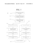
[0015] FIG. 1 is a view of the process of the present invention.
[0016] FIG. 2 is a view of the target sheet of the present invention.
[0017] FIG. 3 is a view of the process of the present invention.
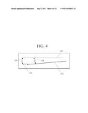
[0018] FIG. 4 is a view of the process of the present invention.
[0019] FIG. 5 is a view of the process of the present invention.
[0020] FIG. 6 is a view of the process of the present invention.
[0021] FIG. 7 is a view of the process of the present invention.
[0022] FIG. 8 is a view of the process of the present invention.
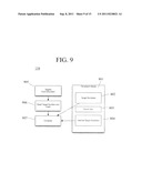
[0023] FIG. 9 is a view of the process of the present invention.
[0024] FIG. 10 is a view of the process of the present invention.
[0025] FIG. 11 is a view of the process of the present invention.
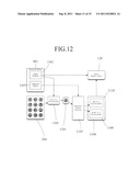
[0026] FIG. 12 is a view of the process of the present invention.
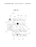
[0027] FIG. 13 is a view of the process of the present invention.
[0028] FIGS. 14A-C are views of the process of the present invention.
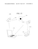
[0029] FIG. 15 is a view of the system of the present invention.
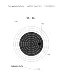
[0030] FIG. 16 is a view of the system of the present invention.
DETAILED DESCRIPTION
[0031] Referring first to FIG. 1, a basic embodiment of the process 100 of measuring a high-velocity puncture in a substantially planar object is shown. The process 100 includes disseminating 102 planar target sheets derived from a set of predefined stored template target sheet images. The stored template target sheet images are an electronically-stored collection of one or more target sheet images. The template target sheet images are preferably stored in persistent memory. Different target sheet images within the set of stored template target sheet images contain different visual or informational attributes that may relate to identification, target arrangement, security, display, etc.
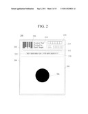
[0032] As shown by FIG. 2, the target sheet images contain the information pertinent to create a target sheet 200. The target sheet 200 includes a target section 204 with a space color and bull color, target sheet information, and reference data. The target sheets 200 are printed on paper and include two main sections: the target area 204 and information section 202. The target section 204 includes a space 208 and a bull 206 (or "aiming mark"). The bull 206 is the natural aiming element for the shooter and the space 208 surrounds the bull 206 to provide visual contrast for the bull 206. The target section 204 may have one or more bulls 206. FIG. 2 illustrates a target section 204 with only one aiming mark. The size and shape of the aiming mark is determined by the applicable national governing body rule book. Scoring rings may be printed on top of the aiming mark for the shooter's reference. For reasons that will be later discussed, it is preferred, but not necessary, to omit scoring rings from the bull 206.
[0033] Although FIG. 2 shows the information section 202 as distinct from the target area 204, these sections may overlap. The information section 202 may include a target serial number 222 and target scheme identifier 220. Each target sheet 200 may be individually and uniquely numbered. Printed with each target number 222 is the target security code 210. The target security code 210 may include any secured alphanumeric device, but is preferably derived from the target number 222, a secret key, and a hashing or encrypting function--such as MD5. The target number 222 and the target security code 210 together create a secured target. Secure targets allow a match director to give a shooter a set of paper targets at the beginning of the match and then verify that the paper targets returned by the shooter are identical to the targets initially disseminated.
[0034] The target scheme identifier 220 is shown in FIG. 2 as a barcode. The target scheme identifier 220 permits the process 100 of the present invention to quickly and accurately identify the target scheme. By target scheme, it is meant the attributes of the target, including position and size data related to the bull 206, position and size data related to the space 204, position data related to informational elements 218, 216, 214, 210, 222, and size and position date related to the reference data. The reference data preferably includes at least one reference line 212 and a reference point. Using barcodes as the scheme identifier mark is particularly useful since the technology is well known, proven, and readily available. Once the target scheme is known all other target element locations and dimensions may be looked up in a predetermined database such as the look up table of FIG. 3. For example, the target scheme may identify the first aiming bull to be 10.0 cm down and 4.0 cm to the right of the reference point. The reference point will be unique to each target and known based on the target scheme. It will be an easily identifiable location on the target, such as the left most point on the reference line 212.
[0035] The reference line 212 is used in conjunction with the reference point (the reference point and reference line may be correlated). The reference line 212 is used to measure the angle at which the target was captured. Although FIG. 2 only shows a single reference line, multiple reference lines may be used as well. If a target sheet image was captured using a digital camera the multiple reference lines may be used by the process to correct for distortions in the camera lens.
[0036] The target sheet 200 includes a competitor number box 216. Competitors in a match may be given a unique competitor number. To correlate shooter to target the competitor number is written or pre-printed on the target sheet 200. If written by hand or printed using characters the process may use existing optical character recognition (OCR) technology to identify the competitor. Other methods of preprinting the competitor number may also be used, such as bar codes. An event identifier 214 includes an event and series identification box. Similar to the competitor number box this information may be used to automatically determine which shot or series of shots the target represents in the match. The information may be pre-printed or filled in by the competitor. The target sheet 200 may include pre-printed text 218 that can be customized on a per-target basis. The text may contain, for example, the name of the match, the name of the shooter, or the name of the shooter's team.
[0037] Returning to FIG. 1, after the target sheets are disseminated 102 to shooting participants, the targets will receive high-velocity punctures. The nature of the present invention is such that substantially circular punctures within, or depicted upon, a 2-dimensional object/array are required. The substantially circular punctures are formed by the high speeds of the projectiles used with the present invention. Suitable projectiles may include bullets, arrows with heads adapted to form circular apertures, and other projectiles with heads adapted to form substantially circular apertures. Substantially circular apertures include ellipses and other generally curved, continuous geometric entities. An image of the punctured target sheet is captured electronically and transmitted 104 to a processing unit, e.g. a computer, with an arithmetic logic unit ("ALU"). It is preferred that the image is captured with a conventional off-the-shelf ("COTS") scanning device, digital camera, or other device adapted to electronically capture and transmit an image according to a machine readable language. Certain image capture devices are preferred over others for certain uses of the present invention. For example, a flat bed scanner, or a scanner with an automatic document feeder is preferred for 10 m air rifle targets because a scanner does not have nearly the lens distortion of a camera. Diminished distortion promotes more accurate analysis of the target sheet. Air rifle targets require the most accurate scoring of all current types of targets. On the opposite extreme, scoring a 600 yard rifle target necessitates a digital camera. The target's width is 72 inches and cannot fit upon any known COTS scanner. The best way to capture an image of such a target is to use a digital camera.
[0038] The target image file used in the present invention may leverage existing image file formats such as JPEG or PNG. As is true with the image capture device, not all image file formats are preferred for the process 100. For example to score air rifle targets, which requires the highest degree of accuracy, the image file should be lossless. A lossy file format adds side effects to the image that weaken the shot location algorithm's accuracy. The target image may either be stored on persistent media prior to substantial analysis, or the target image file may be passed directly into the ALU.
[0039] The captured image with the punctured target is then calibrated 106 by comparing the captured image to reference data of the stored template that correlates to the captured target. In order to ascertain which of the stored templates corresponds to the captured target sheet image, the process 100 recognizes the target scheme, for example by visual recognition of the target scheme bar code. The target identification mark is preferably located near one of the four corners of the target sheet image. The four corners of the captured target sheet image are scanned in a search for the identification mark. Once found the mark can be read using existing computer vision technique and the corresponding target scheme of the stored target template set is determined.
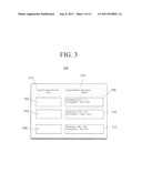
[0040] Once the target scheme is known, the dimensions of the target, the location of target elements, and all other information necessary to correctly identify and score the target may be looked up. The collective set of dimensions, location of elements, and additional information for scoring is known as the target scheme. The target scheme look up table ("LUT"), shown in FIG. 3 item 300, may be known a priori and stored on persistent media. Each known target scheme is listed in the "key" portion 314 of the look up table (example keys are items 302, 304, and 306). The "value" portion 316 (example values are items 308, 310, and 312), that contains the target dimensions and element locations, is read from the look up table and passed to the other stages of the process. A target scheme number that is not in the target scheme LUT results in an error. After the subject target sheet is determined, the reference data is utilized to determine correction data.
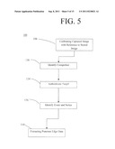
[0041] Returning to FIG. 1, when images are captured they are rarely captured in such a way that horizontal and vertical lines match up exactly to the x and y direction of the image. In order to locate elements on the target image the process 100 needs to correct for any alignment errors during image capturing steps of the present invention. To properly calibrate 106, the target scheme is used to identify the location of one or more reference lines. Once the general location of the reference line is known, based on the target scheme, existing computer vision techniques, e.g. Hough's Transform, may be used to locate the reference line's position and angle. As FIG. 4 illustrates, an expected reference line 320 whose dimensions and position is gleaned from the set of stored template target sheets is compared with the found reference line 322. From this information the error in the x direction, dx, 324, error in the y direction, dy, 326, and error in the angle, dθ, 328 may be calculated. The alignment process may also include corrections due to camera lens distortion. This again may be performed using the known reference lines and geometric camera calibration techniques. The calibrating process 106 may either create as calibrated data a new corrected target image or it may send the original target image with the dx, dy, dθ values to the later stages of the process 100.
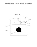
[0042] Turning now to FIGS. 5 and 6, competitor identification 130 includes correlating a shooter with a target. Competitor identification is performed by locating the competitor number box 216. Position data and dimensions of the competitor number box 216, and other visual elements, is located within the target sheet image by knowing the location of the reference mark 226. The location of the reference mark 226 is part of the target scheme definition, which is determined through identifying the target scheme through, for example, analysis of the target sheet bar code (not shown). The reference mark 226 may be any element that is visibly recognizable by a machine and has a location that is known or capable of being known to a reader. The difference between the reference marks expected and exact location is given by the calibration 106. As an offset to the reference mark 226 the x distance 228 and y distance 230 to the competitor number box 216 is given by the target scheme. A competitor identification sub-image with x dimension 232 and y dimension 234 is extracted from the target sheet 200. The x and y dimensions of the competitor number box 216 are provided by the target scheme as stored in persistent data. Depending on how the competitor number is printed, which may be specified in the target scheme, existing OCR, bar code reader, or similar computer vision techniques may be used to read and identify the competitor number.
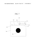
[0043] Turning now to FIG. 7, event and series identification 136 includes the means of determining which shot or series of shots the target represents. Event and series identification 136 is performed by locating the event and series box 236. Position data and dimensions of the event and series box 236, and other visual elements, are located within the target sheet 200 image by determining the location of the reference mark 226. The location of the reference mark 226 is part of the target scheme definition, which is determined through identifying the target scheme through, for example, analysis of the target sheet bar code (not shown). The difference between the reference marks expected and exact location is given by the calibration 106. As an offset to the reference mark 226 the x distance 228 and y distance 230 to the event and series box 236 is given by the target scheme. A competitor identification sub-image with x 232 and y 234 dimensions is extracted from the target sheet 200. The x and y dimensions of the event and series box 236 are provided by the target scheme as stored in persistent data. Depending on how the competitor number is printed, which may be specified in the target scheme, existing OCR, bar code reader, or similar computer vision techniques may be used to read and identify the competitor number.
[0044] Returning to FIG. 5 with reference to FIG. 8, target authentication 134 is the means by which the match personnel can verify that the target sheet turned in by the shooter is the same target given to the shooter at the start of the match and begins with effective target sheet dissemination 102. In order to authenticate 134 a target, the target is preferably marked with a unique number and hash code during the dissemination step. In the authentication means 134, prior to the start of the match the match director may assign 802 a unique target number (or set of unique target numbers) to each shooter. The mapping between shooters and target numbers is recorded on persistent media 801. The match director or another trusted individual creates a secret key 803. Each target number is concatenated with the secret key 803. The concatenated string is scrabbled 805 using a secure one way hashing function such as MD5. The result is a hashed string 804 that is stored back to the persistent media 801. There is one hashed string for each target number. Both the target number 802 and corresponding hash code 804 are printed on the target 804 in a location that is known by the target scheme. The resulting targets are then distributed 807 out to the corresponding shooters at the start of the match. It is preferred that each target number is used only once.
[0045] Turning now to FIGS. 5 and 9, once firing is complete for an event the shooters return the targets 905 to the match director. The target number and hash code may be read from the target 906. The location of the target number and hash code is found in the calibration step 106. The location is known by the target scheme, a sub-image can be extracted, and existing OCR or similar technique may read the target number and secure hash code.
[0046] The read target number and hashed string from 906 is compared against the stored target number 802 retrieved from persistent media 801 in a comparison 907. If the read value and stored value are not equal the shooter turned in a target other than the one the match director handed out at the start of the match. If the values are equal the target is authenticated 134.
[0047] Returning to FIG. 1, in shooting match scoring there are numerous parameters that are needed to correctly and quickly find the data of interest (e.g. the edge of the shot hole). These parameters such as the color of the shot hole and color of the aiming mark are known within small range of values. Variations in the digital image capture device, printing process of the paper target, and even the gun and ammo combination will cause errors in the expected parameter values. Unaccounted, these variations can cause havoc within the scoring algorithm. The extraction steps 110, 120 determine an appropriate set of parameters to use during the process 100 of the present invention. The extraction 110, 120 may be applied on each target for best accuracy (and slowest scoring speed) or to a set of targets where the process 100 is based on one target and the remaining targets are scored with the assumption that the parameters have not changed significantly, which in practice is generally true.
[0048] There are five general parameters that need to be calculated per target sheet. The parameters include the color of the aiming mark, the color of the aiming white space, the color of the bullet hole, shot hole characteristics, and aiming mark characteristics. The characteristics of the shot hole and aiming mark are dependent on the type of shooting (e.g. air rifle or centerfire pistol), the type of target (identified by the target scheme), and the image capture device (e.g. scanner or digital camera). For example if air rifle targets are being analyzed, scanned in with a scanner, then only the average radius of the bullet hole and average radius of the aiming bull needs to be calculated 112. The target scheme will offer the characteristics that need to be calculated.
[0049] A paper target when digitized to an image has three general groups of colors, the aiming white space, the aiming mark, and the bullet hole. Identifying and differentiating between these three colors is important to the accuracy and speed of target scoring. The color of the aiming white space is generally ivory or white. The color of the aiming mark is generally black, although other colors may be used. The color of the bullet hole is dependent on the image capture device. Although often white or black, it may comprise virtually any color.
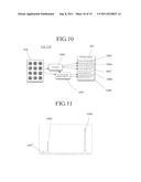
[0050] FIG. 10 illustrates the extraction process 110, 120. A representative target section 204 is used to determine the color values through histogram analysis 1002 and to determine 1003 the average bull and bullet hole dimensions. The resulting parameters, specifically the aiming black color 1005, aiming white color 1006, bullet hole color 1007, aiming mark dimensions 1008, and bullet hole dimensions 1009 are stored to persistent media 801 for use in the process 100 at a later time.
[0051] The histogramming process 1002 is performed by selecting a representative sample of images from the target section 204. An array of all possible colors is initialized to zero. The color of each pixel within the set of target images is taken. The array index corresponding to that color is incremented. This is repeated for all pixels in the image. The result is a histogram similar to that of FIG. 11. For demonstration purposes FIG. 11 was taken from a gray scale image where the pixel color is a value between 0 and 255. There are three local maximums. The maximum closest to the expected aiming white color is the calculated color of the aiming white space 1006. The local maximum closest to the expected aiming black color is the calculated color of the aiming bull black 1005. The third local maximum, where ever it may lie, is the color of the shot holes 1007.
[0052] On most targets the aiming bull is a black circle filled in with multiple, concentric aiming lines. The size of the aiming mark is governed by applicable rule books, therefore the size should be known a priori. However due to variations in the target printing and the image capture phase the expected dimension may not be the actual dimensions. To calculate the dimension and to use it across multiple scoring runs the present invention utilizes an assumption: the dimension of the aiming bull as seen within a target sheet image is consistent across target sheet images taken with the same digital capture device and target printing lot.
[0053] The present invention works ideally with an aiming bull that includes a uniform fill. That is to say, that only a single color is present within the bull. A bull free from aiming lines permits the present invention to operate with minimal complexity and obviates the need to account for line colors in the extraction steps of the present invention. In such embodiments where the aiming bull does include aiming lines, the present invention may account for the aiming lines by providing aiming lines of a known color distinct from the space color, bull color, and likely puncture color. In the alternative, the color of the aiming lines may match that of the space--which is usually white--and utilize reference data to predict position data related to the aiming marks and provide information to the present invention describing the expected amount of aiming line color per pixel of the captured image.
[0054] Returning to FIG. 1, the aiming bull, or aiming mark, extraction 120 seeks to find the average dimension of the aiming mark as it appears on the target images. Existing computer vision geometric fitting techniques (e.g. Hough's transform) in conjunction with statistical sampling may be used to complete this task. A similar process may be used to find the characteristics of the shot holes. In practice though, the shot hole calibration process needs more samples than the bullet hole calibration process as shot holes tend to have significant tearing and irregular shapes, even in holes caused by high-velocity projectiles. To compensate for this extra noise multiple bullet hole samples are preferably utilized. However the basic means for extracting aiming mark data may be used to extract shot hole data.
[0055] As with the assumption regarding the dimension of the aiming bull, a similar assumption about the bullet hole diameter is made. The bullet hole diameter is assumed to be constant across multiple shots on multiple targets. This assumption is generally true for the same gun and ammo combination. However the assumption breaks down across different gun and ammo combinations. A method to adjust 116, 126 for error inherent in the standardized dimension of the bull and shot hole is part of the present invention 100.
[0056] Hough's transform, the geometric fitting process used to find the center of the aiming bull and bullet holes during scoring is an O(x3) problem. The calculating 112, 122 steps set one of the dimensions (namely the radius or diameter) to a fixed value. The calculating step is performed as the present invention uses visual recognition means to aggregate dimensions of multiple projectile holes and derive a standard dimension based on the aggregation. The aggregation may be based on two or more projectile holes. It is preferred that the standard dimension is simply the average of a known dimension value, e.g. radius, dimension, etc. However, any standard dimension that is based on the aggregation is part of the present invention and includes a standard dimension that is, e.g. 110%, 120%, 200%, or 300% of the aggregation average. Furthermore, the standard dimension may be the median of the aggregation values. It is preferred that the aggregation value, if, by way of example, includes the diameter, is equal to or greater than the average of the aggregation values, but no larger than three times the average of the aggregation values. However, the present invention includes all determinations of a standard dimension that is constantly applied across multiple reviewed projectile holes. Providing a standard dimension reduces the processes' computational complexity to O(x2). The complexity is in finding the x and y coordinates. This results in a significant speed up during scoring without compromising accuracy. Note that this discussion assumes the target image was captured using a scanner and has a circular aiming mark, if the target image was captured using a digital camera the fitting process may be a O(x5) problem. However providing a standard dimension would still reduce complexity of the analysis, notwithstanding the use of the less accurate digital camera transmission, to find the x and y coordinates of each shot.
[0057] Scoring 128 is the means of determining the center of the aiming mark and the center of each shot hole, comparing the difference, and looking up or calculating the score value of a shot. This process is further illustrated in FIG. 12.
[0058] Each target section 204 is read and separated 1105 into a set of smaller single bull sub-images one per aiming bull 206. The number and location of each aiming bull is provided by the target scheme. The single bull images 1201 are passed to the geometric fitting process 1107. The output of the fitting process 1107 is the x and y location of the aiming mark and bullet holes (each sub-target may have zero, one, or more shots on it). Also as output is an accumulation value. It has been found that the accumulation value may be used as a measure of the shot's accuracy. The greater the value the more precisely the shot's location is known.
[0059] Using the accumulation value as a metric for the accuracy of the shot location is an aspect of the present invention. Traditional paper targets scoring offers no quantifiable metric for a shot value's accuracy. A shot's score value is determined 128 based on the aiming mark location, bullet location, and the rules established by the governing bodies. These rules are passed into the scoring means 128 by the target scheme 1102. Traditional paper targets have pre-printed scoring rings that determine the value of a shot. ESTs use an electrical center. In many ways calculating the center of the aiming mark is better than paper targets or ESTs. Paper targets (beyond human errors in scoring) suffer from inconsistent variations in the printing process and have been known to shrink or expand due to temperature and humidity. With ESTs, a shooter aims at a target or aiming mask and has to adjust his or her sights to the electrical center of the EST and not the center of the aiming mask. In practice the center of the aiming mask and the electrical center of the EST are very close. The danger associated with an EST is that the aiming mask moves during the competition, thus the shooter is no longer aiming and shooting at the electrical center of the target. With the present invention both the shooter and the scoring process use the exact same aiming mark.
[0060] The details of the geometric fitting process 1107 are shown in FIG. 13. There are largely two parallel paths in the fitting process. One path to locate the center of the aiming mark, the second path to locate the center of the bullet hole. With the exception of input parameters these processes are nearly identical.
[0061] A single aiming mark image 1201 is the input. The first step is segmentation 1204. In this step each pixel in the image is categorized as either the reference color 1007 or "other." This effectively creates a binary image 1205 showing only the bullet hole. The edge of the bullet hole is extracted 1206 using an edge detection algorithm. The resulting image 1207, shows only the edge of the bullet hole. The bullet hole edge image 1207 is passed to the Hough transform process along with the expected bullet dimension previously determined in the extraction process 1003. The result is a two dimensional array 1213 the same size as the original target image 1201 where each index value represents the possibility that a shot was centered there. As an adjustment step 1214, the process finds the x and y index values above a predetermined threshold from the target scheme 1202. These x and y index values represent a shot's location. The adjuster 1214 also uses statistical sampling from neighboring index values to achieve sub-pixel resolution.
[0062] With reference to FIGS. 1 and 13, sub-pixel adjustment 116, 126 helps to account for quantization error during the image capture phase and more importantly compensates for using an average radius value for the bullet diameter (that was calculated for in the extraction steps 110, 120. As discussed previously an assumption is made that all bullet diameters will be the same. This is a false assumption, but a practical one to find bullet holes in O(x2) time. Sub-pixel resolution processing works very quickly and significantly reduces the error caused by the constant radius assumption. The x and y index is returned as the shot's location 1215. In addition the index value is returned as the accumulation value 1215. The accumulation value, which as discussed earlier, allows the present invention to give a quantifiable measure of each shot's accuracy.
[0063] The process to locate the center of the aiming mark is nearly the same. Segmentation 1208 occurs between the color of the aiming mark and everything else. Edge detection 1210 detects the binary version of the aiming bull 1209 and the edge of the aiming mark 1211. Hough transform is performed 1216 to generate a two dimensional accumulation array 1217. Bull identification 1218 is slightly different since each image may only have one bull. Instead of finding any x and y index above a threshold, only the maximum index value is found. The index with the maximum value is the center of the aiming mark. A sub-pixel resolution 1218 determined through an adjustment function 1292 returns a value 1219 that is the x and y location of the bull and the index value as the accumulation
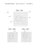
[0064] FIGS. 14A-C with reference to FIG. 1, depict the determining steps 114, 124 of the present invention. The adjustment function 1292 includes edge data related to the puncture hole 1406 arranged according to a 2-dimensional pixel array file 1402. The standardized dimension 1408, shown as a radius, is applied and a fit circle 1410 with a radius having the standard dimension is applied to each pixel 1404 that includes the puncture circle periphery 1406. For each placement of the fit circle 1410, each pixel within the fit circle receives a score. An accumulation array includes accumulation values bearing the sum of scores for each pixel. The pixel with the highest value in the accumulation array is the likely center of the puncture hole. The likely center is a very reliable estimate of the puncture center. The present step is used to determine the likely center of both the bull aiming mark and the bullet puncture. The achieve subpixel resolution, the process 100 of the present invention further includes adjustment 116, 126. A weighted average of the surrounding pixels is taken to achieve an adjusted center. The adjusted center is highly accurate and surrounding pixel values may be included to proffer a reliability score for the center measurement. The adjustment function may operate along similar lines to determine more accurately a center based on an accumulation value for the bull location, and more particularly, the bull center.
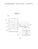
[0065] As FIG. 15 shows, the system 1300 of the present invention includes a printing device 1306, target sheet 200, reproduction/transmission device 1302, and processor device 1304 having an ALU and persistent memory. The system 1300 performs the process by accessing data within the persistent memory to send to the printing device 1306 data sufficient to generate target sheets 200 for dissemination. An image of the target sheet, subsequent to high-velocity puncturing, is transmitted to the ALU of the processor device 1304, which may be identical or different from the processing device that printing the target sheets. The ALU performs the target sheet analysis steps of the present invention.
[0066] The system 1300 includes a transmitter function for transmitting a captured image of at least one target sheet bearing at least one high-velocity puncture to the ALU, which performs the functions and other steps of the process of the present invention. A calibration function calibrates said captured image of said punctured target sheet by comparing the captured image to reference data of a correlating stored template target sheet image to produce correction data. An extraction function extracts from the punctured target sheet image puncture edge data characterizing the periphery of at least two of the punctures and color data related to the puncture. A calculator function collects from the captured image a standard puncture dimension based on the puncture edge data of at least two of the punctures. An identification function identifies a likely puncture center point for a reviewed puncture from the captured image as a function of said correction data, puncture edge data from the reviewed puncture, and a 2-D index of puncture accumulation values from the standard puncture dimension repeatedly overlayed according to said puncture edge data of said reviewed puncture. The system may further include an adjusting function for adjusting the likely puncture center point based on neighboring index values to produce an adjusted puncture center point. The system may further include a bull extraction function for extracting from the punctured target sheet bull edge data characterizing the periphery of at least two of the bulls and color data related to the bull; a bull calculator function for collecting from the captured image a standard bull dimension based on the bull edge data of at least two of the bulls; a bull identification function for identifying a likely bull center point of a reviewed bull as a function of the correction data, bull edge data from the reviewed bull, and a 2-D index of bull accumulation values from the standard bull dimension repeatedly overlayed according to the bull edge data; and a bull adjustment function for adjusting the likely bull center point based on neighboring bull index values to produce an adjusted bull center point.
[0067] Turning now to FIGS. 10, 13, and 16, the output of process 1107 may include a puncture overlay map 1500. The puncture overlay map 1500 may include the x and y location and a reliability indicator 1506, particularly a quantifiable reliability score, of the circular aiming bull and the bullet puncture. While the reliability score 1506 may be used to quantifiably measure the accuracy of the scoring process 100, another method may be used to show qualitative accuracy to human operators. The image 1201 may be replicated to a new image. The ALU may then enhance the image by drawing a puncture overlay circle 1502 with the puncture diameter 1008, known from the calibration values, with center at the computed x and y location value 1219 of the puncture hole. In similar fashion this image may again be enhanced by drawing a bull overlay circle 1504 with the aiming bull diameter 1008, known from the calibration values, with center at the computed x and y location value 1215 of the aiming bull. The resulting image may be saved to persistent media or displayed to the human operator using existing graphical programs. The human operator may visually inspect and compare the computed puncture location with the puncture displayed in the graphic, as well as compare the computed bull location with the bull displayed in the graphic
[0068] Although the present invention has been described in considerable detail with reference to certain preferred versions thereof, other versions would be readily apparent to those of ordinary skill in the art. Therefore, the spirit and scope of the appended claims should not be limited to the description of the preferred versions contained herein.
User Contributions:
Comment about this patent or add new information about this topic:
Images included with this patent application:
 |  |
 |  |
 |  |
 |  |
 |  |
 |  |
 |  |
 |
| New patent applications in this class: | |
| Date | Title |
|---|---|
| 2019-05-16 | Gaming system in which skill level is determined and used to vary game play difficulty |
| 2017-08-17 | Gaming object with orientation sensor for interacting with a display and methods for use therewith |
| 2017-08-17 | Game console and gaming object with motion prediction modeling and methods for use therewith |
| 2016-06-30 | An interactive laser tag system and a method of using the same |
| 2016-04-21 | Electronic device displays an image of an obstructed target |
| Top Inventors for class "Amusement devices: games" | |
| Rank | Inventor's name |
|---|---|
| 1 | Jay S. Walker |
| 2 | Mark B. Gagner |
| 3 | Kazumasa Yoshizawa |
| 4 | Alfred Thomas |
| 5 | Mark C. Nicely |