Patent application title: Deactivating a Power Source
Inventors:
Bouziane Yebka (Apex, NC, US)
Bouziane Yebka (Apex, NC, US)
Joseph Anthony Holung (Wake Forest, NC, US)
Joseph Anthony Holung (Wake Forest, NC, US)
Tin-Lup Wong (Chapel Hill, NC, US)
Kenneth Scott Seethaler (Wake Forest, NC, US)
Kenneth Scott Seethaler (Wake Forest, NC, US)
IPC8 Class: AB60K104FI
USPC Class:
180 651
Class name: Motor vehicles power electric
Publication date: 2011-09-08
Patent application number: 20110214928
Abstract:
A battery is disclosed that includes two contact areas, an electrolyte,
and a conductivity mechanism to increase electron conductivity internal
to the battery between the two contact areas that, in turn, deactivates
the battery. In one embodiment, the conductivity mechanism is triggered
external to the battery. In another embodiment, the conductivity
mechanism utilizes deactivator material to increase electron conductivity
through the electrolyte to deactivate the battery. In yet another
embodiment, the conductivity mechanism creates multiple shorts between
the two contact areas to deactivate the battery.Claims:
1. A system comprising: a battery comprising: a first contact area and a
second contact area, wherein the first contact area is negatively charged
relative to the second contact area; an electrolyte that couples to the
first contact area and to the second contact area, wherein the
electrolyte suppresses electron flow internal to the battery between the
first contact area and the second contact area and enables ion flow
internal to the battery between the first contact area and the second
contact area: and a conductivity mechanism to increase electron
conductivity between the first contact area and the second contact area
internal to the battery.
2. The system of claim 1 wherein the conductivity mechanism includes a material receptor to receive deactivator material that causes the increased electron conductivity internal to the battery through the electrolyte between the first contact area and the second contact area.
3. The system of claim 2 further comprising: the deactivator material; and a deactivator mechanism for invoking the deactivator material to release through the material receptor and into the electrolyte, wherein the deactivator mechanism is activated external to the battery.
4. The system of claim 3 further comprising: a temperature sensor for initiating one or more actions in response to detecting a deactivation trip point temperature, in response to the one or more actions the deactivator mechanism invoking the deactivator material.
5. The system of claim 3 wherein the deactivator material is electronically conductive.
6. The system of claim 3 wherein the deactivator material is electronically non-conductive and creates an electronically conductive combination material when the deactivator material is combined with the electrolyte.
7. The system of claim 1 wherein the conductivity mechanism, when invoked external to the battery, creates a plurality of shorts between the first contact area and the second contact area, the plurality of shorts increasing the electron conductivity between the first contact area and the second contact area internal to the battery.
8. The system of claim 1 wherein the battery comprises a plurality of cells and the electrolyte resides within the plurality of cells.
9. A system comprising: one or more system components that consume power; a battery pack that provides power to the one or more system components, wherein the battery pack comprises: a battery comprising: a first contact area and a second contact area, wherein the first contact area is negatively charged relative to the second contact an electrolyte that couples to the first contact area and to the second contact area, wherein the electrolyte suppresses electron flow internal to the battery between the first contact area and the second contact area and enables ion flow internal to the battery between the first contact area and the second contact area: and a conductivity mechanism for increasing electron conductivity between the first contact area and the second contact area internal to the battery; and a deactivator mechanism that is invoked external to the battery, wherein, when invoked, triggers the conductivity mechanism to increase the electron conductivity between the first contact area and the second contact area internal to the battery.
10. The system of claim 9 wherein the one or more system components further comprise: one or more processors; a memory accessible by at least one of the processors; and a nonvolatile storage area accessible by at least one of the processors.
11. The system of claim 9 wherein the one or more system components comprise a motor included in a transportation vehicle, wherein the motor receives power from the battery pack in order to propel the vehicle.
12. The system of claim 9 wherein the conductivity mechanism includes deactivator material that causes the increased electron conductivity through the electrolyte between the first contact area and the second contact area
13. The system of claim 10 wherein the conductivity mechanism includes a material receptor to permit the deactivator material to enter into the electrolyte.
14. The system of claim 13 further comprising: a temperature sensor for detecting the battery reaching a deactivation trip point temperature, the deactivation trip point temperature initiating the deactivator mechanism to invoke the deactivator material through the material receptor.
15. The system of claim 12 wherein the deactivator material is electronically conductive.
16. The system of claim 12 wherein the deactivator material is electronically non-conductive and creates an electronically conductive combination material when the deactivator material is combined with the electrolyte.
17. The system of claim 12 wherein the conductivity mechanism, when invoked by the deactivator mechanism, creates a plurality of shorts between the first contact area and the second contact area, the plurality of shorts increasing the electron conductivity between the first contact area and the second contact area internal to the battery.
18. A method for producing a battery, the method comprising: including a first contact area and a second contact area in the battery, wherein the first contact area is negatively charged relative to the second including an electrolyte in the battery that couples to the first contact area and to the second contact area, wherein the electrolyte suppresses electron flow internal to the battery between the first contact area and the second contact area and enables ion flow internal to the battery between the first contact area and the second contact area: and including a conductivity mechanism in the battery to increase electron conductivity between the first contact area and the second contact area internal to the battery.
19. The method of claim 18 further comprising: including a material receptor in the battery to receive deactivator material that causes the increased electron conductivity internal to the battery through the electrolyte between the first contact area and the second contact area.
20. The method of claim 19 further comprising: including the deactivator material in the battery; and including a deactivator mechanism on the battery for invoking the deactivator material to release through the material receptor and into the electrolyte, wherein the deactivator mechanism is activated external to the battery.
21. The method of claim 19 further comprising steps of: including a temperature sensor on the battery for initiating one or more actions in response to detecting a deactivation trip point temperature, in response to the one or more actions the deactivator mechanism invoking the deactivator material.
22. The method of claim 19 wherein the deactivator material is electronically conductive.
23. The method of claim 19 wherein the deactivator material is electronically non-conductive and creates an electronically conductive combination material when the deactivator material is combined with the electrolyte.
Description:
TECHNICAL FIELD
[0001] Subject matter disclosed herein relates to deactivating a power source, and more particularly relates to increasing a battery electrolyte's electronic conductivity in order to deactivate the battery.
BACKGROUND
[0002] Batteries are used extensively in notebook computers, cell phones, tools, transportation vehicles (e.g., electric cars, trains, buses, etc.), and other systems that depend upon an electrical source to function. Rechargeable batteries, such as lithium-ion batteries, may be the battery of choice due to their relative low cost and high energy storage capability.
[0003] A battery uses chemical energy (internal ion transfer) to perform electrical work (external electron transfer). A battery includes two external contact areas (anode and cathode) and an electrolyte. The anode is negatively charged relative to the cathode and, by connecting the anode and cathode to an electronic load, the battery provides power to the electronic load by passing electrons from the anode to the load and back to the cathode. The electrolyte is an ion conductor and an electron insulator. Meaning, the electrolyte passes ions between the anode and cathode, but suppresses electron flow between the anode and cathode. As the battery passes electrons to the electron load (discharges) through its external contacts, the electrolyte passes ions from the anode to the cathode internal to the battery.
SUMMARY
[0004] A battery is disclosed that includes two contact areas, an electrolyte, and a conductivity mechanism to increase electron conductivity internal to the battery between the two contact areas that, in turn, deactivates the battery. In one embodiment, the conductivity mechanism is triggered external to the battery. In another embodiment, the conductivity mechanism utilizes deactivator material to increase electron conductivity through the electrolyte to deactivate the battery. In yet another embodiment, the conductivity mechanism creates multiple shorts between the two contact areas to deactivate the battery.
[0005] The foregoing is a summary and thus contains, by necessity, simplifications, generalizations, and omissions of detail; consequently, those skilled in the art will appreciate that the summary is illustrative only and is not intended to be in any way limiting. Other aspects, inventive features, and advantages of embodiments of the present disclosure, as defined solely by the claims, will become apparent in the non-limiting detailed description set forth below.
BRIEF DESCRIPTION OF THE DRAWINGS
[0006] Features and advantages of the described implementations can be more readily understood by reference to the following description taken in conjunction with the accompanying drawings, wherein:
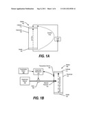
[0007] FIG. 1A is a diagram showing a battery generating internal ion flow and providing electron flow to an external load;
[0008] FIG. 1B is a diagram showing a battery receiving deactivation material to deactivate the battery;
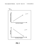
[0009] FIG. 2 is a graphical diagram showing relationships between electrolyte electron conduction, internal electron propagation, and battery voltage;
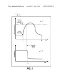
[0010] FIG. 3 is a graphical representation of a battery being deactivated after commencing a thermal runaway condition;
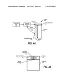
[0011] FIG. 4A is a diagram showing a battery that includes internal deactivator material, which is externally invoked by a deactivator mechanism;
[0012] FIG. 4B is a diagram showing an embodiment of a deactivator mechanism invoking deactivator material that is stored internal to a battery;
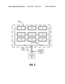
[0013] FIG. 5 is a diagram of a multi-cell battery embodiment that includes common electrolyte material;
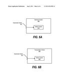
[0014] FIG. 6A is a diagram showing an electronic system utilizing a battery system with deactivation capabilities; and
[0015] FIG. 6B is a diagram showing a transportation vehicle utilizing a battery system with deactivation capabilities.
DETAILED DESCRIPTION
[0016] Certain specific details are set forth in the following description and figures to provide a thorough understanding of various embodiments of the disclosure. Certain well-known details often associated with computing and software technology are not set forth in the following disclosure, however, to avoid unnecessarily obscuring the various embodiments of the disclosure. Further, those of ordinary skill in the relevant art will understand that they can practice other embodiments of the disclosure without one or more of the details described below. Finally, while various methods are described with reference to steps and sequences in the following disclosure, the description as such is for providing a clear implementation of embodiments of the disclosure, and the steps and sequences of steps should not be taken as required to practice this disclosure. Instead, the following is intended to provide a detailed description of an example of the disclosure and should not be taken to be limiting of the disclosure itself. Rather, any number of variations may fall within the scope of the disclosure, which is defined by the claims that follow the description.
[0017] As will be appreciated by one skilled in the art, aspects of the present disclosure may be embodied as a system, method or computer program product. Accordingly, aspects of the present disclosure may take the form of an entirely hardware embodiment, an entirely software embodiment (including firmware, resident software, micro-code, etc.) or an embodiment combining software and hardware aspects that may all generally be referred to herein as a "circuit," "module" or "system."
[0018] Aspects of the present disclosure are described below with reference to flowchart illustrations and/or block diagrams of methods, apparatus (systems) and computer program products according to embodiments of the disclosure. It will be understood that each block of the flowchart illustrations and/or block diagrams, and combinations of blocks in the flowchart illustrations and/or block diagrams, can be implemented by computer program instructions. These computer program instructions may be provided to a processor of a general purpose computer, special purpose computer, or other programmable data processing apparatus to produce a machine, such that the instructions, which execute via the processor of the computer or other programmable data processing apparatus, create means for implementing the functions/acts specified in the flowchart and/or block diagram block or blocks. These computer program instructions may also be stored in a computer readable medium that can direct a computer, other programmable data processing apparatus, or other devices to function in a particular manner, such that the instructions stored in the computer readable medium produce an article of manufacture including instructions which implement the function/act specified in the flowchart and/or block diagram block or blocks.
[0019] The following detailed description will generally follow the summary of the disclosure, as set forth above, further explaining and expanding the definitions of the various aspects and embodiments of the disclosure as necessary.
[0020] FIG. 1A is a diagram showing a battery generating internal ion flow and providing electron flow to an external load. Battery 100 includes two external contact areas, which are cathode 110 and anode 130. For example, cathode 110 may be the "positive" side of battery 100 and anode 130 may be the "negative" side of battery 100. In one embodiment, both cathode 110 and anode 130 have high ionic conductivity and high electronic conductivity.
[0021] Battery 100 also includes electrolyte 120, which has high ionic conductivity and little to no electronic conductivity. For example, electrolyte 120 may include electrolytic material such as lithium salts (e.g., LiPF6, LiBF4 or LiCIO4) in an organic solvent, such as ethylene carbonate. When load 140 connects to battery 100, electrons flow from anode 130, through load 140, and back to cathode 110. In order for this to occur, ions flow from anode 130 to cathode 110 through electrolyte. In short, battery 100 uses chemical energy (internal ion transfer) to perform electrical work (external electron transfer).
[0022] Situations may arise when battery 100 requires deactivation. For example, battery 100 may be on the verge of thermal runaway or a hazardous condition, such as an electric car involved in an accident. In such cases, this disclosure describes embodiments that introduce deactivator material into electrolyte 120 and causes electrolyte 120 to become electronically conductive. When this occurs, the voltage potential between cathode 110 and anode 130 is significantly reduced and battery 100 becomes deactivated.
[0023] FIG. 1B is a diagram showing a battery receiving deactivation material to deactivate the battery. Battery 100 includes material receptor 140, which receives deactivator material 150 and releases deactivator material 150 into electrolyte 120. Deactivator material 150 is a conductivity mechanism that may be electronically conductive or an inert material that creates an electronically conductive combination material when combined with electrolytic material included in electrolyte 120, thereby creating multiple shorts internal to battery 100. In other embodiments, different conductivity mechanisms may be used to create multiple shorts in battery 100 for deactivation, such as having an area on battery 100 for a user to depress that couples metal fragments together.
[0024] During cell malfunction or heat exposure, the risk of thermal runaway or explosion is proportional to the voltage potential difference between cathode 110 and anode 130. To minimize or eliminate the risk of thermal runaway or explosion, deactivator material 150 is introduced into electrolyte 120 to increase electron conduction between cathode 110 and anode 130, thereby significantly reducing the voltage potential between cathode 110 and anode 130 (see FIGS. 2-3 and corresponding text for further details).
[0025] Deactivator mechanism 170 controls valve 160, which allows deactivator material 150 to reach material receptor 140. The embodiment shown in FIG. 1B shows deactivator mechanism 170 receiving input from deactivation button 180 and temperature sensor 190. Deactivation button 180 may be a button that a user pushes to deactivate battery 100. For example, in an emergency power off (EPO) configuration, deactivation button 180 may be located in proximity to an electric car's battery area. In this example, an emergency respondent may depress deactivation button 180 to inject deactivator material 150 into the car's battery system and disable the car's battery system. In one embodiment, deactivator button 180 and deactivator mechanism 170 are synonymous.
[0026] In another embodiment, temperature sensor 190 monitors the temperature of battery 100 to detect thermal runaway conditions. For example, localized heat that is triggered by low electrical resistance contact may lead to battery 100 overheating and thermal runaway. In this embodiment, deactivator mechanism 170 detects battery 100 reaching a "deactivation trip point temperature" (e.g., 130 degrees Celsius) and, in turn, invoking valve 160 to allow deactivator material 150 to release into battery 100. In turn, the voltage potential between cathode 110 and anode 130 is significantly reduced, thereby deactivating battery 100. As those skilled in the art can appreciate, other embodiments may be used to inject deactivator material 150 into electrolyte 120 (see FIGS. 4-5, and corresponding text for further details).
[0027] FIG. 2 is a graphical diagram showing relationships between electrolyte electron conduction, internal electron propagation, and battery voltage. Graphs 200 include graph 210 and graph 220. Graph 210 shows that as an electrolyte's electron conductivity increases (y-axis), the internal electron propagation between the anode and cathode increases (x-axis). And, as graph 220 shows, as the internal electron propagation between the anode and cathode increases (x-axis), the battery voltage decreases (y-axis). This is due to the fact that as electrons migrate from the battery's anode to the cathode, the voltage potential difference between the anode and cathode decreases. In short, by increasing the electrolyte's electronic conductivity, the battery's voltage potential decreases and deactivates the battery, therefore minimizing thermal runaway (see FIG. 3 and corresponding text for further details).
[0028] FIG. 3 is a graphical representation of a battery being deactivated after commencing a thermal runaway condition. Graphs 300 include graph 310 and graph 330. Graph 310 shows a battery's temperature at various points in time. At time t1, the battery is subject to an internal battery short. For example, the battery may have been damaged, or the battery may include defective material. As discussed previously, a low electrical resistance may trigger a localized heat condition and result in thermal runaway. The internal battery short causes the low electrical resistance and, as graph 310 illustrates, causes the battery's temperature to increase.
[0029] The battery's temperature continues to increase, and eventually reaches deactivation trip point temperature 320 at time t2 (e.g., detected by a temperature sensor). At this point, a deactivation mechanism invokes deactivator material into the battery, which causes the battery's electrolyte to become electronically conductive. For example, in the embodiment shown in FIG. 1B, deactivation mechanism 170 receives battery 100's temperature information from temperature sensor 190. Detecting that battery 100's temperature reached deactivation trip point temperature 320, deactivation mechanism 170 invokes valve 160 to release deactivator material 150 into battery 100.
[0030] As the battery's electrolyte becomes more conductive and electrons migrate from the battery's anode to cathode, the battery's voltage potential decreases (shown in graph 330). At time t3, the battery is deactivated (little to no voltage potential between the anode and cathode), which causes the battery's temperature to drop and eventually decrease to nominal levels at time t4 (graph 310).
[0031] FIG. 4A is a diagram showing a battery that includes internal deactivator material, which is externally invoked by a deactivator mechanism. Battery 400 includes cathode 410, electrolyte 420, anode 430, deactivator material 435 and material receptor 440. When deactivator 450 invokes deactivator material 435 to release through material receptor 440, deactivator material 430 enters electrolyte 420, thereby increasing electrolyte 420's electronic conductivity and deactivating battery 400. Deactivator mechanism 450 may receive input from deactivation button 455 or temperature sensor 460 as discussed previously. In one embodiment, deactivator mechanism 450 and deactivation button 455 may be synonymous (see FIG. 4B and corresponding text for further details).
[0032] FIG. 4B is a diagram showing an embodiment of a deactivator mechanism invoking deactivator material that is stored internal to a battery. Deactivator mechanism 470 may be, for example, a spring loaded puncturing device. When a user depresses deactivator mechanism 470, deactivator mechanism 470 punctures through material receptor 485. In turn, deactivator material 480 stored in housing 475 releases through material receptor 485 and into electrolyte 490, thereby increasing electrolyte 490's electronic conductivity as discussed previously. In one embodiment, material receptor 485 may be an area on the wall between housing 475 and electrolyte 490 for deactivator mechanism 470 to puncture.
[0033] FIG. 5 is a diagram of a multi-cell battery embodiment that includes common electrolyte material. Battery 500 includes multiple cells (e.g., an automotive battery), electrolyte material 510, and material receptor 520. In one embodiment, some of the cells may be coupled to an external anode contact area and other cells may be coupled to an external cathode contact area. In order to deactivate battery 500, deactivator mechanism 540 invokes valve 530 to allow deactivator material 550 to release through material receptor 520. Deactivator material 550 may be electronically conductive, or deactivator material 550 may combine with electrolyte material 510 to produce an electronically conductive material. In either case, electronic conductivity increases between the cells and deactivates battery 500. In one embodiment, electrolyte material 510 resides within the cells.
[0034] FIG. 6A is a diagram showing an electronic system utilizing a battery system with deactivation capabilities as discussed herein. Electronic system 600 may be, for example, a computer system, a cell phone, a medical device, an electronic toy, and etcetera. Battery system 610 includes a battery (anode, cathode, electrolyte, material receptor), deactivator material, deactivation mechanism, and may include a temperature sensor.
[0035] Battery system 610 may monitor the battery's temperature and deactivate the battery as discussed herein when the battery's temperature reaches a deactivation trip point temperature. In addition, a user may depress deactivation button 620 to deactivate the battery included in battery system 610. For example, a user may wish to ship a battery to a manufacture and, in this example, the user may depress deactivation button 620 to deactivate the battery, making the battery safe for shipment.
[0036] FIG. 6B is a diagram showing a transportation vehicle utilizing a battery system with deactivation capabilities as discussed herein. Transportation vehicle 630 may be, for example, an electric car, an electric bus, a commuter rail system with backup power capability, and etcetera. Battery system 640 may include a bank of batteries, deactivator material, deactivation mechanism, and may include temperature sensors.
[0037] Battery system 640 may monitor battery temperatures and deactivate the batteries as discussed herein when one of the battery's temperatures reaches a deactivation trip point temperature. In addition, a user may depress deactivation button 650 to deactivate the batteries included in battery system 640 as discussed herein. For example, a person may deactivate an electric car's battery bank when the electric car is involved in an accident. In this example, the person may assist an injured motorist without concern of being shocked.
[0038] The block diagrams in the Figures illustrate the architecture, functionality, and operation of possible implementations of systems, methods and computer program products according to various embodiments of the present disclosure. In this regard, each block in the flowchart or block diagrams may represent a module, segment, or portion of code, which comprises one or more executable instructions for implementing the specified logical function(s). It should also be noted that, in some alternative implementations, the functions noted in the block may occur out of the order noted in the Figures. For example, two blocks shown in succession may, in fact, be executed substantially concurrently, or the blocks may sometimes be executed in the reverse order, depending upon the functionality involved. It will also be noted that each block of the block diagrams and/or flowchart illustration, and combinations of blocks in the block diagrams and/or flowchart illustration, can be implemented by special purpose hardware-based systems that perform the specified functions or acts, or combinations of special purpose hardware and computer instructions.
[0039] While particular embodiments of the present disclosure have been shown and described, it will be obvious to those skilled in the art that, based upon the teachings herein, that changes and modifications may be made without departing from this disclosure and its broader aspects. Therefore, the appended claims are to encompass within their scope all such changes and modifications as are within the true spirit and scope of this disclosure. Furthermore, it is to be understood that the disclosure is solely defined by the appended claims. It will be understood by those with skill in the art that if a specific number of an introduced claim element is intended, such intent will be explicitly recited in the claim, and in the absence of such recitation no such limitation is present. For non-limiting example, as an aid to understanding, the following appended claims contain usage of the introductory phrases "at least one" and "one or more" to introduce claim elements. However, the use of such phrases should not be construed to imply that the introduction of a claim element by the indefinite articles "a" or "an" limits any particular claim containing such introduced claim element to disclosures containing only one such element, even when the same claim includes the introductory phrases "one or more" or "at least one" and indefinite articles such as "a" or "an"; the same holds true for the use in the claims of definite articles.
User Contributions:
Comment about this patent or add new information about this topic:
Images included with this patent application:
 |  |
 |  |
 |  |
| New patent applications in this class: | |
| Date | Title |
|---|---|
| 2022-05-05 | Fuel cell vehicle |
| 2019-05-16 | Electrically powered wheelchair |
| 2017-08-17 | Dual charge ride-on vehicle |
| 2016-12-29 | Electrolyte solution, method for producing electrolyte solution, and electrochemical device |
| 2016-07-14 | Battery pack and electric vehicle |
| New patent applications from these inventors: | |
| Date | Title |
|---|---|
| 2021-12-30 | System hinge assembly |
| 2021-11-04 | Variable temperature heat exchange switch |
| Top Inventors for class "Motor vehicles" | |
| Rank | Inventor's name |
|---|---|
| 1 | Yoshimoto Matsuda |
| 2 | Toru Takenaka |
| 3 | Daniel E. Williams |
| 4 | Shinji Ichikawa |
| 5 | Hiroshi Gomi |