Patent application title: CANOPY STRUCTURE
Inventors:
Stephen A. Konkle, Jr. (Kirkland, WA, US)
Assignees:
ANDERSON DAYMON WORLDWIDE, LLC
IPC8 Class: AE04H1534FI
USPC Class:
135121
Class name: Tent, canopy, umbrella, or cane portable shelter (i.e., tent or canopy) framework
Publication date: 2011-09-01
Patent application number: 20110209737
Abstract:
A canopy structure having a canopy supported by a plurality of elongated
support columns, each support column having a longitudinal cavity and an
opening at a first end thereof to provide access to the longitudinal
cavity. A container to receive a ballast material is positioned within
the longitudinal cavity of each of the support columns to provide
adjustable counterbalancing of the canopy structure. Each support column
may be encased or covered by a sheath or other outer layer of material.Claims:
1. A canopy structure comprising: a canopy; at least two elongated
support columns coupled to the canopy, each support column having a
longitudinal cavity therein and an opening at a first end thereof to
provide access to the longitudinal cavity; and at least two containers to
receive a ballast material, the containers received within the
longitudinal cavity of respective ones of the support columns.
2. The canopy structure of claim 1 wherein each of the containers is a bag having an inlet and an elongated body.
3. The canopy structure of claim 1 wherein each of the containers is substantially impermeable to a ballast material comprising sand.
4. The canopy structure of claim 1 wherein each of the containers is physically attached to the respective ones of the support columns.
5. The canopy structure of claim 1, further comprising: a fastener for each of the containers to selectively close the inlet of each container after the container is at least partially filled with the ballast material.
6. The canopy structure of claim 1 wherein each support column is a metallic rectangular tube.
7. The canopy structure of claim 1, further comprising: at least two sheathes, the sheathes surrounding a perimeter of a respective one of the support columns and extending at least a portion of a length of the support columns.
8. The canopy structure of claim 7 wherein each sheath is a woven material.
9. The canopy structure of claim 1 wherein each support column further includes a mounting foot.
10. The canopy structure of claim 1 wherein the canopy includes a generally rectangular periphery and wherein the canopy structure includes four support columns, each support column positioned beneath a respective corner of the canopy.
11. The canopy structure of claim 1, further comprising: an elongated cross member physically coupled to an upper end of each of a first and a second one of the support columns.
12. A support system for a canopy structure comprising: at least two support columns, each support column including an elongated cavity therein and having an opening at a first end thereof to provide access to the elongated cavity; an elongated cross member physically coupled to an upper end of each of a first and a second one of the support columns; and at least two containers to receive a ballast material positioned within the elongated cavity of respective ones of the support columns to increase a resistance to overturning of the canopy structure when the containers are filled with the ballast material.
13. The support system of claim 12 wherein each of the containers is a bag having an inlet and an elongated body.
14. The support system of claim 12 wherein each of the containers is substantially impermeable to a ballast material comprising sand.
15. The support system of claim 12 wherein each of the containers is physically attached to the respective ones of the support columns.
16. The support system of claim 12, further comprising: a fastener for each of the containers to close the inlet of each container after the container is at least partially filled with the ballast material.
17. The support system of claim 12 wherein each support column is a metallic rectangular tube.
18. The support system of claim 12 wherein each support column further includes a mounting foot.
19. The support system of claim 12, further comprising: at least two sheathes, the sheathes surrounding a perimeter of a respective one of the support columns and extending at least a portion of a length of the support columns.
20. The support system of claim 19 wherein each sheath is a woven material.
Description:
BACKGROUND
[0001] 1. Technical Field
[0002] This disclosure relates to canopy structures, and more particularly to canopy structures having elongated support columns.
[0003] 2. Description of the Related Art
[0004] Canopy structures such as pergolas and gazebos are commonly used to provide shelter from the sun and other elements and are often located in areas such as on patios, decks, yards and the like. Many canopy structures must be anchored or fastened to a foundation to prevent the structures from inadvertently overturning. For example, the canopy structure shown and described in U.S. Pat. No. 7,240,683 includes a canopy structure that is secured, for example, to a deck by wood screws. Securing such structures to a foundation can cause permanent damage to the foundation and also makes relocation of these canopy structures difficult.
[0005] Other known canopy structures, particularly those large enough to provide shelter for an outdoor patio furniture arrangement, may not need to be secured to the ground due to the overall weight of such structures. These structures, however, typically include bulky support columns which are heavy and difficult to maneuver during assembly. Further, the cost of shipping such structures is relatively high given the comparatively heavy and bulky nature of the support columns and other components.
[0006] New canopy structures that include components that are easy to manipulate and assemble and which may be erected to a particularly stable configuration without the need for attachment to a foundation are desirable.
BRIEF SUMMARY
[0007] The canopy structures and canopy support systems described herein include support columns that are particularly well suited for supporting a canopy in a stable manner when filled with a ballast material, the support columns being comparatively light when unfilled and hence easier to handle during assembly and less expensive to ship.
[0008] A canopy structure may be summarized as including a canopy; at least two elongated support columns coupled to the canopy, each support column having a longitudinal cavity therein and an opening at a first end thereof to provide access to the longitudinal cavity; and at least two containers to receive a ballast material, the containers received within the longitudinal cavity of respective ones of the support columns.
[0009] Each of the containers may be a bag having an inlet and an elongated body. Each of the containers may be substantially impermeable to a ballast material comprising sand. Each of the containers may be physically attached to the respective ones of the support columns. The canopy structure may further include a fastener for each of the containers to selectively close the inlet of each container after the container is at least partially filled with the ballast material. Each support column may be a metallic rectangular tube. The canopy structure may further include at least two sheathes, the sheathes surrounding a perimeter of a respective one of the support columns and extending at least a portion of a length of the support columns. Each sheath may be a woven material. Each support column may further include a mounting foot. The canopy may include a generally rectangular periphery and the canopy structure may include four support columns, each support column positioned beneath a respective corner of the canopy. The canopy structure may further include an elongated cross member physically coupled to an upper end of each of a first and a second one of the support columns.
[0010] A support system for a canopy structure may be summarized as including at least two support columns, each support column including an elongated cavity therein and having an opening at a first end thereof to provide access to the elongated cavity; an elongated cross member physically coupled to an upper end of each of a first and a second one of the support columns; and at least two containers to receive a ballast material positioned within the elongated cavity of respective ones of the support columns to increase a resistance to overturning of the canopy structure when the containers are filled with the ballast material.
BRIEF DESCRIPTION OF THE SEVERAL VIEWS OF THE DRAWINGS
[0011] In the drawings, identical reference numbers identify similar elements or acts. The sizes and relative positions of elements in the drawings may not be necessarily drawn to scale. For example, the shapes of various elements and angles may not be drawn to scale, and some of these elements may be arbitrarily enlarged and positioned to improve drawing legibility.
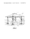
[0012] FIG. 1 is a perspective view of a canopy structure, according to one illustrated embodiment.
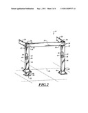
[0013] FIG. 2 is a partial perspective view of a support system of the canopy structure of FIG. 1.
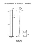
[0014] FIG. 3A is a cross-sectional side view of a support column and sheath of the canopy structure of FIG. 1, shown with a container and ballast material in an unassembled configuration.
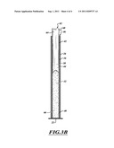
[0015] FIG. 3B is a cross-sectional side view of a support column and sheath of the canopy structure of FIG. 1, shown with a container and ballast material in an assembled configuration
DETAILED DESCRIPTION
[0016] In the following description, certain specific details are set forth in order to provide a thorough understanding of various disclosed embodiments. However, one skilled in the relevant art will recognize that embodiments may be practiced without one or more of these specific details, or with other methods, components, materials, etc. In other instances, well-known structures associated with canopy structures, such as pergolas, gazebos and the like have not been shown or described in detail to avoid unnecessarily obscuring descriptions of the embodiments.
[0017] Unless the context requires otherwise, throughout the specification and claims which follow, the word "comprise" and variations thereof, such as, "comprises" and "comprising" are to be construed in an open, inclusive sense, that is as "including, but not limited to."
[0018] Reference throughout this specification to "one embodiment" or "an embodiment" means that a particular feature, structure or characteristic described in connection with the embodiment is included in at least one embodiment. Thus, the appearances of the phrases "in one embodiment" or "in an embodiment" in various places throughout this specification are not necessarily all referring to the same embodiment. Furthermore, the particular features, structures, or characteristics may be combined in any suitable manner in one or more embodiments.
[0019] As used in this specification and the appended claims, the singular forms "a," "an," and "the" include plural referents unless the content clearly dictates otherwise. It should also be noted that the term "or" is generally employed in its broadest sense, that is as meaning "and/or" unless the content clearly dictates otherwise.
[0020] The headings and Abstract of the Disclosure provided herein are for convenience only and do not interpret the scope or meaning of the embodiments.
[0021] FIG. 1 illustrates a canopy structure 10 in the nature of a pergola according to one embodiment which includes a canopy 12 supported by a canopy support system 14. The canopy support system 14 includes a plurality of support columns 16 coupled together by a plurality of cross members 18, with each cross member 18 spanning between two adjacent support columns 16.
[0022] Each of the support columns 16 is an elongated load bearing generally rigid structural member coupled or formed integrally with a mounting foot 22. The support columns 16 collectively space the canopy 12 to a desired height above a foundation 24 on which the canopy structure 10 rests. The foundation 24 may be any suitable surface for supporting the canopy structure 10, such as, for example, a concrete patio, a wooden deck or a grass lawn.
[0023] The support columns 16 may be tubular and may be fabricated by various known manufacturing methods, such as, for example, rolling, forming, or extruding. Further, the support columns 16 may be fabricated into a variety of structural shapes (e.g., rectangular, cylindrical, trapezoidal, oval). The support columns 16 may comprise a metallic or non-metallic material. In one embodiment, the support columns 16 are aluminum rectangular tubes. Each support column 16 may be a unitary structure, or may be formed of multiple members or sections. For example, multiple sections may be telescoped together or may be attached end-to-end, for example via a friction or interference coupling, with or without a detent mechanism. Such may allow a height of the support columns 16 to be adjusted and/or may facilitate packaging.
[0024] Each support column 16 may be encased or covered by an outer structure or layer 26, such as, for example, a decorative sheath, a vinyl layer, an acrylic paint layer, a fabric layer or other material layer applied, adhered or otherwise attached to the support column 16. In one embodiment, the outer layer 26 is a woven sheath, such as, for example, a sheath of rattan wicker or the like.
[0025] The mounting foot 22 of each support column 16 may be concealed by a decorative foot cover 28. The foot cover 28 may include an exterior surface of the same material as the outer layer 26 to create a cohesive uniform external cover for the support columns 16. In alternate embodiments, the foot cover 28 may include an exterior surface of a different material than the outer layer 26.
[0026] A container 30 adapted to receive and retain ballast material 32 is received within each of the support columns 16 to provide adjustable counterbalancing of the canopy structure 10. More particularly, the container 30 may be filled to various levels with a ballast material 32 to selectively increase the weight of the support columns 16 and hence weight of the canopy structure 10. In some embodiments, the container 30 may be a flexible container, such as a plastic or fabric bag. In such embodiments, the ballast material 32 may fill the container 30 and conform to the internal profile of the support column 16. In this manner, the ballast material 32 may contribute to the rigidity of the support column 16 to reduce bending or twisting of the same when the support column 16 is subjected to wind or other external loads. In other embodiments, the container 30 may be rigid or semi-rigid. In such embodiments, the container 30 may contribute to the rigidity of the support column 16 to likewise reduce bending or twisting of the same when the support column 16 is subjected to wind or other external loads.
[0027] With reference to FIG. 2, each support column 16 is generally elongated having a lower end 40 and an upper end 42 separated by a central body portion having a longitudinally elongated cavity 44. The lower end 40 of each support column 16 is closed while the upper end 42 includes an opening 46 for receiving the container 30 and ballast material 32 in the longitudinal cavity 44.
[0028] The lower end 40 of each support column 16 includes a respective mounting foot 22 as described earlier. The mounting foot 22 may be a single flat sheet or plate of material that is the same material or a different material than that of the elongated structural member of the support column 16. The mounting foot 22 may also include apertures 48 for receiving nails, screws, anchors or other fasteners to optionally secure the support system 14 and hence canopy structure 10 to the foundation 24. The mounting foot 22 may have a base surface area that extends beyond a cross-sectional profile of its respective support column 16 to provide a suitable foot print for supporting the canopy structure 10 in a particularly stable upright position. In some embodiments, the mounting foot 22 may be formed integrally with the elongated structural member of the support column 16. In other embodiments, the mounting foot 22 may be attached or coupled to the elongated structural member, such as, for example, welding. In some embodiments, the support column 16 may not have a mounting foot 22 such that the elongated structural member of the support column 16 rests directly on the foundation 24 when the canopy structure 10 is erected.
[0029] The upper end 42 of each support column 16 is secured to an adjacent support column 16 by one of the plurality of elongated cross members 18. More particularly, a first end 50 of one of the cross members 18 is coupled to the upper end 42 of one of the support columns 16 while a second end 52 of the cross member 18 is coupled to the upper end 42 of another one of the support columns 16. The cross member 18 may be coupled to the support columns 16 via screws, bolts, nails, clips or other fasteners (not shown). As an example, in one embodiment, the cross members 18 are coupled to the support columns 16 via bolts inserted through mounting apertures 54.
[0030] As previously described, a container 30 adapted to receive and retain ballast material 32 is received within each of the support columns 16 to provide adjustable counterbalancing of the canopy structure 10. In some embodiments, the container 30 is removably insertable in the support column 16 such that the container 30 can be selectively loaded and unloaded from the support column 16. Accordingly, the support column 16 may be shipped or otherwise transported apart from the container 30. Ballast material 32 may be added or removed from the container 30 either with the container 30 separated from the support column 16 or with the container 30 positioned at least partially within the support column 16. In one embodiment, each support column 16 is adapted to receive a container 30 in the form of a flexible bag at an assembly location prior to receipt of the ballast material 32. A user is thus able to receive and manipulate support columns 16 during assembly without the counterbalance of the associated ballast material 32. The container 30 may be made of various materials, such as, for example, various plastic materials or fabric materials. The container 30 may be transparent (as illustrated) or may be opaque. The container 30 may be impermeable to water, sand or other ballast materials. In one embodiment, the container 30 is an elongated nylon bag.
[0031] Further details of assembling or erecting a portion of the canopy structure 10 will now be described with reference to FIGS. 3A and 3B. As illustrated in FIG. 3A, each support column 16 may be provided separate from a respective container 30 and associated ballast material 32. The ballast material 32 may be a variety of readily available materials, such as, for example, sand, gravel or water. Prior to assembly, the ballast material 32 may be held in a suitable receptacle, such as a wheel barrow, pail or bucket 60, prior to filling the container 30.
[0032] The support column 16 includes the opening 46 at the upper end 42 for receiving the container 30 within the longitudinal cavity 44. The lower end 40 of the support column 16 is substantially closed to prevent the container 30 from exiting or projecting beyond the support column 16 when placed therein. As illustrated in FIG. 3B, the container 30 may be inserted and positioned within the longitudinal cavity 44 of the support column 16 and subsequently filled with ballast material 32. More particularly, ballast material 32 may be fed through an inlet 62 at an upper end 64 of the container 30 such that the ballast material 32 settles at a lower end 66 of the container 30 and builds upwardly to fill at least a portion of the longitudinal cavity 44. As an example, the longitudinal cavity 44 may be filled to approximately half of a height of the support column 16, as illustrated in FIG. 3B, or may be filled to a height greater or less than that shown. A desired filling height is dependent on the cross sectional area of the longitudinal cavity 44, the characteristics of the canopy 12 that is supported and the expected loading conditions of a particular location where the canopy structure 10 is erected. For example, in areas known for high winds, a higher level of ballast material 32 may be desired to provide a particularly stable canopy structure 10.
[0033] Once the container 30 is filled to a desired level, the container 30 may be closed or sealed. Accordingly, in some embodiments, a fastener may be provided, such as, for example, a drawstring 68, a zipper, snaps or hook and loop fasteners to close or seal each of the containers 30. In embodiments wherein the containers 30 are flexible, portions of the container 30 that may extend beyond the upper end 42 of the support column 16 may be rolled, folded or tucked out of sight within the longitudinal cavity 44. The containers 30 may also be physically attached or secured to the support column 16 with fasteners, such as, for example, hooks, snaps or clips.
[0034] Although the support column 16 illustrated in FIGS. 3A and 3B is shown as standing vertical, it is appreciated that the support column 16 may be positioned at an inclined angle when filling the support column 16 with ballast material 32 and then tilted to the upright position for final assembly. In this manner, a user may gain access to the opening 46 of the support column 16 and inlet 62 of the container 30 from a standing position without the aid of a ladder or like device. Once erected, the support columns 16 provide counterbalancing such that the canopy structure 10 need not be secured or fastened to the foundation 24 on which it rests. The support columns 16, however, may be optionally secured or fastened to the foundation 24 for additional stability if desired.
[0035] Although the illustrated embodiment of the canopy structure 10 of FIG. 1 is shown as comprising four support columns 16 to support a canopy 12 having a generally rectangular periphery, it will be apparent to those skilled in the art that canopy structures 10 may include more or fewer support columns 16 and that the canopy 12 may vary in size and shape. Further, it is appreciated that embodiments of the canopy structures 10 described herein may omit the outer layer 26 surrounding each support column 16 and/or foot cover 28.
[0036] The various embodiments described above can be combined to provide further embodiments. All of the U.S. patents, U.S. patent application publications, U.S. patent applications, foreign patents, foreign patent applications and non-patent publications referred to in this specification and/or listed in the Application Data Sheet are incorporated herein by reference, in their entirety. Aspects of the embodiments can be modified, if necessary to employ concepts of the various patents, applications and publications to provide yet further embodiments.
[0037] These and other changes can be made to the embodiments in light of the above-detailed description. In general, in the following claims, the terms used should not be construed to limit the claims to the specific embodiments disclosed in the specification and the claims, but should be construed to include all possible embodiments along with the full scope of equivalents to which such claims are entitled. Accordingly, the claims are not limited by the disclosure.
User Contributions:
Comment about this patent or add new information about this topic:
Images included with this patent application:
 |  |
 |  |
| Similar patent applications: | |
| Date | Title |
|---|---|
| 2009-09-03 | Erectable canopy with reinforced roof structure |
| 2009-12-10 | Canopy and ground anchor structure |
| 2010-02-25 | Collapsible canopy support structure |
| 2010-02-25 | Erectable canopy with reinforced roof structure |
| 2008-10-30 | Method and system for encompassing a construction site structure |
| New patent applications in this class: | |
| Date | Title |
|---|---|
| 2022-05-05 | Solar protection or wind protection device |
| 2016-07-14 | Inflatable frame assembly |
| 2016-05-19 | Personal space creator |
| 2016-03-24 | Elevated hunting blind |
| 2015-11-19 | Tent system and methods |
| Top Inventors for class "Tent, canopy, umbrella, or cane" | |
| Rank | Inventor's name |
|---|---|
| 1 | Oliver Joen-An Ma |
| 2 | Mark C. Carter |
| 3 | Wanda Ying Li |
| 4 | Wanda Ying Li |
| 5 | Kendyl A. Roman |