Patent application title: METAL "SLIP CLIP" TO HOLD METAL STUDES IN TOP TRACK OF COMMERCIAL INTERIOR FRAMING
Inventors:
Mike A. Downey (Austin, TX, US)
IPC8 Class: AE04B138FI
USPC Class:
52698
Class name: Static structures (e.g., buildings) assembled in situ-type anchor or tie
Publication date: 2011-09-01
Patent application number: 20110209432
Abstract:
A "slip-clip" assembly that may be used to attach studs to top tracks in
metal frames to offset the effects of the upward or downward displacement
and that provide an expedient in the whole building process wherein the
studs are held in place by clip assemblies. The clip is rigidly attached
to a side leg of the top track. The clip has formed therein a recess
adapted to loosely engage a portion of a rim on an adjacent flange so
that the stud is loosely held in place with a slippage tolerance to
absorb vertical pressures on said frame stud.Claims:
1. An assembly for attaching a U-shaped stud perpendicularly received
within a channel of a U-shaped top track in a metal frame for supporting
walls in a building comprising: a U-shaped top track enclosing a channel;
a vertical U-shaped stud received in said top track channel perpendicular
to said top track; said U-shaped stud comprising a pair of vertical
flanges forming said U-shape, each of said pair of flanges having a
vertical peripheral inwardly extending rim; and at least one clip rigidly
attached to a side leg of said top track, said clip having formed therein
a recess adapted to loosely engage a portion of a rim on an adjacent
flange, wherein said stud is loosely held in place with a slippage
tolerance to absorb vertical pressures on said frame studs.
2. The assembly of claim 1, including a pair of said clips, wherein each of said clips is respectively rigidly attached to an opposing side leg of said top track, and loosely engages a portion of a rim on opposing flanges of said stud.
3. The assembly of claim 2, wherein said indentation on each of said clip recesses is V-shaped wherein each of said engaged rims slides against the recess V-shaped surface during slippage to absorb said vertical pressures.
4. A method of constructing a building using metal frames to support walls comprising: constructing a metal frame including: a U-shaped top track enclosing a channel; and a vertical U-shaped stud received in said top track channel perpendicular to said top track, said U-shaped stud comprising a pair of vertical flanges forming said U-shape, each of said pair of flanges having a vertical peripheral inwardly extending rim; rigidly attaching at least one clip to a side leg of the top track, said clip having formed therein a recess adapted to loosely engage a portion of a rim on an adjacent flange, wherein said stud is loosely held in place with a slippage tolerance to absorb vertical pressures on said frame studs resulting from transitory vertical loads during construction of the building support structure; and permitting said clip to remain attached to said top track after construction of the building support structure preventing further vertical pressures.
5. The method of constructing of claim 4, including temporarily rigidly attaching a pair of said clips, wherein each of said clips is respectively rigidly attached to an opposing side leg of said top track, and loosely engages a portion of a rim on opposing flanges of said stud.
6. The method of constructing of claim 5, wherein said indentation on each of said clip recesses is V-shaped, wherein each of said engaged rims slides against the recess V-shaped surface during slippage to absorb said vertical pressures.
7. The method of constructing of claim 6, further including the step of attaching a wall sheet to said metal frame.
8. An attachment assembly comprising: a horizontal U-shaped metal track enclosing a channel; a vertical U-shaped metal track received in said horizontal track channel perpendicular to said horizontal track; said vertical U-shaped track comprising a pair of vertical flanges forming said U-shape, each of said pair of flanges having a vertical peripheral inwardly extending rim; and at least one clip rigidly attached to a side leg of said horizontal track, said clip having formed therein a recess adapted to loosely engage a portion of a rim on an adjacent vertical flange, wherein said flange is loosely held in place with a slippage tolerance to absorb pressures on said vertical track.
9. The attachment assembly of claim 8, including a pair of said clips, wherein each of said clips is respectively rigidly attached to an opposing side leg of said horizontal track and loosely engages a portion of a rim on opposing flanges of said vertical track.
10. The assembly of claim 9, wherein said indentation on each of said clip recesses is V-shaped wherein each of said engaged rims slides against the recess V-shaped surface during slippage to absorb said pressures on said vertical track.
Description:
TECHNICAL FIELD
[0001] The present invention relates to metal framing that supports interior walls in buildings, and more particularly to a clip implementation to hold frame studs in place with respect to top tracks during construction.
BACKGROUND OF RELATED ART
[0002] Metal frames, including studs attached to top and bottom tracks, are conventionally used in commercial and industrial construction because such frames are fire resistant and do not warp. The top and bottom tracks in the frame are respectively attached to the ceiling and floor in the building structure. The metal studs in the frames that extend vertically between the top and bottom tracks are spaced between 16 and 24 inches apart. Wall hoard sheets, such as drywall, several feet in width are attached or hung on the frames. These metal frames are durable and strong enough to support the attached wall board. However, other than the wall board support, the metal frames do not perform any building support function. The building construction support for the building structure itself is provided by steel work or concrete.
[0003] Ideally, the metal frames would be installed after the building structure support in the form of steel or concrete is already in place, and there would no further problem with vertical pressures on the studs set in the tracks of the metal frames. However, based upon the scheduling of all of the contract and subcontract work involved in the construction of a building, it is frequently the case that the internal framing has to be installed, at various stages or building levels, before the building support structure is sufficiently complete and stabilized, so random vertical pressures from vertical transitory loads may result in upward or downward displacement that damage the frame studs.
SUMMARY OF THE PRESENT INVENTION
[0004] It has been found that there are two significant factors that may result in metal frame distortion and damage and, consequently, damage to the wall coverings, e.g. wall hoard. Both result from conventional attachments of stud flanges to the legs of the upper frame track of the metal frame. During building construction, the studs in the metal frame are permanently attached to the bottom track by suitable rigid attachments, e.g. screws. In addition, the studs are also rigidly attached to the top track by such screws that serve as temporary attachments in conventional frames.
[0005] It has been found that these conventional rigid screw attachments that were regarded as necessary to provide frame support for wall coverings, such as a wall board, cause construction delays. They are subject to the above-described damage to the frame due to random vertical pressures from vertical transitory loads, e.g. ceiling or roof loads that may result in upward or downward displacement that damages the frame studs due to the rigidity of the screw attachments. As a result, the framing and hanging of walls has to wait for weeks or longer in particular situations until the ceiling or roof is sufficiently completed and stabilized so as to eliminate such vertical loads.
[0006] In addition, it has been a practice in conventional metal framing to remove the temporary screws connecting the studs to the top tracks after hanging the walls and the completion of the building so as to permit some flexibility in the metal frames of completed buildings to absorb slight shifting of the building structures due to land movement. This need to remove the screw connections of the studs to top tracks has given rise to problems resulting from construction workers forgetting to remove such screw attachments.
[0007] The present invention resolves both of the above problems by providing a novel non-rigid attachment for studs to frame top tracks. The present invention provides a "slip-clip" assembly that may be used to attach studs to top tracks in metal frames to offset the effects of the upward or downward displacement, and that provide an expedient in the whole building process wherein the studs are held in place by the clip assembles of the present invention to absorb vertical pressures on said frame studs resulting from transitory vertical loads during construction of the building support structure. These clip assemblies need not be removed after the construction of building support structure prevents further vertical pressures, and the clip assemblies may remain in place as part of the permanent building structure.
[0008] In accordance with the present invention, an assembly is provided for attaching a U-shaped stud perpendicularly received within a channel of a U-shaped top track in a metal frame for supporting walls in a building. This assembly includes a U-shaped top track enclosing a channel and a vertical U-shaped stud received in the top track channel perpendicular to the top track. The U-shaped stud includes a pair of vertical flanges forming said U-shape with each of the pair of flanges having a vertical peripheral inwardly extending rim. There is at least one clip rigidly attached to a side leg of the top track, which clip has formed therein a recess adapted to loosely engage a portion of a rim on an adjacent flange so that the stud is loosely held in place with a slippage tolerance to absorb vertical pressures on said frame stud.
[0009] The assembly may be used as a means for maintaining studs in place within the frame during the construction process to absorb vertical pressures on the frame studs resulting from transitory vertical loads during construction. of the building support structure. The clip need not be removed after the construction of a building support structure that prevents further vertical pressures.
BRIEF DESCRIPTION OF THE DRAWINGS
[0010] The present invention will be better understood and its numerous objects and advantages will become more apparent to those skilled in the art by reference to the following drawings, in conjunction with the accompanying specification, in which:
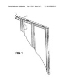
[0011] FIG. 1 is a diagrammatic view of an illustrative typical metal frame on which the clip assembly of the present invention may be used in the practice of this invention;
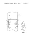
[0012] FIG. 2 is a diagrammatic horizontal section of a portion of a frame top track channel receiving a perpendicular vertical stud that is held in place by the clip assembly of the present invention;
[0013] FIG. 3 is a diagrammatic view of the clip member in the assembly;
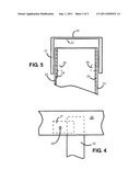
[0014] FIG. 4 is a simplified diagrammatic vertical section layout to show positioning of the clip with respect to the horizontal top track and a vertical stud received by the top track; and
[0015] FIG. 5 is a diagrammatic vertical section of the upper end of a vertical stud received in the top track of the frame.
DETAILED DESCRIPTION OF THE PREFERRED EMBODIMENT
[0016] FIG. 1 is a diagrammatic view of an illustrative typical metal frame on which the clip assembly on the present invention may be used in the practice of this invention. The frame includes a horizontal top track 10 and legs 11. Stud 12 with flanges 13 are received within the channel formed by legs 11 of track 10. In the metal frame structure, studs 12 are mounted within the top track channel.
[0017] The clip assembly of this invention will now be described with respect to FIG. 2, which is a diagrammatic horizontal section of a portion of a frame top track channel receiving a perpendicular vertical stud that is temporarily held in place by the clip assembly of the present invention. Legs 21 of horizontal top track 20 forms a channel within which flanges 23 of vertical stud 22 are received. Each of flanges 23 has an inwardly extending rim 24. Clips 25 have section 27 affixed to legs 21 of track 20 by screws 28 extending through clip sections 27. Clips 25 also have V shaped notches 26 that do not affix clips 25 to stud flanges 23. The notches 26 loosely engage rims 24 in stud flanges 23 to thereby loosely hold stud flanges 23 in place relative to top track 21 without creating a rigid attachment that could cause the stud 22 to bend or deform in response to vertical pressures on the metal frame.
[0018] FIG. 3 is a diagrammatic view of the clip member 25 in the assembly and the V notch 26 in arm 27 that is rigidly affixed to the top track leg.
[0019] FIG. 4 is a simplified diagrammatic side view layout to show positioning of the clip section 27 having a screw 28 attached to a leg of top track 20 and a vertical stud 22 received by the top track.
[0020] FIG. 5 is a diagrammatic vertical section of the upper end of a vertical stud received in the top track of the frame. FIG. 5 is a vertical section through the upper portion of the track/stud layout of FIG. 4. Upper track 20 has a pair of legs 21 for receiving adjacent pairs of flanges 23 having peripheral rims 24 associated with a pair of clips of which V notches 26 are shown. This pair of clip notches 26 respectively loosely engage flanges 23, and particularly rims 24 as shown in FIG. 2.
[0021] The following are some further details of the clip assembly described hereinabove. Clip 25 may be made from 16, 18, 20 or the like gauge metal. The V-shaped notch or recess that is bent stamped or rolled across the clip allows for the 90 degree return or rim 24 to fit within the V recess. The result is a capture of the stud flange 23 that is not rigid but which prevents upward or downward displacement.
[0022] As described hereinabove, the clip assembly of the present invention may be used in a building construction implementation wherein the slip-clip assemblies of the present invention rigidly attached the clip to the upper track of a frame while the stud flanges are loosely held by the V-notched clips as described. This provides a means for maintaining studs in place within the frame during the construction process to absorb vertical pressures on said frame studs resulting from transitory vertical loads during construction of the building support structure. The present clip assembly may be so effective in absorbing such vertical loads that wall sheets, such as dry wall, may be hung on the metal frames while the clip assemblies of this invention are in place. The clip assemblies need not be removed after the construction of a completed building support structure that prevents further vertical pressures.
[0023] Although certain preferred embodiments have been shown and described, it will be understood that many changes and modifications may be made therein without departing from the scope and intent of the appended claims.
User Contributions:
Comment about this patent or add new information about this topic:
| People who visited this patent also read: | |
| Patent application number | Title |
|---|---|
| 20160347223 | RECLINER ATTACHMENT BRACKET |
| 20160347222 | SUPPORT DEVICE FOR VEHICLE SEAT |
| 20160347221 | SEAT COVER AND VEHICLE SEAT |
| 20160347220 | Child Protection Liner |
| 20160347219 | VEHICLE SEAT |
Images included with this patent application:
 |  |
 |
| New patent applications in this class: | |
| Date | Title |
|---|---|
| 2017-08-17 | Connectors and methods of fabricating the same |
| 2016-12-29 | Fixture support for membrane roof |
| 2016-09-01 | Holeless curtain wall mullion connection |
| 2016-09-01 | Bracket assembly and method |
| 2016-07-14 | Non-penetrating roof-mounted support device |
| Top Inventors for class "Static structures (e.g., buildings)" | |
| Rank | Inventor's name |
|---|---|
| 1 | Darko Pervan |
| 2 | Gregory F. Jacobs |
| 3 | Husnu M. Kalkanoglu |
| 4 | Ronald P. Hohmann, Jr. |
| 5 | Mark Cappelle |