Patent application title: Multistage Production System and Method
Inventors:
Raymond Hofman (Midland, TX, US)
Raymond Hofman (Midland, TX, US)
IPC8 Class: AE21B3406FI
USPC Class:
166373
Class name: Wells processes operating valve, closure, or changeable restrictor in a well
Publication date: 2011-08-25
Patent application number: 20110203807
Abstract:
A system and method for more efficiently stimulating and producing from a
production string. The present invention comprises production tubing; at
least one selectively-openable valve assembly located inline with the
production tubing; and at least one flapper valve assembly located inline
with the production tubing. One flapper valve assembly is associated with
each selectively-openable valve assembly. The flapper valve assembly is
orientated to impede fluid flow in the downwell direction when closed.Claims:
1. A multistage hydrocarbon production system comprising: production
tubing; at least one selectively-openable valve assembly spaced along
said production tubing; at least one flapper valve assembly spaced along
said production tubing, there being one of said at least one flapper
valve assembly associated with each of said at least one
selectively-openable valve assembly; wherein each of said at least on
flapper valve assembly is oriented to impede fluid flow in the downwell
direction when closed.
2. A method of stimulating and producing from a hydrocarbon production zone, the method comprising the steps of: running a shifting string through a flapper valve assembly associated with a selectively-openable valve assembly, said shifting string adapted to actuated said flapper valve assembly and said selectively-openable valve assembly, said flapper valve assembly being orientated to impede fluid flow in the downwell direction when close; actuating said selectively-openable valve assembly to provide a flow path between said production tubing and said hydrocarbon production zone; displacing a fracing material through said selectively-openable valve assembly; displacing said shifting string to a position upwell from said flapper valve assembly without closing said selectively-openable valve assembly; and cause said flapper valve assembly to close.
Description:
CROSS-REFERENCES TO RELATED APPLICATIONS
[0001] This application claims the benefit of U.S. provisional application Ser. No. 61/305,325 filed Feb. 17, 2010 and entitled Multistage Production System and Method, which is incorporated by reference herein.
STATEMENT REGARDING FEDERALLY-SPONSORED RESEARCH OR DEVELOPMENT
[0002] Not applicable.
BACKGROUND OF THE INVENTION
[0003] 1. Field of the Invention
[0004] The present invention relates to a system for producing hydrocarbons from multiple stages in a hydrocarbon production well. More specifically, the present invention relates to a multistage production system that associates a flapper valve assembly with each production valve assembly in the multistage system.
[0005] 2. Description of the Related Art
[0006] During stimulation of a production zone (e.g., fracing) using a system incorporating multiple selectively-openable valve assemblies, the valve assembly furthest downwell is opened first with a shifting tool and a fracing material thereafter forced into the surrounding formation. The valve assembly is then closed and positive-pressure tested to insure system integrity before repeating the operation at the next upwell stage of the system. Positive pressure testing insures that the kinetic energy of the fracing material (i.e., fluid velocity) is concentrated at a single stage rather than egressing through another open (or partially open) stage. Focusing the kinetic energy of the fracing material at a single stage allows the fracing material to penetrate deeper into the formation, which results in greater effectiveness.
[0007] This process is repeated at each stage (i.e., through each valve) until the regions of the formation adjacent each of the stages have been stimulated. After this zonal stimulation, a shifting tool is again run through the production tubing and the valve assemblies are opened for production. This process, however, is time-consuming, and therefore expensive.
SUMMARY OF THE INVENTION
[0008] The present invention is a system and method for more efficiently and quickly producing from a production string. The present invention comprises production tubing; at least one selectively-openable valve assembly located inline with the production tubing; and at least one flapper valve assembly located inline with the production tubing. One flapper valve assembly is associated with each selectively-openable valve assembly. The flapper valve assembly is orientated to impede fluid flow in the downwell direction when closed.
BRIEF DESCRIPTION OF THE DRAWINGS
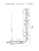
[0009] FIG. 1 is a partial sectional view of a well with a cemented open hole fracing system located in a producing zone.
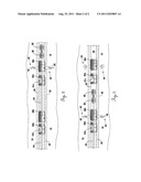
[0010] FIG. 2 is a partial sectional view of the production string of FIG. 1 showing a tooling string disposed through two sets of valve assemblies.
[0011] FIG. 3 is a partial sectional view of the production string of FIG. 1 showing a tooling string disposed through one valve assembly after having opened a another valve assembly.
DESCRIPTION OF THE INVENTION
[0012] FIG. 1 shows a multistage production system having the features of the present invention. A production well 10 is drilled in the earth 12 to a hydrocarbon production zone 14. A casing 16 provides structural stability to the vertical portion of the borehole and is held in place in the production well 10 by cement 18. A liner hanger 22 is located at the lower end of the casing 16. A length of production tubing 24 is connected to the liner hanger 22 and orientated to extend into the production zone 14 through the lateral portion of the borehole.
[0013] A number of selectively-openable sliding valve assemblies 28a-28c and flapper valve assemblies 30a-30c are positioned inline with the production tubing 24. Each of the flapper valve assemblies 30a-30c is associated with and positioned upwell from one of the corresponding sliding valve assembly 28a-28c--that is, the first flapper valve assembly 30a is associated with and positioned upwell from the first sliding valve assembly 28a, the second flapper valve assembly 30b is associated with and positioned upwell from the second sliding valve assembly 28b, and the third flapper valve assembly 30c is associated with and positioned upwell from the third sliding valve assembly 28c. Each of the flapper valve assemblies 30a-30c is orientated to block fluid flow in the downhole direction when closed. While the preferred embodiment discloses three sliding valve assemblies 28a-28c, more or fewer sliding valve assemblies may be used. The entire production tubing 24, sliding valve assemblies 28a-28c, and flapper valve assemblies 30a-30c are surrounded with cement 32. Each of the selectively-openable sliding valve assemblies 28a-28c is mechanically actuatable with a shifting tool. U.S. Pat. No. 7,267,172 (issued Sep. 10, 2007) to Hofman describes one such specific embodiment of a mechanically actuatable shifting tool.
[0014] FIG. 2 and FIG. 3 more clearly illustrate the portion of the production tubing 24 shown in FIG. 1 that includes the second and third sliding valve assemblies 28b, 28c and second and third flapper valve assemblies 30b, 30c. The flapper valve assemblies 30b, 30c each include a flapper plate 31b, 31c moveable between an opened and closed position. In FIG. 2, each of the flapper plates 31b, 31c is in an open position to allow flow through the production tubing 24. In FIG. 3, the second flapper plate 31b is open to permit downwell fluid flow and the third flapper plate 31c is closed to inhibit fluid flow in the downwell direction.
[0015] To initiate zonal stimulation, a shifting string 34 is run down the production tubing 24 with a first tool 36 adapted for actuating the flapper valve assemblies 30a-30c and a shifting tool 38 for opening the sliding valve assemblies 28a-28c. Prior to running the shifting string 34, each of the flapper valve assemblies 30a-30c is closed. The first tool 36 actuates the first flapper valve assembly 30a (see FIG. 1), after which the shifting string 34 may be run through the first sliding valve assembly 28a (see FIG. 1) and to the second flapper valve assembly 30b. Thereafter, the first tool 36 actuates the second flapper valve assembly 30b and third flapper valve assembly 30c in order that the shifting tool 38 may be caused to actuate the third sliding valve assembly 28c. (FIG. 2) The third sliding valve assembly 28c is then actuated to provide a flow path between the production tubing 24 and surrounding cement 32 and production zone 14. (FIG. 2) Fracing fluid 40 is then injected into the region 42 of the production zone 14 adjacent the third sliding valve assembly 28c.
[0016] After stimulation of the adjacent region 42 causing fracturing 44 of the production zone 14 proximal to the third valve assembly 28c, the shifting string 34 is positioned upwell to the second sliding valve assembly 28b. (FIG. 3) After sliding the shifting string 34 upwell from the portion of production tubing located downwell from the third flapper valve assembly 30c, the third flapper plate 31c closes to prevent fluid flow in a downwell direction past its position within the production tubing 24. The third sliding valve assembly 28c remains open to the surrounding production zone 14. This same process is repeated with the second sliding valve assembly 28b and first sliding valve assembly 28a respectively, such that after all zonal stimulation the sliding valve assemblies 28a-28c remain open and all flapper plates 31a-31c remain closed.
[0017] The present invention is described in terms of preferred embodiments in which a specific system and method are described. For example, while the present invention is described with respect to a cemented open lateral hole, the present invention can also be used in a cased vertical hole. Those skilled in the art will recognize that alternative embodiments of such system, and alternative applications of the method, can be used in carrying out the present invention. Other aspects and advantages of the present invention may be obtained from a study of this disclosure and the drawings, along with the appended claims. Moreover, the recited order of the steps of the method described herein is not meant to limit the order in which those steps may be performed.
User Contributions:
Comment about this patent or add new information about this topic:
| People who visited this patent also read: | |
| Patent application number | Title |
|---|---|
| 20130298788 | METHOD AND A MACHINE FOR DECORATING BOTTLES BY INDIRECT PAD PRINTING USING A SHELL |
| 20130298787 | DENSITY SYSTEM BYPASS FOR A ROUND BALER |
| 20130298786 | ACCUMULATOR SYSTEM FOR ROUND BALER BELT PRE-TENSION |
| 20130298785 | Nut Shell Removal System and Method |
| 20130298784 | ADDING AN ADDITIVE TO A PRODUCT SUITABLE FOR HUMAN CONSUMPTION |
Images included with this patent application:
 |  |
| Similar patent applications: | |
| Date | Title |
|---|---|
| 2011-06-09 | Multi-zone formation evaluation systems and methods |
| 2011-06-09 | Offshore drilling and production systems and methods |
| 2011-12-01 | Subsea production systems and methods |
| 2011-02-10 | Multiple well treatment fluid distribution and control system and method |
| 2009-11-19 | Plug protection system and method |
| New patent applications in this class: | |
| Date | Title |
|---|---|
| 2022-05-05 | Downhole inflow production restriction device |
| 2019-05-16 | Methods and systems for a bridge plug |
| 2017-08-17 | Sleeve fracturing assembly, device using the same and method for using the same |
| 2017-08-17 | Frac plug and methods of use |
| 2016-09-01 | Frangible plug to control flow through a completion |
| New patent applications from these inventors: | |
| Date | Title |
|---|---|
| 2015-05-14 | Downhole tools, system and methods of using |
| 2015-04-23 | Open hole fracing system |
| 2015-04-23 | Hydraulically-actuated explosive downhole tool |
| 2015-03-12 | Downhole tool with expandable seat |
| 2015-03-12 | Flow bypass device and method |
| Top Inventors for class "Wells" | |
| Rank | Inventor's name |
|---|---|
| 1 | Michael L. Fripp |
| 2 | Jean Marc Lopez |
| 3 | Michael H. Johnson |
| 4 | Jørgen Hallundbaek |
| 5 | Dennis P. Nguyen |