Patent application title: NOISE REDUCTION DEVICES FOR BLOWERS
Inventors:
Hideaki Takano (Anjo-Shi, JP)
Assignees:
MAKITA CORPORATION
IPC8 Class: AF04D2966FI
USPC Class:
415119
Class name: Rotary kinetic fluid motors or pumps with sound or vibratory wave absorbing or preventing means or arrangement
Publication date: 2011-08-18
Patent application number: 20110200426
Abstract:
A noise reduction device for a blower includes a noise reduction member.
The noise reduction member has a noise reduction chamber and a noise
reduction opening defined therein, so that a part of air flowing into,
through or out of the blower can enter the noise reduction chamber via
the noise reduction opening.Claims:
1. A blower comprising: a body housing having an air inlet portion and an
air outlet portion defining an air inlet passage and an air outlet
passage, respectively; and a rotary fan disposed within the body housing;
wherein the body housing includes a noise reduction portion having a
noise reduction chamber and a noise reduction hole; and wherein the noise
reduction chamber communicates with one of the air inlet passage and the
air outlet passage via the noise reduction hole.
2. The blower as in claim 1, wherein the noise reduction chamber is disposed in juxtaposed relationship with one of the air inlet passage and the air outlet passage.
3. The blower as in claim 1, wherein the noise reduction chamber communicates with the air outlet passage via the noise reduction hole.
4. The blower as in claim 1, wherein: the body housing is split into a left housing half and a right housing half joined together to form the body housing, the left housing half and the right housing half being positioned on a left side and a right side with respect to a direction of flow of air within one of the air inlet passage and the air outlet passage; and the noise reduction portion is split into a left portion and a right portion corresponding to the left housing half and the right housing half, respectively.
5. The blower as in claim 4, wherein: each of the left housing half and the right housing half is molded by resin, the left housing half has a first portion and a first wall integrated with the first portion; the right housing half has a second portion and a second wall integrated with the second portion; the air outlet passage of the air outlet portion is defined between the first portion and the second portion; and the noise reduction chamber and the noise reduction hole of the noise reduction portion are defined between the first wall and the second wait.
6. The blower as in claim 1, wherein a volume of the noise reduction chamber and a diameter of the noise reduction hole are determined based on the number of fins of the fan and the rotational speed of the fan.
7. A noise reduction device for a blower having a body housing and a rotary fan, the body housing having an air inlet portion and an air outlet portion defining an air inlet passage and an air outlet passage therein, respectively, and the rotary fan being disposed within the body housing; the noise reduction device comprising: a tubular member capable of mounting to one of the air inlet portion and the air outlet portion; wherein the tubular member defines therein an air blowing passage, a noise reduction chamber and a noise reduction hole; wherein the air blowing passage communicates with one of the air inlet passage and the air outlet passage when the tubular member is mounted to one of the air inlet portion and the air outlet portion; wherein the noise reduction chamber communicates with the air blowing passage via the noise reduction hole.
8. The noise reduction device as in claim 7, wherein the noise reduction chamber is disposed in juxtaposed relationship with the air blowing passage.
9. A noise reduction device for a blower, comprising: a noise reduction member having a noise reduction chamber and a noise reduction opening defined therein, so that a part of air flowing into, through or out of the blower can enter the noise reduction chamber via the noise reduction opening.
10. The noise reduction device as in claim 9, wherein the noise reduction member further includes an air blowing passage defined therein and communicating with the noise reduction chamber via the noise reduction opening, and air flowing into through or out of the blower can enter the air blowing passage.
11. The noise reduction device as in claim 10, wherein the blower has a rotary fan for producing a stream of air, and a volume of the noise reduction chamber and a diameter of the noise reduction hole are determined based on the number of fins of the fan and the rotational speed of the fan.
12. A blower comprising the noise reduction device as in claim 9, wherein: the blower includes a housing body having an air inlet portion and an air outlet portion defining an air inlet passage and an air outlet passage therein, respectively; the noise reduction member is formed integrally with the housing body; and the noise reduction opening communicates between the noise reduction chamber and one of the air inlet passage and the air outlet passage.
Description:
[0001] This application claims priority to Japanese patent application
serial number 2010-29802, the contents of which are incorporated herein
by reference.
[0002] The present invention relates to noise reduction devices for blowers that may be used for blowing wind to powder dust or the like generated, for example, at a construction site in order to gather the same or, conversely, for drawing and collecting the powder dust or the like.
DESCRIPTION OF THE RELATED ART
[0003] A known blower has a fan disposed within a body housing and rotatably driven by a motor for producing a flow of air into an air inlet portion and out of an air outlet portion of the body housing, so that air is blown out of the air outlet portion, while any dust is drawn into the air inlet portion. During the air being blown out, a noise (air blowing sound) may be produced by the air flowing into the air inlet portion and out of the air outlet portion in addition to a noise produced by the rotating motor. Therefore, it has been desired for reducing the air blowing sound.
[0004] Techniques relating to this kind of blowers are disclosed in Japanese Laid-Open Patent Publication Nos. 2001-50196 and 45-30389. Japanese Laid-Open Patent Publication No. 2001-50196 discloses a technique of removing static electricity that may be produced during the use of a blower. Japanese Laid-Open Patent Publication No. 45-30389 discloses a technique of reducing a noise. According to this noise reduction technique, a tubular muffler and a specific sound absorbing material each having a plurality of small holes are provided at each of an air inlet portion and an air outlet portion for reducing a noise within a specific frequency range.
[0005] However, in general, blowers are used as subsidiary devices at construction sites, and therefore, configuring a blower to have the muffler and the specific sound absorbing material as disclosed in Japanese Laid-Open Patent Publication No. 45-30389 leads to a complicated construction of the blower and increase of the manufacturing cost.
[0006] Therefore, there is a need in the art for a noise reduction device for a blower, which can reduce a noise without leading to a complicated construction.
SUMMARY OF THE INVENTION
[0007] According to the present teaching, a noise reduction device for a blower includes a noise reduction member. The noise reduction member has a noise reduction chamber and a noise reduction opening defined therein, so that a part of air flowing into, through or out of the blower can enter the noise reduction chamber via the noise reduction opening.
BRIEF DESCRIPTION OF THE DRAWINGS
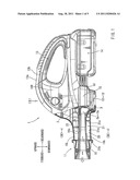
[0008] FIG. 1 is a side view of a blower according to a first example with a portion around an air outlet shown in a vertical sectional view;
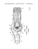
[0009] FIG. 2 is a plan view of the blower as viewed in a direction of arrow II in FIG. 1 with a portion around the air outlet shown in a horizontal sectional view;
[0010] FIG. 3 is a vertical sectional view taken along line III-III in FIG. 1 and showing a portion around the air outlet in a vertical sectional view.
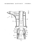
[0011] FIG. 4 is an enlarged side view of a noise reduction portion of the blower; and
[0012] FIG. 5 is a vertical sectional view of a noise reduction adaptor and an air outlet portion of a blower according to a second example.
DETAILED DESCRIPTION OF THE INVENTION
[0013] Each of the additional features and teachings disclosed above and below may be utilized separately or in conjunction with other features and teachings to provide improved sound reduction devices and blowers having such devices. Representative examples of the present invention, which examples utilize many of these additional features and teachings both separately and in conjunction with one another, will now be described in detail with reference to the attached drawings. This detailed description is merely intended to teach a person of skill in the art further details for practicing preferred aspects of the present teachings and is not intended to limit the scope of the invention. Only the claims define the scope of the claimed invention. Therefore, combinations of features and steps disclosed in the following detailed description may not be necessary to practice the invention in the broadest sense, and are instead taught merely to particularly describe representative examples of the invention. Moreover, various features of the representative examples and the dependent claims may be combined in ways that are not specifically enumerated in order to provide additional useful examples of the present teachings. Various examples will now be described with reference to the drawings.
[0014] In one example, a blower includes a body housing and a rotary fan. The body housing has an air inlet portion and an air outlet portion defining an air inlet passage and an air outlet passage, respectively. The rotary fan is disposed within the body housing. The body housing includes a noise reduction portion having a noise reduction chamber and a noise reduction hole. The noise reduction chamber communicates with one of the air inlet passage and the air outlet passage.
[0015] As the fan rotates, air flows into the air inlet passage of the air inlet portion and then flows out of the blower through the air outlet passage of the air outlet portion. Depending on the number of fins of the fan and the rotational speed of the fan, a variation in pressure (pulsation) may be produced in the stream of air, so that the air stream repeatedly alternates between a high pressure region and a low pressure region in the direction of flow of air through the inlet or outlet air passage. Therefore, when the air stream is produced, a part of air moves between the inlet or outlet air passage and the noise reduction chamber via the noise reduction hole in response to change of the pressure of the air stream. Then, a heat is produced due to friction between an edge of the noise reduction hole and the air passing through the noise reduction hole, so that sound energy of a part of the air stream is converted into frictional energy (heat energy), leading to decrease (deadening) of a noise produced by the air stream.
[0016] Thus, by communicating the air inlet or outlet passage with the noise reduction chamber via the noise reduction hole, the primary component of the air blowing sound can be reduced based on the principle of Helmholtz resonator. Because a muffler or a specific sound reduction material as required in the known art for reducing the noise is not necessary, it is possible to achieve effective noise reduction by a simple and low-cost construction.
[0017] Because it is possible to achieve effective noise reduction by a simple and low-cost construction, the blower of this example can be advantageously used for a blower that is used for performing a relatively light duty and ancillary work for blowing air or collecting dust.
[0018] The noise reduction chamber may be disposed in juxtaposed relationship with the air inlet or outlet passage. For example, the noise reduction chamber may communicate with the air outlet passage defined in the air outlet portion via the noise reduction hole.
[0019] The body housing may be split into a left housing half and a right housing half joined together to form the body housing. The left housing half and the right housing half are positioned on a left side and a right side with respect to a direction of flow of air within the air inlet or outlet passage. In this connection, the noise reduction portion may be split into a left portion and a right portion corresponding to the left housing half and the right housing half, respectively. With this arrangement, it is possible to easily manufacture the body housing that has the noise reduction portion.
[0020] Each of the left housing half and the right housing half may be molded by resin. The left housing half may have a first portion and a first wall integrated with the first portion. The right housing half may have a second portion and a second wall integrated with the second portion. The air outlet passage of the air outlet portion may be defined between the first portion and the second portion. The noise reduction chamber and the noise reduction hole of the noise reduction portion may be defined between the first wall and the second wall. With this arrangement, it is possible to form the noise reduction chamber and the noise reduction hole by a simple manufacturing process or a simple assembling process. Therefore, the manufacturing cost can be further reduced.
[0021] A volume of the noise reduction chamber and a diameter of the noise reduction hole may be determined based on the number of fins of the fan and the rotational speed of the fan, so that it is possible to thither effectively achieve reduction of the noise.
[0022] In another example, a noise reduction device for a blower is provided. The noise reduction device includes a tubular member capable of mounting to one of the air inlet portion and the air outlet portion. The tubular member defines therein an air blowing passage, a noise reduction chamber and a noise reduction hole. The air blowing passage communicates with the air inlet or outlet passage when the tubular member is mounted to one of the air inlet portion and the air outlet portion. The noise reduction chamber communicates with the air blowing passage via the noise reduction hole. The noise reduction chamber may be disposed in juxtaposed relationship with the air blowing passage.
[0023] Also, with the adaptor constructed in this way, it is possible to achieve the same noise reduction effect as the noise reduction portion formed on the blower. In addition, the adaptor is simple in construction and can be manufactured at a lower cost.
[0024] Examples will be now described with reference to FIGS. 1 to 5. Referring to FIGS. 1 to 4, there is shown a blower 1 according to a first example. The blower 1 has an electric motor 2 that serves as a drive source and is disposed within a body housing 10. In this example, the motor 2 is a DC motor that receives a supply of electric power from a battery pack 14. An air outlet portion 11 has a tubular configuration and is integrally formed with the front portion of the body housing 10. An air inlet portion 12 includes an air inlet passage. In this example, the air inlet passage is a plurality of slit-like air inlet openings fanned in the lower portion of the body housing 10. A loop-shaped handle 13 is disposed at the rear portion of the body housing 10, and the battery pack 14 serving as a DC power source is mounted to the lower portion of the handle 13. The electric power of the battery pack 14 is supplied to the motor 14 for rotating the same. The battery pack 14 has rechargeable batteries and can be removed from the handle 13. A battery charger prepared separately from the battery pack 14 can recharge the batteries, so that the battery pack 14 can be repeatedly used. A start switch 13a and a stop switch 13b each configured as a push button switch are mounted to the upper portion of the handle 13. The motor 2 starts when the start switch 13a is pushed, while the motor 2 stops when the stop switch 13b is pushed.
[0025] A fan 3 is mounted to an output shaft of the motor 2. In this example, a centrifugal fan is used for the fan 3. The fan 3 has nine fins 3a. As shown in FIGS. 2 and 3, a fan case 15 is provided at substantially the central portion of the body housing 10 and is configured like a circular disk extending laterally therefrom. When the motor 2 starts to rotate the fan 3, an external air is drawn into the fan case 15 from the air inlet portion 12 and is then blown in a radial direction along the fins 3a to collide with the inner surface of the fan case 15. As a result, a stream of air circulating in a counterclockwise direction as viewed in FIG. 2 is produced and the streaming air is thereafter blown out of the air outlet portion 11.
[0026] A noise reduction portion 20 serving as a noise reduction device of the first example is disposed at the air outlet portion 11. The details of the noise reduction portion 20 be described later.
[0027] The body housing 10 is made of resin and has a split-half construction having a left housing half 10L and a right housing half 10R molded separately from each other. The left and right housing halves 10L and 10R are joined together after they are brought to abut to each other. The left housing half 10L and the right housing half 10R are positioned on the left side and the right side, respectively, with respect to a direction of flow of air indicated by an outline arrow in FIG. 1. FIGS. 2 and 3 show a mating plane 3 where the left and right housing halves 10L and 10R abut to each other. The left and right housing halves 10L and 10R are configured to be symmetrical with each other except for portions forming the fan case 15. Each of the air inlet portion 11, the air outlet portion 12, and the handle 13 of the body housing 10 is split into two parts that are formed integrally with the left and right housing halves 10L and 10R, respectively.
[0028] The air outlet portion 11 formed integrally with the front portion of the body housing 10 has a substantially cylindrical tubular shape and has a configuration split into a left half and a right half according to the split-half configuration of the housing 10. The noise reduction portion 20 provided at the air outlet portion 11 also has a configuration split into a left half and a right half. Therefore, the air outlet portion 11 and the noise reduction portion 20 are assembled simultaneously with assembling the body housing 10 by bringing the left and right housing halves 10L and 10R to abut to each other and joining together.
[0029] An upper wall 16a and a lower wall 16b are formed integrally with the air outlet portion 11. An air blowing passage 16 serving as an air outlet passage of the blower 1 is defined between the upper and lower walls 16a and 16b. An upstream side of the air blowing passage 16 communicates within inside of the fan case 15. The air of the stream produced by the rotation of the fan 3 flows through the air blowing passage 16 and is thereafter blown out of the air outlet portion 11. In order to produce a desired stream of blowing air, a nozzle (not shown) may be attached to the air outlet portion 11, so that air may flow out of an end portion of the nozzle.
[0030] FIG. 4 shows the details of the noise reduction portion 20. The noise reduction portion 20 is disposed on the lower side of the air blowing passage 16 and has a noise reduction chamber 21 and a noise reduction hole 22. The noise reduction chamber 21 is defined by the lower wall 16b, an arc-shaped bottom wall 21a formed integrally with a lower portion of the lower wall 16b, a front wall 21b and a rear wall 21c. The noise reduction hole 22 is formed in the lower wall 16b. The noise reduction chamber 21 communicates with the air blowing passage 16 via the noise reduction hole 22. The noise reduction chamber 21 is sealed not to communicate with any other spaces, except for the noise reduction hole 22.
[0031] Each of the upper wall 16a, the lower wall 16b, the front wall 21b, the rear wall 21c and the noise reduction hole 22 has a configuration split into a left half and a right half corresponding to the split-half configuration of the body housing 10. Therefore, in order to assemble the upper wall 16a, the lower wall 16b, the front wall 21b, the rear wall 21c and the noise reduction hale 22, left and right halves corresponding to these parts and integrally molded with portions of the left and right housing halves 10L and 10R forming the air outlet portion 11 are abutted to and joined to each other. Hence, assembling the body housing 10 by joining the left and right housing halves 10L and 10R together leads to simultaneously assemble the noise reduction chamber 21 and the noise reduction hole 22 by joining the corresponding left and right halves together. As a result, the noise reduction portion 20 can be formed without need of a specific additional operation.
[0032] The operation of the noise reduction portion 20 constructed as described above will now be described. A variation (pulsation) in pressure depending on the number of fins 3a of the fan 3 may be produced in the air flowing within the air blowing passage 16. Due to the pressure variation of air, movement (flow) of air between the air blowing passage 16 and the noise reduction chamber 21 occurs in accordance of the principle of a Helmholtz resonator. When such movement of air between the air blowing passage 16 and the noise reduction chamber 21 occurs, a heat may be produced by a friction between an edge portion of the noise reduction hole 22 and the air flowing along the edge portion. This generation of the frictional heat means that sound energy of the air passing through the air blowing passage 16 is converted into heat energy, so that an air blowing sound is reduced accordingly.
[0033] The volume of the noise reduction chamber 21 and the diameter of the noise reduction hole 22 are suitably set according to the frequency of the air blowing sound, which may vary with the number of fins 3a of the fan 3, the rotational speed of the fan 3, or any other factors. More specifically, in this example, the rotational speed of the fan 3 having the nine fins 3a is set to 16,000 rpm to produce an air blowing sound having a frequency of about 2.4 kHz. On the other hand, the volume of the noise reduction chamber 21 is set to be 14,100 mm3, the diameter of the noise reduction hole 22 is set to be 25 mm, and a thickness t of the lower wall 16b or the depth (length) of the noise reduction hole 22 is set to be 1.5 mm. The inventor of the present invention confirmed through experiments that setting the sizes of these parts in this way can provide an excellent noise reduction effect. In the case of this example, the level of the primary component of the noise produced by the air blown through the air outlet portion 11 was reduced by about 5 to 10 dB than that of the noise produced by air blown through an air outlet of a known blower having no specific sound reduction device. Therefore, no high-pitched and unpleasant noise was generated, and a quality of the sound could be improved. As a result, it is possible to improve the operation performance of the blower 1.
[0034] According to the blower 1 of the first example constructed as described above, it is possible to reduce the air blowing sound by the sound reduction portion 20 provided at the air outlet portion 11. The sound reduction portion 20 includes the noise reduction chamber 21 juxtaposed with the air blowing passage 16 and further includes the noise reduction hole 22 communicating between the noise reduction chamber 21 and the air blowing passage 16. Because the noise reduction chamber 21 and the noise reduction hole 22 are formed by parts that are integral with the body housing 10 and each has a configuration split into a left half and a right half, they can be assembled simultaneously with assembling the body housing 10. The left and right halves forming the noise reduction chamber 21 and the noise reduction hole 22 can be molded together with the corresponding housing halves 10L and 10R, for example, by using molds slightly modified from those used for molding the housing halves 10L and 10R that do not include the noise reduction chamber 21 and the noise reduction hole 22. Therefore, the noise reduction portion 20 can be easily and economically manufactured in comparison with a construction using a muffler or a specific noise reduction material.
[0035] The above first example can be modified in various ways. For example, although the air outlet portion 11 having the noise reduction portion 20 is formed integrally with the body housing 10 having a split-half construction in the first example, the noise reduction portion 20 may be formed separately from the body housing 10. In such a case, a plurality of noise reduction devices each having a noise reduction member corresponding to the noise reduction portion 20 may be prepared for exchangeably mounting to an air outlet portion or an air inlet portion of a body housing of a blower that does not have the noise reduction portion. In addition, the noise reduction devices prepared in this way may be configured as adaptors that can be removably mounted to existing blowers having no specific noise reduction devices.
[0036] A noise reduction device prepared as an adopter for mounting to a blower will be hereinafter described as a second example with reference to FIG. 5. The basic construction of the blower 1 of the second example is the same as that of the blower 1 shown in FIGS. 1 to 4. However, the blower 1 of the second example is different from the blower 1 shown in FIGS. 1 to 4 in that the air outlet portion 17 has no noise reduction portion 20. Therefore, only the front portion of the air outlet portion 17 is shown in FIG. 5. A noise reduction device 30 according to the second example shown in FIG. 5 can be detachably mounted to the air outlet 17.
[0037] Referring to FIG. 5, the noise reduction device 30 has a noise reduction member 35 having a substantially tubular shape and made of resin. Similar to the body housing 10, the noise reduction member 35 has a split-half construction similar to that of the body housing 10. An upper wall 31a and a lower wall 31b are formed within the noise reduction member 35 and define an air blowing passage 31 therebetween. When the noise reduction device 30 is mounted to the air outlet portion 17 of the blower 1, the air blowing passage 31 communicates with the air blowing passage 16 of the air outlet portion 17.
[0038] The noise reduction member 35 has two lower and upper noise reduction portions 32 and 33. The lower noise reduction portion 32 has a noise reduction chamber 32a disposed along a lower wall 31b and a noise reduction hole 32b formed in the lower wall 31b. The upper noise reduction portion 33 has a noise reduction chamber 33a disposed along an upper wall 31a and a noise reduction hole 33b formed in the upper wall 31a. The lower noise reduction chamber 32a and the upper noise reduction chamber 33a are sealed from the outside except for the noise reduction hole 32b and the noise reduction hole 33b, respectively. The diameters of the lower and upper noise reduction holes 32b and 33b are suitably determined based on a frequency of the air blowing sound, which may depend on the number of fins 3a of the fan 3, the rotational speed of the fan 3 or any other factors.
[0039] With the noise reduction device 30 configured in this way, it is possible to achieve substantially the sane advantages as the first example. In addition, because the noise reduction device 30 can be detachably mounted to the air outlet portion 17, it is possible to provide a sound reduction effect to an existing blower that does not have a specific noise reduction function. Thus, a noise reduction function can be given to the existing blower by simply mounting the noise reduction device 30 thereto.
[0040] The first and second examples can be further modified. For example, the volume of the noise reduction chamber 21 (32a, 33) and the diameter of the noise reduction hole 22 (32b, 33b) can be suitably determined based on the frequency of the air blowing sound, which may vary with change of the number of fins of the fan, the rotational speed of the fan or any other factors.
[0041] Further, a plurality of noise reduction holes may be provided for one or each noise reduction chamber, and it may be possible to provide a plurality of noise reduction chambers arranged along the direction of flow of the blowing air.
[0042] Furthermore, although the blower 1 in the above examples is driven by the motor 2 that receives the supply of electric power from the battery pack 14, the DC motor 2 may be replaced with an AC motor that receives a supply of an AC power from a commercially available AC power source. In other words, the blower 1 may be configured as an AC blower. Alternatively, the DC motor 2 may be replaced with an internal combustion engine to configure the blower as an engine blower.
[0043] Further, although the blower 1 discharges air from the air outlet portion 11 (17) or the noise reduction adaptor 30 in the above examples, it may be possible to draw air from the air outlet portion 11 (17) or the noise reduction device 30 for collecting dust or the like by rotating the fan 3 in a reverse direction. Thus, the noise reduction portion 20 (the noise reduction device 30) can be applied to one or both of the air outlet portion and the air inlet portion. In brief, the noise reduction portion 20 (the noise reduction device 30) can be used at any place where the air pressure varies or fluctuates depending on the number of fans or other factors.
User Contributions:
Comment about this patent or add new information about this topic:
Images included with this patent application:
 |  |
 |  |
 |
| Similar patent applications: | |
| Date | Title |
|---|---|
| 2010-11-04 | Noise attenuation device for a centrifugal compressor discharge or suction nozzle |
| 2011-05-19 | Oscillation reducing suspension device for a fan motor of a combustion-powered tool |
| 2008-08-28 | Noise reduction assembly for aircraft turbojet |
| 2009-11-19 | Vibration-absorbing device for blower motors |
| 2009-07-02 | Methods and apparatus for error reduction in rotor loading measurments |
| New patent applications in this class: | |
| Date | Title |
|---|---|
| 2017-08-17 | Fan and air-conditioning apparatus using the same |
| 2016-12-29 | Turbine exhaust cylinder strut strip for shock induced oscillation control |
| 2016-07-14 | Suction device with sound mirror device |
| 2016-07-07 | Centrifugal fan, and fan equipped with sound-muffling box and using centrifugal fan |
| 2016-06-30 | Flexibly damped mounting assemblies for power gear box transmissions in geared aircraft engine architectures |
| New patent applications from these inventors: | |
| Date | Title |
|---|---|
| 2022-07-28 | Electric powered work machine and method of controlling noise generated by electric powered work machine |
| 2014-05-29 | Power tool |
| Top Inventors for class "Rotary kinetic fluid motors or pumps" | |
| Rank | Inventor's name |
|---|---|
| 1 | Gabriel L. Suciu |
| 2 | Frederick M. Schwarz |
| 3 | United Technologies Corporation |
| 4 | Brian D. Merry |
| 5 | Craig M. Beers |