Patent application title: Combustion exhaust energy conversion system
Inventors:
Ian P. Speers (Wellesley, MA, US)
IPC8 Class: AF01D1512FI
USPC Class:
4151242
Class name: Rotary kinetic fluid motors or pumps including shaft transmission train, brake, clutch, or attendant actuated drive means shaft transmission train having flexible means or coupling
Publication date: 2011-08-04
Patent application number: 20110188998
Abstract:
An energy conversion system that comprises a turbine rotor mounted inside
an exhaust stack or chimney. The turbine is connected to a generator with
a flexible drive shaft.Claims:
1. An energy conversion system comprising: a section of pipe; a turbine
rotor mounted in said section of pipe; a flexible drive shaft connected
to axis of said turbine rotor a generator coupled to said turbine rotor
by said flexible drive shaft a battery pack electrically connected to
said generator a plurality of turbine blades attached to said turbine
rotor.Description:
BACKGROUND OF THE INVENTION
[0001] 1. Field of the Invention
[0002] The present invention relates to a system to generate electricity from the naturally drafted flow of air in exhaust systems of residences and industrial facilities.
[0003] 2. Description of the Prior Art
[0004] References Cited
TABLE-US-00001 U.S. Pat. Documents RE6998 Jun. 11, 1876 Oberdorff 1,469,064 Sep. 25, 1923 Zucker 1,534,799 Apr. 21, 1925 Maine 1,833,666 Nov. 24, 1931 Watson et al. 2,836,398 May 27, 1958 Linderoth 6,765,308 Jul. 20, 2004 Kazanjian et al.
[0005] The use of wind mills or wind wheels or wind engines to convert the kinetic energy of wind into electricity via generators is well known in the prior art. For example, U.S. Pat. No. RE6998 to Oberdorff in 1876 discloses a primitive wind mill. Numerous improvements have been disclosed over the years, including U.S. Pat. Nos. 1,469,064 to Zucker and 1,534,799 to Maine.
[0006] It was long been realized that the combustion process creates byproducts that are dangerous to health and therefore need to be vented via exhaust stacks and chimneys. It was also long been recognized that these exhausts from combustion lead to tremendous energy losses. As an example, in the Process Heating Assessment and Survey Tool provided by the US Department of Energy, a typical industrial process heating system uses gross fuel input of 14.1 million Btu/hour and while generating useful output of 6.1 million Btu/hour, it loses 5.7 million Btu/hour in flue gas losses. Many inventors have sought to capture some of the heat lost in the exhaust of combustion processes through some sort of heat exchanger which uses the heat in the exhaust to warm air entering the combustion process. For example, U.S. Pat. No. 1,833,666 to Watson et al. and U.S. Pat. No. 2,836,398 to Linderoth provide examples of such valuable inventions.
[0007] While the above-described devices fulfill their respective, particular objectives and requirements, the aforementioned patents do not describe a system that generates energy by harnessing the kinetic energy from exhaust gases from various types of combustion devices such as boilers and furnaces. In fact, the closest invention is described in U.S. Pat. No. 6,765,308 to Kazanjian et al. which describes a hydro-energy conversion system that uses a hydraulic turbine rotor to capture energy from the flow of water in a water system and briefly mentions its possible applicability to waste water.
SUMMARY OF THE INVENTION
[0008] In view of the foregoing disadvantages inherent in the known types of turbines and electrical generators now present in the prior art, the present invention provides an improved energy conservation and conversion system, and overcomes the above-mentioned disadvantages and drawbacks of the prior art. As such, the general purpose of the present invention, which will be described subsequently in greater detail, is to provide a new and improved energy conversion system and method which has all the advantages of the prior art mentioned heretofore and many novel features that result in an energy conversion system which is not anticipated, rendered obvious, suggested, or even implied by the prior art, either alone or in any combination thereof.
[0009] To attain this, the present invention essentially comprises a turbine rotor that is connected to a generator with the use of a flexible drive shaft. It is likely that the turbine rotor would be mounted in a self-contained section of exhaust pipe to facilitate its integration with an existing or new exhaust system.
[0010] There has thus been outlined, rather broadly, the more important features of the invention in order that the detailed description thereof that follows may be better understood and in order that the present contribution to the art may be better appreciated.
[0011] The invention may also include turbine bushings, turbine drive shaft, thrust washers, air seals, turbine pulley, generator pulley, belt, battery pack, ac/dc power inverter, charge controller and vent. There are, of course, additional features of the invention that will be described hereinafter and which will form the subject matter of the claims attached.
[0012] Numerous objects, features and advantages of the present invention will be readily apparent to those of ordinary skill in the art upon a reading of the following detailed description of presently preferred, but nonetheless illustrative, embodiments of the present invention when taken in conjunction with the accompanying drawings. In this respect, before explaining the current embodiment of the invention in detail, it is to be understood that the invention is not limited in its application to the details of construction and to the arrangements of the components set forth in the following description or illustrated in the drawings. The invention is capable of other embodiments and of being practiced and carried out in various ways. Also, it is to be understood that the phraseology and terminology employed herein are for the purpose of descriptions and should not be regarded as limiting.
[0013] As such, those skilled in the art will appreciate that the conception, upon which this disclosure is based, may readily be utilized as a basis for the designing of other structures, methods and systems for carrying out the several purposes of the present invention. It is important, therefore, that the claims be regarded as including such equivalent constructions insofar as they do not depart from the spirit and scope of the present invention.
[0014] It is therefore an object of the present invention to provide a new and improved energy conversion system that has all of the advantages of the prior art turbines and electrical generators and none of the disadvantages.
[0015] It is another object of the present invention to provide a new and improved energy conversion system that may be easily and efficiently manufactured and marketed.
[0016] An even further object of the present invention is to provide a new and improved energy conversion system that has a low cost of manufacture with regard to both materials and labor, and which accordingly is then susceptible of low prices of sale to the consuming public, thereby making such energy conversion system economically available to the buying public.
[0017] Still another object of the present invention is to provide a new energy conversion system that provides in the apparatuses and methods of the prior art some of the advantages thereof, while simultaneously overcoming some of the disadvantages normally associated therewith.
[0018] Even still another object of the present invention is to provide an energy conversion system relevant to large-scale industrial use as well as small-scale residential use.
[0019] These together with other objects of the invention, along with the various features of novelty that characterize the invention, are pointed out with particularity in the claims annexed to and forming a part of this disclosure. For a better understanding of the invention, its operating advantages and the specific objects attained by its uses, reference should be had to the accompanying drawings and descriptive matter in which there are illustrated preferred embodiments of the invention.
BRIEF DESCRIPTION OF THE INVENTION
[0020] The invention will be better understood and objects other than those set forth above will become apparent when consideration is given to the following detailed description thereof. Such description makes reference to the annexed drawings wherein:
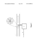
[0021] FIG. 1 is a plan view of the preferred embodiment of the energy conversion system constructed in accordance with the principles of the present invention.
[0022] In FIG. 1, the energy conversion system comprises a turbine 3 mounted inside a short section of pipe 2 that can be connected to an existing or new exhaust stack 1. A flexible drive shaft 4 connected to the axis of the turbine 3 exits the side wall of the pipe section 2 and connects to a generator 5. The system is incorporated into the exhaust pipe 1 of a combustion device such as a boiler or furnace. When exhaust flows through the exhaust pipe, the turbine blade turns. This kinetic energy is conveyed to the generator by the flexible drive shaft. The generator generates electrical energy that then flows to power electrical devices or storage units 6.
[0023] While a preferred embodiment of the energy conversion system has been described in detail, it should be apparent that modifications and variations thereto are possible, all of which fall within the true spirit and scope of the invention. With respect to the above description then, it is to be realized that the optimum dimensional relationships for the parts of the invention, to include variations in size, materials, shape, form, function and manner of operation, assembly and use, are deemed readily apparent and obvious to one skilled in the art, and all equivalent relationships to those illustrated in the drawings and described in the specification are intended to be encompassed by the present invention. For example, the turbine could be connected to the generator by means other than the flexible drive shaft described.
[0024] Therefore, the foregoing is considered as illustrative only of the principles of the invention. Further, since numerous modifications and changes will readily occur to those skilled in the art, it is not desired to limit the invention to the exact construction and operation shown and described, and accordingly, all suitable modifications and equivalents may be resorted to, falling within the scope of the invention.
DESCRIPTION OF THE PREFERRED EMBODIMENT
[0025] Referring now to the drawing, FIG. 1, a preferred embodiment of the present invention is shown and generally designated. It should be apparent that modifications and variations thereto are possible, all of which fall within the true spirit and scope of the invention. With respect to the above description then, it is to be realized that the optimum dimensional relationships for the parts of the invention, to include variations in size, materials, shape, form, function and manner of operation, assembly and use, are deemed readily apparent and obvious to one skilled in the art, and all equivalent relationships to those illustrated in the drawing and described in the specification are intended to be encompassed by the present invention. For example, although a flexible drive shaft is envisioned as connecting the turbine blade to the generator, many other connections, such as gears and pulleys with belts, are possible and covered by the present invention.
[0026] Therefore, the foregoing is considered as illustrative only of the principles of the invention. Further, since numerous modifications and changes will readily occur to those skilled in the art, it is not desired to limit the invention to the exact construction and operation shown and described, and accordingly, all suitable modifications and equivalents may be resorted to, falling within the scope of the invention.
User Contributions:
Comment about this patent or add new information about this topic:
| People who visited this patent also read: | |
| Patent application number | Title |
|---|---|
| 20140143343 | BIFURCATED CONFERENCING FUNCTIONS |
| 20140143342 | VISIBILITY INSPECTOR IN SOCIAL NETWORKS |
| 20140143341 | SYSTEM AND METHOD FOR NOTIFYING A USER OF PEOPLE, PLACES OR THINGS HAVING ATTRIBUTES MATCHING A USER'S STATED PREFERENCE |
| 20140143340 | METHODS AND SYSTEMS FOR PAUSING AND RESUMING A MEETING SESSION |
| 20140143339 | METHOD, APPARATUS, AND SYSTEM FOR RESOURCE SHARING |
Images included with this patent application:
 |
| New patent applications in this class: | |
| Date | Title |
|---|---|
| 2016-07-07 | Axial blower vacuum |
| 2016-06-16 | Centrifugal compressor |
| 2016-05-12 | Centrifugal compressor |
| 2015-11-12 | Stub shaft |
| 2015-02-05 | Joint |
| Top Inventors for class "Rotary kinetic fluid motors or pumps" | |
| Rank | Inventor's name |
|---|---|
| 1 | Gabriel L. Suciu |
| 2 | Frederick M. Schwarz |
| 3 | United Technologies Corporation |
| 4 | Brian D. Merry |
| 5 | Craig M. Beers |