Patent application title: Device For Concentration Of Material On A Water Surface And Use Of The Device
Inventors:
Steinar Heimtun (Fevik, NO)
Ole Kristoffer Torsvik (Spangereid, NO)
Tore Halvorsen (Fevik, NO)
IPC8 Class: AE02B1504FI
USPC Class:
405 63
Class name: Fluid control, treatment, or containment floatable matter containment floating barrier
Publication date: 2011-08-04
Patent application number: 20110188934
Abstract:
A device for concentration of material on a water surface, wherein the
device forms a front opening and is provided with buoyancy bodies and
guide elements structured for guiding the material towards a collection
portion, wherein the device is structured for admitting water through the
device in the flow direction of the water, and wherein the device, in a
portion thereof, is provided with at least two consecutive guide elements
in the flow direction of the water.Claims:
1. A device for concentration of material on a water surface, said device
comprising: a front opening; buoyancy bodies; guide elements structured
for guiding the material towards a collection portion; the device being
structured for admitting water through the device in a flow direction of
the water; and at least two consecutive guide elements in the flow
direction of the water being provided in a portion of the device.
2. The device according to claim 1, wherein said guide elements are fixed to a form element.
3. The device according to claim 2, wherein said form element includes a net.
4. The device according to claim 2, wherein said form element is of a triangular shape.
5. The device according to claim 1, wherein said guide elements further include a buoyancy body, a skirt and a weight rope.
6. The device according to claim 1, wherein a longitudinal direction of said guide elements form an angle of between 0.degree. and 90.degree. with respect to a width direction of said front opening.
7. The device according to claim 1, wherein at least two guide elements are substantially parallel.
8. The device according to claim 1, wherein said collection portion of said device includes a mid-portion of the device.
9. The device according to claim 1, wherein two and two collection ends of said guide elements form an opening in a mid-portion of said device.
10. The device according to claim 1, wherein said device is provided with spacers structured for towing behind a vessel.
11. The device according to claim 10, wherein said spacers includes a door.
12. A method of concentrating material located on or directly below a water surface, said method including the following step: guiding concentrated material through a device having a front opening, buoyancy bodies and guide elements structured for guiding the material towards a collection point of the device, at least two consecutive guide elements being provided in the flow direction of the water, and the water being admitted through the device.
13. The method according to claim 12, including the step of towing the device on the water surface by means of at least one vessel.
14. The method according to claim 12, including the step of fixing a front line of the device to banks of a river, whereby river water flows through and past the device.
Description:
CROSS REFERENCE TO RELATED APPLICATION
[0001] This application claims priority to Norwegian Patent Application No. 20100144 filed 29 Jan. 2010 which is incorporated by reference herein.
STATEMENT REGARDING FEDERALLY SPONSORED RESEARCH OR DEVELOPMENT
[0002] Not Applicable
THE NAMES OF THE PARTIES TO A JOINT RESEARCH AGREEMENT
[0003] Not Applicable
REFERENCE TO A SEQUENCE LISTING SUBMITTED ON COMPACT DISC
[0004] Not Applicable
BACKGROUND OF THE INVENTION
[0005] The invention concerns a device for concentrating material located on or directly below a water surface. The material may comprise oil pollution or some other type of pollution, floating waste or live or dead organic material. The device is towed on the water surface, for example in the open sea or on a lake or, alternatively, the water with the material may flow through the device, for example by virtue of the device covering the surface of a portion of a river. More particularly, the invention concerns a device provided with at least two consecutive guide elements in the flow direction of the water.
[0006] Hereinafter, the invention will be referred to in context of concentrating material located on or directly below a water surface. Such material may comprise, but is not restricted to, pollution consisting of oil floating on a water surface, chemicals, a solid in a particulate form and loose objects. A solid in a particulate form may be dust, or it may be an absorbent containing, per se, pollution. Loose objects may be waste, such as small and large bits of plastic, objects such as e.g. cans, jugs and ropes, or they may be natural objects such as e.g. driftwood. The invention may also be used for concentrating live or dead biological material, e.g. seaweed, kelp, algae and crustaceans, for example hill and Calanus finmarchicus, when being present naturally, or when being introduced so as to be present on or directly below the water surface.
[0007] Oil pollution on a water surface is distinguished by a relatively small amount of oil forming a large and relatively thin oil slick. This renders collection of the pollution difficult, insofar as the collection must be carried out over a large area. The oil slick pollution may be broken into smaller oil slicks, which renders the collection even more difficult.
[0008] It is know within the art to use booms in order to restrict the adverse effect of oil pollution on a water surface and in order to collect the pollution. Booms are distinguished by being provided with a buoyancy body and a skirt. The buoyancy body forms a barrier across the water, and the skirt, which is weighed down by a suitable weight, forms a barrier beneath the water. In order to be able to follow the motions of the waves, the buoyancy body and the skirt may be comprised of elastic material, for example a plastic material. Further, the buoyancy body may be inflatable. The advantage thereof is that the boom assumes little space, relatively speaking, during storage, transport and deployment, whilst assuming its full volume during use.
[0009] Booms may be used in several ways. One object may be to prevent a beach area from becoming soiled by oil pollution. The boom then forms a barrier between e.g. the oil slick and the beach area. Another object may be to prevent dispersion by disposing the boom around an oil slick, after which the oil slick is collected by means of suitable equipment. A boom may also be towed through an oil slick in order for the oil to become concentrated in a portion of the boom, thus making it easier to collect the oil with, for example, so-called skimmers or pumps. For such towing, one and preferably two vessels may be used to tow the boom behind the free end portion thereof. Patent publication WO 02/12636 describes the manner in which a boom may concentrate an oil spill and discloses a solution to how it may be collected. Patent publication WO 2004/035937 discloses the manner in which a boom may be towed by two vessels through an oil spill area.
[0010] It is known in the art for booms, especially in the collection portion thereof, to be provided with an impervious bottom. Booms of this type are referred to as an oil trawl. Further, it is known for a net to be used instead of an impervious bottom. Booms of this type are referred to as V-booms or net booms.
[0011] There are several disadvantages associated with the known types of booms, and the degree of effectiveness varies relative to the purpose thereof. They are restricted in terms of the size of wave height they can operate within before the oil is carried past the boom. During stowing oil and water up against the boom, the boom will belch, i.e. oil is forced down into the water near the boom and then is carried underneath the skirt and past the boom. Towing of the boom is carried out at low speed, and generally two towing vessels must coordinate their movements in order for the boom to maintain its shape which, when seen from above, assumes a horseshoe-shape or a U-shape.
[0012] Upon towing the known booms, which mainly form a U-shape, the sides of the boom are referred to as arms, and the area between the free end portions of the arms are referred to as the front opening of the boom. Among other things, the collection efficiency of the boom, and the size of the area across which the boom can collect, depends on the width of the front opening and the tow speed of the vessel or vessels. It is also known for the portions of the boom comprising the arms of the boom, which are substantially parallel, to contribute insignificantly to the collection of the oil.
[0013] Besides the wave height, it is also known for the tow speed to be limited by the deep-draught of the skirt. At the longitudinal portion, which comprises the bottom portion or collection portion of a U-shaped, towed boom, a significant water resistance will be present, and the water resistance increases with the deep-draught of the skirt. This water resistance will also produce a stowing pressure in front of the front opening of the boom. Given that the water with the pollution will deflect and pass on the outside of the boom, the stowing pressure has a blocking effect on pollution which, desirably, is to enter into the boom. In order to counteract this effect, it is known to have, within the collection portion of the boom, an opening through which water and pollution may discharge from the boom. It is also known to be preferable to place collection equipment in this opening in the collection portion owing to the fact that the pollution will be most concentrated in this portion. Upon using too high a tow speed, water and pollution will be forced down along the bottom portion of the boom's skirt and cause the boom to belch.
[0014] Thus, there is a need for a device that is capable of covering a relatively large area, and which can concentrate the pollution in a manner allowing the pollution to be collected using technology known per se. Further, there is a need for a device that is capable of being operated in the open sea using, preferably, one vessel, and which can be towed at a relatively high speed.
BRIEF SUMMARY OF THE INVENTION
[0015] The object of the invention is to remedy or to reduce at least one of the disadvantages of the prior art, or at least to provide a useful alternative to the prior art.
[0016] The object is achieved by virtue of features disclosed in the following description and in the subsequent claims.
[0017] In a first aspect, the invention concerns a device for concentration of material on or directly below a water surface, wherein the device is provided with a front opening, with buoyancy bodies and with guide elements structured for guiding the material towards a collection portion, and wherein the device is structured for admitting water through the device in the flow direction of the water by virtue of the device, in a portion thereof, being provided with at least two consecutive guide elements in the flow direction of the water.
[0018] The guide element may be fixed to a form element. The form element may be comprised of a net. In one embodiment, the form element may be of a triangular shape. In an alternative embodiment, the form element may be comprised of lines fixed to the guide elements so as to allow the device, when in its position of use, to assume a triangular shape, as viewed from above.
[0019] The guide element may be comprised of a buoyancy body, a skirt and a weight rope. A longitudinal direction of the guide element may form an angle of between 0° and 90° with respect to a width direction of the front opening. This implies that the front opening forms an imaginary base line, wherein the angle between the imaginary base line and the longitudinal direction of the guide element is measured as an internal angle in a triangle where the guide element forms a side in the triangle.
[0020] At least two guide elements may be substantially parallel. In an alternative embodiment, the perpendicular distance between two neighbouring guide elements may be smaller at the collection end of the guide elements than at the front end of the guide elements. Using the same number of guide elements and the same front opening, the device of this embodiment will have a shorter distance between the front opening of the device and the end portion of the device, as compared to the embodiment where the guide elements are substantially parallel. In a further alternative embodiment, the perpendicular distance between two neighbouring guide elements may be larger at the collection end of the guide elements than at the front end of the guide elements. Using the same number of guide elements and the same front opening, the device of this embodiment will have a larger distance between the front opening of the device and the end portion of the device, as compared to the embodiment where the guide elements are substantially parallel.
[0021] The collection portion of the device may be comprised of a mid-portion. Collected material, which is guided along the guide element until the material passes the collection end of the guide element, undergoes enhanced concentration from two sides in the mid-portion of the device. The collection portion of the device forms a channel in the device, wherein the channel extends from the front opening of the device onto the end portion of the device. Two and two collection ends of the guide elements may form an opening in the mid-portion of the device. When two and two guide elements are arranged symmetrically about the mid-portion of the device, as viewed from above, the distance between the collection ends of the guide elements will correspond to the width of the collection portion.
[0022] The front opening of the device may be provided with spacers structured for towing behind a vessel. The spacer may be comprised of a door. This door may be a trawl door, a seismic deflector or some other form of door known in the art. This has the advantage of allowing the device to be operated by one vessel.
[0023] In a second aspect, the invention concerns a method of concentrating material located on or directly below a water surface by guiding the material through a device as described hereinbefore. The device may be towed on a water surface by means of at least one vessel.
[0024] In an alternative method, a front line of the device is fixed to the banks of a river so as to allow river water to flow through and past the device.
BRIEF DESCRIPTION OF THE DRAWINGS
[0025] Hereinafter, an example of a preferred embodiment is described and is depicted on the accompanying drawings, where:
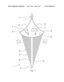
[0026] FIG. 1 schematically shows the invention, as viewed from above, wherein some of the elements are shown at different scales;
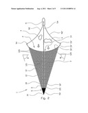
[0027] FIG. 2 shows the invention depicted in FIG. 1, wherein the device is further provided with a collection device;
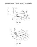
[0028] FIG. 3A-C shows a cut-through section of a guide element and the position of the guide element at different water flow velocities through the device; and
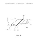
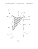
[0029] FIG. 4 shows the invention depicted when used to collect material in a river course.
DETAILED DESCRIPTION OF THE INVENTION
[0030] In the drawings, reference numeral 1 denotes a device according to the invention. The device is provided with several guide elements 12 and outer guide elements 18, 18' fixed to a form element 3. In the figures, the form element 3 is depicted as a net.
[0031] A front line 32, at the end portions 34, 34' thereof, is fixed to a door 94, 94'. The doors 94, 94' are connected to a vessel 9 with tow lines 92, 92'. The vessel 9 moves along a water surface 8 and in a direction denoted by a solid arrow. Upon movement of the vessel 9, the doors 94, 94', which are of a type known per se, will move out to the side of the vessel 9 when being pulled by the tow lines 92, 92'. The tow lines 92, 92' are comprised of a type known per se and may be comprised of ropes or metal wire. The doors 94, 94' will stretch out the front line 32 between themselves, whereby the front line 32 will assume a curved shape, as viewed from above and depicted in FIGS. 1 and 2. During towing, the end portions 34, 34' of the front line will define a front opening 2 of the device 1. By virtue of the vessel 9 towing the device 1 in the direction marked with a solid arrow, the water in the water surface 8 and a material 4 located on or directly below the water surface 8, will move in a direction relative to the device, as denoted with an open arrow in the figures.
[0032] The guide elements 12, 18, 18' are fixed to the net 3 in such a way that the longitudinal direction of the guide elements 12, 18, 18' is oblique relative to the pulling direction of the device 1. The guide elements 12, 18, 18', at the front ends 120 thereof, are fixed to the net 3 substantially at the front line 32. Collection ends 121 of the guide elements 12 end freely in a collection portion 14. The collection portion 14 extends from the front line 32 onto an end portion 16. The collection ends 121 of the outer guide elements 18, 18' may meet in the end portion 16 of the device 1. In an alternative embodiment, the collection ends 121 of the outer guide elements 18, 18' may be terminated somewhat apart from each other, whereby an opening 5 is formed between the collection ends 121, as shown in FIG. 2. In this opening, the device 1 may be provided with a collection unit 52 of a type known per se, for example a so-called skimmer or an oil trawl. The collection unit 52 may be provided with a fluid connection 54 of a type known per se, which is structured to bring collected material 4 to a collection craft, for example the vessel 9.
[0033] Material 4 located on or directly below the water surface 8, and between the doors 94, 94' in the front opening 2, will encounter one of the guide elements 12, 18, 18'. Due to the relative movement between the device 1 and the water, the material 4, or parts of the material 4, will be guided along the guide elements 12, 18, 18' in the direction of the collection portion 14. Some of the material 4 will move underneath the guide elements 12, 18, 18'. The material 4 moving underneath the outer guide elements 18, 18' will then be inaccessible for further concentration but may be further concentrated by repeating the sweep across the area using the device 1. The material 4 moving underneath one of the guide elements 12 will float up to the water surface 8 and then encounter the following guide element 12 and thereafter be guided towards the collection portion 14. From FIGS. 1 and 2, the skilled person will appreciate that this may be repeated several times. The material 4 will be further concentrated in the collection portion 14, which forms a channel between the front line 32 and the end portion 16 of the device. The material 4 being guided to the end portion 16 of the device will be significantly more concentrated than at the front opening 2 and suitable for collecting with equipment known per se, for example pumps or skimmers.
[0034] As shown in FIGS. 1 and 2, the device 1 is provided with several guide elements 12, which mainly have parallel longitudinal axes. The number of guide elements is determined by the desired perpendicular distance between the guide elements 12, by the width of the front opening 2, and by the angle α which is formed between the guide elements 12 and the front opening 2. In FIGS. 1 and 2, this angle is ca. 75°. This angle may be an angle in the region from of 70°, inclusive, to 80°, inclusive, but not limited to this angular region. It is up to the skilled person to determine which angle is optimum, insofar as the optimum angle may depend on which type of material 4 is desirable to concentrate further, for example oil or drifting seaweed. The optimum angle may also depend on the assumed wave height and assumed towing speed. As depicted in FIGS. 1 and 2, the angle is given as an internal angle measured from a base line extending between the doors 94, 94'. An angle of 0° will therefore correspond to a direction being parallel to the base line.
[0035] As shown in FIGS. 3A-C, the guide element 12 is comprised of a lengthy buoyancy body 122 of a type known per se, and which is provided with a skirt 124. The skirt 124 is cloth-shaped and surrounds a portion of the buoyancy body 122. The skirt is provided with a lengthy weight in the form of a weight rope 126 of a type known per se. The weight rope 126 may be fixed to the skirt 124 at the outside of the skirt 124. In an alternative embodiment, the skirt 124 may surround a portion of the weight rope 126. The skirt 124 is fixed to the net 3 with a lashing 128, as shown in FIGS. 3A-C. Alternatively, the skirt 124 may be fixed to the net 3 with a seam. In its position of use, when the device 1 is at rest relative to the water, the skirt 124 will be suspended down into the water from the buoyancy body 122 so as to allow the weight rope 126 to be located substantially below the buoyancy body 122, as shown in FIG. 3A. The net 3 will be submerged in the water and be kept floating by the guide elements 12. The distance from the net 3 to the water surface 8 is determined by the deep-draught of the skirt 124.
[0036] The FIGS. 3A-C show the mutual positions of the buoyancy body 122, the skirt 124 and the weight rope 126 at increasing towing speeds for the device 1. The movement of the water relative to the device 1 is shown with an open arrow. At a towing speed between 0 and 2 knots, as shown in FIG. 3A, the weight rope 126 will be located substantially below the buoyancy body 122. At a towing speed between 2 and 4 knots, as shown in FIG. 3B, the weight rope 126 will be located substantially sidelong the buoyancy body 122 and in a direction against the water flow. The net 3 will be lifted closer to the water surface 8. At a towing speed between 4 and 6 knots, as shown in FIG. 3C, the weight rope 126 will be located completely sidelong the buoyancy body 122 and in vicinity of the water surface 8 in a direction against the water flow. The net 3 will be lifted close to the water surface 8. The advantage thereof is that the towing resistance of the device 1 is reduced at higher towing speeds owing to the fact that the deep-draught of the skirt 124 is reduced. Insofar as the material 4 is allowed to pass beneath one or several guide elements 12 prior to being concentrated in the collection portion 14, the deep-draught of the skirt 124 may be reduced without expending too much of the collective capacity of the device 1 to concentrate the material 4 located on or directly below the water surface 8.
[0037] With respect other known solutions, the device 1 has a larger capacity for concentrating material 4 located on or directly below the water surface 8. For this purpose, it is advantageous that the front opening of the device 1 can be made very wide. It is known from gathering of seismic data to use doors 94, 94' forming a front opening from 1000 to 1400 meters. In principle, the front opening 2 of the device 1 may be made equally wide. The capacity also depends on the speed of the towing. Thus, it is advantageous that the deep-draught of the skirt 124 decreases at increasing towing speeds. Given that the structure of the device 1 is flexible and simultaneously is kept in position by the extended form element 3, the device 1 may also be used for larger wave heights than when using traditional booms.
[0038] The skilled person will appreciate that the device 1 may be stored and transported on board a vessel 9 in the same manner as that of the trawls and trawl bags used for fishing. Alternatively, the device 1 may be stored and transported on board a vessel 9 in the same manner as for equipment intended for carrying out seismic surveys offshore. Deployment and retrieval of the device 1 may therefore be carried out in a manner known per se.
[0039] In an alternative embodiment, as shown in FIG. 4, the device 1 may be comprised of substantially half of the device shown in FIG. 1. This implies that the net 3 is of a triangular shape with an associated guide elements 12 extending substantially in one longitudinal direction only. Then the collection portion 14 will comprise a side edge of the device 1, and the device 1 includes only one outer guide element 18. Such an embodiment may prove advantageous in context of concentrating material in a river 6. The front portion 2 may extend across a surface portion of the width of the river 6, possibly across the entire width of the river 6. With its end portions 34, 34', the front line 32 of the net is fixed at each river bank 62, 62'. The river water will flow past the device 1, and the device 1 will guide the material 4, which is located on or directly below the water surface, inward to the one river bank 62 where the material 4 may be collected in a manner known per se. This also has the advantage of the flow velocity being lower along the river bank 62 than in the midst of a river 6, which makes it easier to collect the material 4 along the river bank 62.
[0040] In an alternative embodiment (not shown), the guide elements 12, 18, 18' are comprised of narrow-spaced buoyant balls of a type known per se. In this embodiment, the buoyant balls may be attached both to the lower side and the upper side of the net 3, whereby the buoyant balls also comprise the skirt 124 of a guide element, and no weight rope 126 is used.
[0041] In a further alternative embodiment (not shown), the guide element 12 is comprised of a thick buoyant rope fixed to the net 3. The skilled person will also know that such a buoyant rope may comprise a part of the mesh thread of the net 3.
[0042] The foregoing description details certain preferred embodiments of the present invention and describes the best mode contemplated. It will be appreciated, however, that changes may be made in the details of construction and the configuration of components without departing from the spirit and scope of the disclosure. Therefore, the description provided herein is to be considered exemplary, rather than limiting, and the true scope of the invention is that defined by the following claims and the full range of equivalency to which each element thereof is entitled.
User Contributions:
Comment about this patent or add new information about this topic:
Images included with this patent application:
 |  |
 |  |
 |
| New patent applications in this class: | |
| Date | Title |
|---|---|
| 2016-07-07 | Marine lifting vessel |
| 2016-01-21 | Contraction and confinement of oil slicks on water, including water where ice is present, using non-ionic surfactants |
| 2016-01-21 | Floating barrier |
| 2015-12-31 | Stationary boom support system |
| 2015-05-07 | Floating lake system and methods of treating water within a floating lake |
| New patent applications from these inventors: | |
| Date | Title |
|---|---|
| 2013-12-26 | Device for collecting pollution on a water surface |
| 2013-06-13 | Device for collecting pollution on a water surface |
| Top Inventors for class "Hydraulic and earth engineering" | |
| Rank | Inventor's name |
|---|---|
| 1 | Joop Roodenburg |
| 2 | Thomas P. Taylor |
| 3 | Michael Tjader |
| 4 | Keith K. Millheim |
| 5 | John G. Oldsen |