Patent application title: ASYMMETRIC SEAL AND METHOD
Inventors:
Richard Xu (Tomball, TX, US)
Assignees:
BAKER HUGHES INCORPORATED
IPC8 Class: AE21B33128FI
USPC Class:
166387
Class name: Processes placing or shifting well part with sealing feature (e.g., packer)
Publication date: 2011-08-04
Patent application number: 20110186308
Abstract:
A seal including a contact area; and two arms extending in opposite
directions from the contact area, the seal when set exhibiting an
asymmetric cross section.Claims:
1. A seal comprising: a contact area; and two arms extending in opposite
directions from the contact area, the seal when set exhibiting an
asymmetric cross section.
2. A seal as claimed in claim 1 wherein the two arms are deflected radially by a differing number of degrees from one another.
3. A seal as claimed in claim 2 wherein the number of degrees of deflection of one arm ranges from about 45 to about 50 degrees from an axis of the seal.
4. A seal as claimed in claim 2 wherein the number of degrees of deflection of one arm ranges from about 40 to about 45 degrees from an axis of the seal.
5. A seal as claimed in claim 3 wherein the number of degrees of deflection of the other arm ranges from about 40 to about 45 degrees from an axis of the seal.
6. A seal as claimed in claim 1 wherein the two arms are of different length.
7. A seal as claimed in claim 6 wherein a shorter of the two arms ranges from about 90 percent of the length of the longer of the two arms to about 97 percent of the length of the longer of the two arms.
8. A seal as claimed in claim 1 wherein the seal further comprises a groove associated with each arm.
9. A seal as claimed in claim 8 wherein one of the grooves is of smaller axial dimension to limit radial deflection of one of the two arms.
10. A seal as claimed in claim 9 wherein the smaller groove is about 70 percent to about 80 percent of the axial dimension of a larger groove of the grooves.
11. A method for sealing an annulus comprising: running a seal as claimed in claim 1 to a target location; and setting the seal at the target location in a cross sectionally asymmetric configuration.
Description:
BACKGROUND
[0001] Annular seals for the drilling and completions industry have been known for many years and have benefitted over those years with improvements in material composition, setting strategies and systems, etc. Presently there are numerous types and kinds of seals available on the market. Notwithstanding ubiquitous solutions however, the number of possible situations is not finite and hence there is no end to the need and or desire for additional modifications to existing seal structure or design and indeed the development of entirely new concepts in sealing technology.
[0002] One type of annular seal uses a relatively thin wall portion of a tubular form that is intended to bulge outwardly upon axial compression and/or fluid pressure. Such seals employ a central area, sometimes including one or more pips, that is radially forced into contact with a casing. The portions of the seal sometimes referred to as arms, on either side of the central area create roughly symmetrical frustocones upon setting of the seal. Such seals can be constructed of metal, plastic, rubber, etc. and generally include an o-ring at a mandrel thereof to prevent fluid movement past the seal once it is set. Typically the O-ring is disposed at one end of the seal. O-rings are generally not placed at both ends of the seal as in the event that a liquid fluid filled the open space defined by the seal, it might well be impossible to set due to the relative incompressibility of liquid fluids. These seals have performed well for their intended purposes but do improvement as noted above is always desired. Accordingly the art will well receive seals having greater function.
SUMMARY
[0003] A seal including a contact area; and two arms extending in opposite directions from the contact area, the seal when set exhibiting an asymmetric cross section.
[0004] A method for sealing an annulus including running a seal as claimed in claim 1 to a target location; and setting the seal at the target location in a cross sectionally asymmetric configuration.
BRIEF DESCRIPTION OF THE DRAWINGS
[0005] Referring now to the drawings wherein like elements are numbered alike in the several Figures:
[0006] FIG. 1 is a schematic view of a prior art seal cross section in a set position;
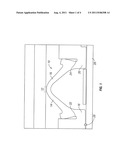
[0007] FIG. 2 is a schematic view of an embodiment of an asymmetric seal as disclosed herein that shows pressure acting on the seal from an end thereof that includes an o-ring seal;
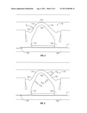
[0008] FIG. 3 is a schematic view of the same embodiment of an asymmetric seal as in FIG. 2 but showing pressure acting on the seal from an end thereof that does not include the o-ring seal;
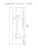
[0009] FIG. 4 is a schematic section view of another embodiment of an asymmetric seal as disclosed herein in a run in position;
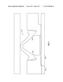
[0010] FIG. 5 is the embodiment of FIG. 4 in a set position.
DETAILED DESCRIPTION
[0011] Referring to FIG. 1, one of ordinary skill in the art will recognize a type of seal 10 known to the art. The seal 10 includes a contact area 12 that is positioned between two frustoconical (when in the set position as illustrated) arms 14 and 16 and two end rings 18 and 20. Each end ring also includes a groove, illustrated as 22 and 24 in FIG. 1 to promote radial movement of a central portion of the seal 10, i.e. the contact area 12 and the arms 14 and 16. Finally the seal 10 includes a mandrel seal such as an o-ring 26 positioned at one end of the seal 10. The O-ring seal 26 prevents pressure leakage between the seal 10 and a mandrel 28 but note that the o-ring 26 is positioned at only one end of the seal 10 to avoid potential hydraulic locking of the seal 10. This means to that pressure acting from one end of the seal is borne differently than from the other end of the seal. This is further discussed hereunder. With respect to FIG. 1, it is important to note in the illustration is that the two frustoconical arms 14 and 16 are generally symmetrical. The invention is distinct in this regard.
[0012] In accordance with the disclosure hereof, and referring to FIGS. 2 and 3, the inventor has discovered that an asymmetrical seal 110 performs better than the configuration of FIG. 1. The seal 110, it will be appreciated, has one arm 114 that is shorter than the other arm 116. The arm that is shorter should be the one that is on the same end of the seal 110 that the o-ring 126 is on. In this illustration, the one that is shorter is 114. It is important to have the shorter arm on the end with the o-ring 126 because of the way that pressure sources from one end of the seal 110 are borne versus pressures from the other end of the seal are borne. It is not relevant whether the pressure is from uphole, downhole, or any other direction indicator but rather only whether the pressure from a particular end of the seal will have access to an inside surface 130 of the seal 110 or not. Pressure that comes from an end of the seal 110 that does not have the o-ring will have access to the inside surface of the seal whereas pressure from an end of the seal 110 that does have the o-ring 126 will not have access to the inside surface 130 of the seal.
[0013] As can be seen in FIGS. 2 and 3, the result of the longer arm 116 upon setting is that it achieves a shallower angle relative to the mandrel 128 or axis of the seal 110 than the angle achieved by the shorter arm 114. Angle ranges for the arms 114 and 116 is about 45 degrees to about 50 degrees and about 40 degrees to about 45 degrees, respectively relative to a longitudinal axis of the seal 110. Such a configuration has been shown via Finite Element Analysis to improve pressure rating for the seal 110 over similar symmetrical seals 10. It is believed that the shorter arm 114 at a higher angle has greater rigidity against the pressure on an outside surface 132 of the seal, see arrow Po, which stands for pressure o-ring end. This is helpful since pressure from that end of the seal, due to the location of o-ring 126, is borne only at surface 132 and the seal 110 is not assisted from the inside surface 130. The longer arm 116, although it is necessarily less rigid due to length, benefits from the pressure from its end of the seal on surface 130 thereby reducing the ultimate load on the seal from the outside surface 134, see arrows Pno, which stands for pressure non o-ring end. In other words, because the pressure affects both inside 130 and outside 134 of the seal 110 from this direction, the pressure differential directly across the arm 116 is insignificant and therefore the reduced rigidity of the longer arm 116 is of no consequence. The length of the shorter arm 114 relative to the longer arm 116 is in one embodiment in the range of about 90% to about 97% of the length of the longer arm 116.
[0014] Referring to FIGS. 4 and 5, an alternate embodiment asymmetrical seal 210 is illustrated. The ultimate set position of this embodiment is similar to the foregoing described embodiment in that one arm achieves an angle relative to the mandrel 228 or longitudinal axis of the seal 210 that is greater than an angle achieved by the other arm but it does not require that the length of the arms differ. Rather, in this embodiment it is grooves 222 and 224 that are distinct. Configuring a groove 222 or 224, (depending upon which groove is proximate the o-ring 226, which is groove 222 in the illustration) with a limited amount of space used for accommodation of the arm associated therewith. Stated alternatively, the amount of space available within a groove can be a limiting factor in how much radial movement the arm can experience. By carefully sizing the grooves 222 and 224, one can ensure that one arm will deflect radially outwardly less than the other arm thereby ensuring that the arm that is allowed to deflect farther will achieve a greater angle relative to the mandrel 228 or an axis of the seal 210 resulting in an asymmetric seal cross section. This configuration has been noted above to exhibit improved results over the seal 10 of FIG. 1. The Seal configuration of FIG. 3 thus is also beneficial to the art. The groove size limitation that is contemplated is that the smaller groove is in a range of from about 70% to about 80% of the size of the larger groove, the larger groove being the one that is proximate the O-ring 226.
[0015] While each of the configurations discussed above are capable of achieving the favorable results of better pressure ratings over the seal 10 of FIG. 1, this is not to say that the two configurations cannot be combined. To the contrary, the above-disclosed concepts can indeed be combined if desired.
[0016] While one or more embodiments have been shown and described, modifications and substitutions may be made thereto without departing from the spirit and scope of the invention. Accordingly, it is to be understood that the present invention has been described by way of illustrations and not limitation.
User Contributions:
Comment about this patent or add new information about this topic:
Images included with this patent application:
 |  |
 |  |
| Similar patent applications: | |
| Date | Title |
|---|---|
| 2008-12-18 | Elastomeric element installation tool and method |
| 2010-05-06 | Calorimetric distributed temperature system and methods |
| 2009-02-19 | Buoyancy tensioning systems for offshore marine risers and methods of use |
| 2011-02-10 | Tubular system with selectively engagable sleeves and method |
| 2011-08-04 | Outside casing conveyed low flow impedance sensor gauge system and method |
| New patent applications in this class: | |
| Date | Title |
|---|---|
| 2022-05-05 | Controlled deformation and shape recovery of packing elements |
| 2022-05-05 | Packers |
| 2019-05-16 | Flow-through wellbore isolation device |
| 2019-05-16 | Wellbore isolation devices with degradable non-metallic components |
| 2018-01-25 | Wellbore isolation devices and methods of use |
| New patent applications from these inventors: | |
| Date | Title |
|---|---|
| 2012-10-04 | Method for isolating and completing multi-zone gravel packs |
| 2011-08-04 | Collet system |
| 2010-11-25 | Flow-actuated actuator and method |
| Top Inventors for class "Wells" | |
| Rank | Inventor's name |
|---|---|
| 1 | Michael L. Fripp |
| 2 | Jean Marc Lopez |
| 3 | Michael H. Johnson |
| 4 | Jørgen Hallundbaek |
| 5 | Dennis P. Nguyen |