Patent application title: COMPOSITE BAR FOR THE CHASSIS OF A VEHICLE
Inventors:
Fabrizio Favaretto (Formigine, IT)
Assignees:
FERRARI S.p.A.
IPC8 Class: AB62D2100FI
USPC Class:
280781
Class name: Wheeled running gear specific vehicle frame
Publication date: 2011-07-21
Patent application number: 20110175337
Abstract:
A composite bar for the chassis of a vehicle; the composite bar consists
of at least two extruded elements which are internally hollow and are
butt jointed at a junction area; each extruded element has a trapezoidal
cross section having a major base, a minor base parallel and opposite to
the major base, and two side walls; a first end of a first extruded
element arranged in the junction area has no major base; and a second end
of a second extruded element arranged in the junction area is
interference fitted into the first end through the missing major base.Claims:
1. A composite bar for a chassis of a vehicle, the composite bar
comprising at least first and second extruded elements which are hollow
inside and which are butt jointed together at a junction area, with each
of the first and second extruded elements comprising a trapezoidal cross
section comprising a major base, a minor base parallel and opposite to
the major base, and two side walls, with a first end of a first extruded
element arranged in the junction area defining a major base opening;
wherein the first and second extruded elements have a same trapezoidal
cross section, which is constant along a whole extension of each extruded
element; and wherein a second end of a second extruded element is
arranged in a junction area interference fitted, along a direction
perpendicular to the bases of the first and second extruded elements,
inside the first end through the major base opening, with an outer
surface of each side wall of the second extruded element in contact with
a first inner surface of a corresponding side wall of the first extruded
element.
2. A composite bar according to claim 1, wherein the second end of the second extruded element comprises an appendix that forms an extension of the major base and rests on the major base of the first extruded element.
3. A composite bar according to claim 1 and comprising fastening members that are arranged in the junction area and block the first and second extruded elements against each other, wherein the fastening members interact with the bases, of the first and second extruded elements to push at least one base of the first extruded element towards a corresponding base of the second extruded element.
4. A composite bar according to claim 3, wherein action generated by the fastening members is applied along a direction perpendicular to the bases of the first and second extruded elements.
5. A composite bar according to claim 1 and comprising fastening members that are arranged in the junction area and block the first and second extruded elements against each other, wherein for each fastening member, the first through hole or the second through hole is covered with a threaded bushing which is fixed either to the first extruded element or to the second extruded element, respectively.
6. A composite bar according to claim 1 and comprising fastening members that are arranged in the junction area and block the first and second extruded elements against each other, wherein the fastening members are arranged through the bases, of the first and second extruded elements and are adapted to pull together the extruded elements themselves.
7. A composite bar according to claim 6, wherein at least one fastening member is arranged through the minor bases of the first and second extruded elements.
8. A composite bar according to claim 6, wherein the second end of the second extruded element comprises an appendix that forms an extension of the major base and rests on the major base of the first extruded element and at least one fastening member is arranged through the wall of the major base of the first extruded element and through the appendix of the second extruded element.
9. A composite bar according to claim 1 and comprising a second central extruded element and two first lateral extruded elements arranged on opposite sides of the central extruded element and butt jointed to the second extruded element at two distinct junction areas.
10. A vehicle, comprising: a chassis comprising a composite bar, the composite bar comprising: a first extruded element that is hollow, comprising a first trapezoidal cross section constant along its length and comprising a first major base, a first minor base parallel and opposite the first major base, and two first side walls, the first extruded element at a first end defining a major base opening opposite the first minor base; and a second extruded element that is hollow, comprising a second trapezoidal cross section constant along its length and comprising a second major base, a second minor base parallel and opposite the second major base, and two second side walls, wherein the second extruded element is butt jointed to the first extruded element at a junction area, with a second end of the second extruded element being interference fit, in a direction perpendicular to the bases, inside the first end, through the major base opening of the first extruded element, with the second trapezoidal cross section substantially coextensive with the first trapezoidal cross section, and with an outer surface of each second side wall of the second extruded element arranged in contact with a first inner surface of a corresponding first side wall of the first extruded element.
11. A composite bar according to claim 10, wherein the second end of the second extruded element comprises an appendix that forms an extension of the major base and rests on the major base of the first extruded element.
12. A composite bar according to claim 10 and comprising fastening members that are arranged in the junction area and block the first and second extruded elements against each other.
13. A composite bar according to claim 12, wherein the fastening members are adapted to interact with the bases of the first and second extruded elements to push at least one base of the first extruded element towards a corresponding base of the second extruded element.
14. A composite bar according to claim 13, wherein the fastening members are adapted to push along a direction perpendicular to the bases of the first and second extruded elements.
15. A composite bar according to claim 12, wherein each fastening member comprises a screw, which is inserted through a first through hole obtained through the first extruded element, and a second through hole obtained through the second extruded element.
16. A composite bar according to claim 15, wherein for each fastening member, the first through hole or the second through hole is covered with a threaded bushing which is fixed either to the first extruded element or to the second extruded element.
17. A composite bar according to claim 12, wherein the fastening members are arranged through the bases, of the first and second extruded elements and are adapted to pull together the extruded elements.
18. A composite bar according to claim 17, wherein at least one fastening member is arranged through the minor bases of the first and second extruded elements.
19. A composite bar according to claim 17, wherein the second end of the second extruded element comprises an appendix that forms an extension of the major base and rests on the major base of the first extruded element and at least one fastening member is arranged through the wall of the major base of the first extruded element and through the appendix of the second extruded element.
20. A composite bar according to claim 12 and comprising a second central extruded element and two first lateral extruded elements arranged on opposite sides of the central extruded element and butt jointed to the second extruded element at two distinct junction areas.
Description:
PRIORITY CLAIM
[0001] This application claims the benefit of priority under 35 U.S.C. Section 119 to Italian Patent Application Serial No. B02010A 000024, filed on Jan. 18, 2010, which is incorporated herein by reference in its entirety.
TECHNICAL FIELD
[0002] The present subject matter relates to a composite bar for the chassis of a vehicle, and more particularly to a car chassis made by joining a plurality of extruded elements, to which explicit reference will be made in the following description without loss of generality.
BACKGROUND
[0003] As described in patent application WO2005061311A1, for example, a car chassis made by joining a plurality of extruded element comprises a plurality of linear bars, which have a constant section, are made by extrusion, and are joined to one another by welding at structural nodes defined by junction bodies provided with pockets for accommodating the head of the linear bars.
[0004] Some linear bars may not be monolithic but must imperatively be composite (i.e. made of several parts) and removable (i.e. the parts are connectable and disconnectable from one another) to allow some particularly large parts of the car (typically, but not only, the thermal engine and the gearbox) to be assembled and disassembled. A composite bar is made by joining several extruded elements which are butt jointed to one another. Currently, the butt jointing of the two extruded elements includes using junction bodies which rest on the two extruded elements and are fixed (typically by means of screws) to both extruded elements; several junction bodies with flat cross section or junction bodies with a with an either "L"-shaped or "U"-shaped cross section are required to confer an adequate stiffness to the butt joint. However, using the junction bodies implies both an increase of the overall weight of the chassis (the weight of the junction bodies is "wasted" because the only function of the junction bodies is to make some parts removable) and an increase of dimensions (the junction bodies locally increase the size of the linear bar).
[0005] DE3811427A1 and EP0631924A1 describe a composite bar for the chassis of a vehicle which consists of two extruded elements which are butt jointed together at a junction area. Each extruded element has a trapezoidal cross section having a major base, a minor base parallel and opposite to the major base and two side walls; furthermore, one end of an extruded element arranged in the junction area has no major base. In the composite bar described in DE3811427A1 and EP0631924A1, the end of an extruded element has a deformation so that the cross section of the end of the extruded element may be axially inserted without interference into one end of the other extruded element. However, the need to locally deform the end of an extruded elements implies a further mechanical machining which complicates the machining of the extruded elements and may locally reduce the mechanical strength at the deformation itself.
SUMMARY
[0006] Some examples provide a composite bar for the chassis of a vehicle, which composite bar is free from the drawbacks described above and, in particular, is easy and cost-effective to be manufactured.
[0007] Examples of a composite bar for the chassis of a vehicle are provided as claimed in the attached claims.
BRIEF DESCRIPTION OF THE DRAWINGS
[0008] The present invention will now be described with reference to the accompanying drawings, which illustrate a non-limitative embodiment thereof, in which:
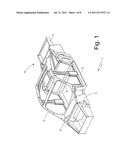
[0009] FIG. 1 is a diagrammatic, perspective view of a chassis of a vehicle provided with a composite bar made in accordance with some examples;
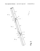
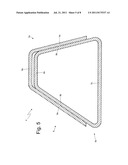
[0010] FIG. 2 is a perspective view of the composite bar which consists of several extruded elements butt jointed together;
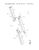
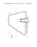
[0011] FIG. 3 is an exploded, perspective view of the composite bar in FIG. 2;
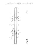
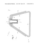
[0012] FIG. 4 is a longitudinal section of the composite bar in FIG. 2;
[0013] FIG. 5 is a cross section view taken along line V-V of the composite bar in FIG. 2;
[0014] FIG. 6 is a cross section view taken along line VI-VI of the composite bar in FIG. 2;
[0015] FIG. 7 is a cross section view taken along line VII-VII of the composite bar in FIG. 2; and
[0016] FIG. 8 is a cross section view taken along line VIII-VIII of the composite bar in FIG. 2.
DETAILED DESCRIPTION
[0017] In FIG. 1, numeral 1 indicates as a whole a chassis of a car, which comprises a number of linear bars 2, which have a constant section, are made by extrusion, and are joined together by welding at structural nodes defined by junction bodies 3 (further details on the shape of the junction bodies 3 are described in patent application WO2005b061311A1, which is incorporated herein by reference in its entirety).
[0018] A linear bar 4 is composite and removable (i.e. may be split into several parts which are connectable and disconnectable) to allow some particularly large parts of the car (typically, but not only, the thermal engine and the gearbox which are centrally arranged in chassis 1) to be assembled and disassembled.
[0019] As shown in FIGS. 2 and 3, composite bar 4 consists of two lateral extruded elements 5a and of a central extruded element 5b, which is arranged between the two lateral extruded elements 5a and is butt jointed to the two lateral extruded elements 5a at two distinct junction areas 6.
[0020] As shown in FIGS. 5 and 7, each extruded element is internally hollow and has a trapezoidal cross section having a major base 7, a minor base 8 parallel and opposite to the major base 7, and two side walls 9. It is worth noting that the extruded elements 5 have exactly the same cross section, i.e. their cross sections have exactly the same shape and the same size; the extruded elements 5 thus have the same mechanical performances and are produced in the same extrusion template (die) (the differences between the extruded elements 5 are made upon the extrusion through mechanical removal machining).
[0021] As shown in FIGS. 3, 4, 5 and 7, one end of each extruded element 5a arranged in the corresponding junction area 6 has no major base 7a; thereby, a corresponding end of the extruded element 5b arranged in the junction area 6 is interference fitted according to a direction perpendicular to the bases 7 and 8 of the two extruded elements 5 into the end of the extruded element 5a through the missing major base 7a. Therefore, at each junction area 6, the minor base 8a of the corresponding extruded element 5a is arranged parallel to and facing the minor base 8b of the extruded element 5a, and the side walls 9a of the extruded element 5a are arranged parallel to and facing the corresponding side walls 9b of the extruded element 5b. In other words, at each junction area 6, one end of the extruded element 5b is interference fitted into one end of the extruded element 5a through the missing major base 7, so that an outer surface of each side wall 9b of the extruded element 5b is arranged in contact with an inner surface of a corresponding side wall 9a of the extruded element 5a.
[0022] As previously mentioned, the extruded elements 5 have exactly the same cross section and therefore, at each junction area 6, the minor base 8a of the corresponding extruded element 5a is never able to come in contact with the minor base 8b of the extruded element 5b due to an apparent mechanical interference which limits the approach between the two minor bases 8. Therefore, at each junction area 6, a mechanical interference fitting of the extruded element 5b into the extruded element 5a is obtained; as previously mentioned, at each junction area 6, the insertion of the extruded element 5b into the extruded element 5a is possible because the extruded element 5a has no major base 7a at the junction area 6.
[0023] It is worth noting that the two extruded elements 5 have exactly the same trapezoidal cross section, which is strictly constant along the whole extension of each extruded element 5, even at the junction area 6; i.e. the trapezoidal cross section of both extruded elements 5 is not subject to any variation even in the junction area 6.
[0024] According to an embodiment shown in FIGS. 2, 3, 4, 6 and 8, each end of the extruded element 5b comprises an appendix 10, which forms a seamless extension of the major base 7b and rests on the major base 7a of the corresponding extruded element 5a.
[0025] Fastening members 11 which block the two extruded elements 5 against each other are provided in each junction area 6. In the embodiments shown in the accompanying figures, the fastening members 11 are removable, i.e. do not define a permanent connection but may be removed (to allow the separation of the extruded elements 5) and then restored (to allow the re-composition of the composite bar 4). According to a different embodiment, the fastening members 11 are permanent (e.g. rivets or welding) when the removability of the composite bar 4 is not required.
[0026] The fastening members 11 interact only with the bases 7 and 8 of the two extruded elements 5 to push each base 7 and 8 of the extruded element 5a towards the corresponding base 7 and 8 of the extruded element 5b. In other words, the action generated by the fastening members 11 is applied only along a direction perpendicular to the bases 7 and 8 of the two extruded elements 5.
[0027] As shown in FIGS. 7 and 8, each fastening member 11 consists of a screw 12 which is inserted through a through hole 13 obtained through the extruded element 5a and through a through hole 14 obtained through the extruded element 5b. In each fastening member 11, either the hole 13 obtained through the extruded element 5a or the hole 14 obtained thorough the extruded element 5b is covered with a threaded bushing 15, which is fixed (typically welded) to the extruded element 5 and centrally has a threaded hole, which is engaged by screw 12. The function of the threaded bushings 15 is to increase the fastening ability of the fastening members 11 because the thickness of the extruded elements 5 is relatively small and thus does not allow to obtain a threading of adequate axial size.
[0028] As shown in FIG. 4, the fastening members 11 are arranged only through the bases 7 and 8 of the extruded elements 5 and, at each junction area 6, serve the function of pulling together the corresponding extruded elements 5. In particular, the fastening members 11 are arranged through the minor bases 8 of the extruded elements 5 and are arranged through the major bases 7a of the extruded elements 5a and through the appendixes 10 of the extruded element 5b which form an extension of the major base 7b of the extruded element 5b.
[0029] According to a different embodiment (not shown), the appendixes 10 of major base 7b of the extruded element 5b are not present (and therefore the fastening members 11 which concern the appendixes 10 are not present).
[0030] At each junction area 6, a contact occurs between the minor base 8a of the extruded element 5a and the minor base 8b of the extruded element 5b (as shown in FIGS. 5 and 7), a contact occurs between the major base 7a of the extruded element 5a and the major base 7b of the extruded element 5b, which major base 7b is extended by appendix 10 (as shown in FIGS. 6 and 8), and a contact occurs between the side walls 9a of the extruded element 5a and the side walls 9b of the extruded element 5b (as shown in FIGS. 5 and 7). It is worth specifying that, in each junction area 6, the bases 7 and 8 of the two extruded elements 5 transmit stresses to each other due to the presence of fastening members 11, while the side walls 9 of the two extruded elements 5 transmit stresses to each other by means of the mechanical interference fitting which exists between the side walls 9 themselves. Due to the presence of four distinct contact areas in each junction area 6, the butt joint between two extruded elements 5 is particularly tough and strong and substantially has the same mechanical strength as a similar monolithic bar (i.e. without junctions).
[0031] The above-described composite bar 4 has many advantages, as it has a high mechanical strength (substantially equal to a similar monolithic bar) while having very small additional parts for the junctions (e.g. appendixes 10 of the major base 7b of the extruded element 5b), thus of minimum weight and size.
User Contributions:
Comment about this patent or add new information about this topic:
Images included with this patent application:
 |  |
 |  |
 |  |
 |  |
| Similar patent applications: | |
| Date | Title |
|---|---|
| 2009-05-28 | Console system suitable for use in an interior cabin of a vehicle |
| 2009-07-23 | Information based controlling of chassis height of a vehicle |
| 2011-09-01 | Stabilizing strut for a chassis of a vehicle |
| 2010-08-19 | Diverter for the seatbelt system of a motor vehicle |
| 2011-05-26 | Tie rod for wheel suspension of a vehicle |
| New patent applications in this class: | |
| Date | Title |
|---|---|
| 2019-05-16 | Dual-sided transparent display assemblies with non-transparent circuits |
| 2016-04-21 | Vehicle body with a reinforcing component of the nodes and the hinge of the tailgate frame |
| 2016-03-03 | Arcuate frame for a vehicle |
| 2015-12-24 | Vehicle |
| 2015-12-10 | Support structure and method of producing a support structure |
| Top Inventors for class "Land vehicles" | |
| Rank | Inventor's name |
|---|---|
| 1 | Osamu Fukawatase |
| 2 | Christopher P. D'Aluisio |
| 3 | Richard W. Mccoy |
| 4 | Jun Yeol Choi |
| 5 | Yusuke Fujiwara |